KS3017 Keyestudio Raspberry Pico IO Shield
Jump to navigation
Jump to search
Description
The Raspberry Pico IO shield is designed for the Raspberry Pi Pico development board, without soldering. It also incorporates communications ports like 2 x I2C, 2 x UART, 2 x SPI, 3 x analog IO and 13 x digital IO as well as a 6.5-12V power interface. The integrated Lego position holes can assist to wire up multiple sensors or modules, which exceedingly increase more functions
Parameters
- Power supply: 5V
- Output current: ≦500mA
- DC input voltage: 6.5-12V
- Output voltage: DC3.3V\5V
- Recommended ambient temperature: -10°C ~ 50°C
- Size:45.339MM *83.617MM
- Spacing of pin headers: 2.54mm
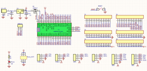
Schematic Diagram
Pins
- Digital IO x 13:GP2, GP3, GP12 ~ GP22
- Analog IO x 3: GP26, GP27, GP28
- UART x 2: UART0, UART1
- I2C x 2: I2C0, I2C1
- SPI x 2: SPI0, SPI1
- Power interface: 6.5 - 12V
- GPIO pins, are used for the RP2040 chip of the Pico development board, as shown below;
- GPIO29: for ADC mode(ADC3) measure VSYS/3
- GPIO25: connected to LEDs of users
- GPIO24: VBUS sensing-if VBUS exists, it is the high level, in contrast, it is the ow level
- GPIO23: on-board SMPS chip control pin
- In addition to 26 GPIO pins(GP0~GP22, GP26_A0, GP27_A1, GP28_A2) and 7 GND pins, the Pico board has 7 physic pins as follows
- PIN40: VBUS(5V)
- PIN39: VSYS(2~5V)
- PIN37: 3V3_EN(on-board SMPS chip Enable)
- PIN36: 3V3(3.3V)
- PIN35: ADC_VREF(ADC)
- PIN33: AGND(analog)
- PIN30: RUN(boot/forbid Pico)
