Getting Started with Mixly: Difference between revisions
Keyestudio (talk | contribs) No edit summary |
Keyestudio (talk | contribs) No edit summary |
||
| Line 49: | Line 49: | ||
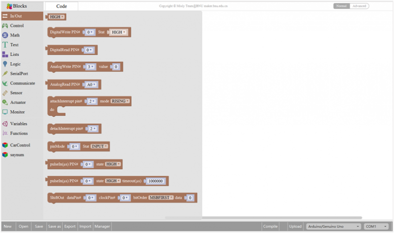
===In/Out Block=== | ===In/Out Block=== | ||
<br>[[Image:3.1-1.png|800px|frameless]]<br> | <br>[[Image:3.2-1.png|800px|frameless]]<br> | ||
{| width="80%" cellspacing="0" border="1" | |||
|- | |||
! align="center" scope="col" | No. | |||
! align="center" scope="col" | BLOCK ICON | |||
! align="center" scope="col" | DEFINITION | |||
|- | |||
| align="center" | 1 | |||
| align="center" | <br>[[Image:3.2-2.png|800px|frameless]]<br> | |||
| align="center" | Returns HIGH or LOW voltage | |||
|- | |||
| align="center" | 2 | |||
| align="center" | <br>[[Image:3.2-3.png|800px|frameless]]<br> | |||
| align="center" | Write digital value to a specific Port. | |||
Digital Output: set the HIGH or LOW output for IO pins | |||
|- | |||
| align="center" | 3 | |||
| align="center" | <br>[[Image:3.2-4.png|800px|frameless]]<br> | |||
| align="center" | Returns a digital value of a specific Port. | |||
Digital IO Read Pin, generally used to read the HIGH or LOW level detected by Digital sensor | |||
|- | |||
| align="center" | 4 | |||
| align="center" | <br>[[Image:3.2-5.png|800px|frameless]]<br> | |||
| align="center" | Write analog value between 2 and 255 to a specific Port. | |||
Analog Output: set the Analog value output by Analog IO pins (0~255). | |||
|- | |||
| align="center" | 5 | |||
| align="center" | <br>[[Image:3.2-6.png|800px|frameless]]<br> | |||
| align="center" | Returns value between 0 and 1023 of a specific Port. | |||
Analog IO Read Pin, generally used to read the Analog value detected by Analog sensor. | |||
|- | |||
| align="center" | 6 | |||
| align="center" | <br>[[Image:3.2-7.png|800px|frameless]]<br> | |||
| align="center" | External Interrupts function, with three trigger interrupt modes RISING, FALLING, CHANGE. | |||
|- | |||
| align="center" | 7 | |||
| align="center" | <br>[[Image:3.2-8.png|800px|frameless]]<br> | |||
| align="center" | Detachs interrupt to a specific Port. | |||
Turn off the given interrupt function. | |||
|- | |||
| align="center" | 8 | |||
| align="center" | <br>[[Image:3.2-9.png|800px|frameless]]<br> | |||
| align="center" | Set the IO pins as Output or Input state | |||
|- | |||
| align="center" | 9 | |||
| align="center" | <br>[[Image:3.2-10.png|800px|frameless]]<br> | |||
| align="center" | Read the continuous time of HIGH or LOW pulse from IO pins | |||
( generally used for ultrasonic ranging) | |||
|- | |||
| align="center" | 10 | |||
| align="center" | <br>[[Image:3.2-11.png|800px|frameless]]<br> | |||
| align="center" | Read a pulse (either HIGH or LOW) on a pin within a time set in timeout. | |||
|- | |||
| align="center" | 11 | |||
| align="center" | <br>[[Image:3.2-12.png|800px|frameless]]<br> | |||
| align="center" | Set the ShiftOut data pin, clock pin. Output the data needed from the bitOrder MSBFIRST or LSBFIRST (Most Significant Bit First, or, Least Significant Bit First). | |||
Generally used for controlling the 74HC595 CHIP. | |||
|- | |||
| align="center" | 12 | |||
| align="center" | <br>[[Image:3.2-13.png|800px|frameless]]<br> | |||
| align="center" | This is the function interface under Normal mode. If select Advanced mode, the functions will be more. | |||
|- | |||
|} | |||
'''For example''' | |||
Connect your Arduino Uno board, then follow the steps below to light the Pin13 led on Arduino UNO. | |||
<br>[[Image:3.2 led D13.png|800px|frameless]]<br> | |||
===Control Block=== | |||
<br>[[Image:3.3.png|800px|frameless]]<br> | |||
{| width="80%" cellspacing="0" border="1" | |||
|- | |||
! align="center" scope="col" | No. | |||
! align="center" scope="col" | BLOCK ICON | |||
! align="center" scope="col" | DEFINITION | |||
|- | |||
| align="center" | 1 | |||
| align="center" | <br>[[Image:3.3-1.png|800px|frameless]]<br> | |||
| align="center" | Initialization (run only once) | |||
|- | |||
| align="center" | 2 | |||
| align="center" | <br>[[Image:3.3-2.png|800px|frameless]]<br> | |||
| align="center" | End the program, means the program will stop running when use this block. | |||
|- | |||
| align="center" | 3 | |||
| align="center" | <br>[[Image:3.3-3.png|800px|frameless]]<br> | |||
| align="center" | Delay function, click to select '''ms''' or '''us''' | |||
(pause the program for the amount of time (in milliseconds) specified as parameter. There are 1000 milliseconds in a second.) | |||
|- | |||
| align="center" | 4 | |||
| align="center" | <br>[[Image:3.3-4.png|800px|frameless]]<br> | |||
| align="center" | '''if_do''' function (first evaluate a value be true or false, if a value is true, then do some statement. | |||
You can click the blue gear icon to select the '''else if''' block or '''else''' block.) | |||
|- | |||
| align="center" | 5 | |||
| align="center" | <br>[[Image:3.3-5.png|800px|frameless]]<br> | |||
| align="center" | '''switch''' function. You can click the blue gear icon to select the '''case''' block or '''default''' block. (used to evaluate several programs then execute the corresponding function matched with program.) | |||
|- | |||
| align="center" | 6 | |||
| align="center" | <br>[[Image:3.3-6.png|800px|frameless]]<br> | |||
| align="center" | Equal to [https://www.arduino.cc/reference/en/language/structure/control-structure/for/ '''for''' statement]. | |||
|- | |||
| align="center" | 7 | |||
| align="center" | <br>[[Image:3.3-7.png|800px|frameless]]<br> | |||
| align="center" | A '''while''' loop statement. | |||
|- | |||
| align="center" | 8 | |||
| align="center" | <br>[[Image:3.3-8.png|800px|frameless]]<br> | |||
| align="center" | '''break''' function, used to exit from the containing loop. | |||
|- | |||
| align="center" | 9 | |||
| align="center" | <br>[[Image:3.3-9.png|800px|frameless]]<br> | |||
| align="center" | '''millis()''' function, returns the system running time since the program started. | |||
(The unit can be '''ms''' (milliseconds) or '''μs'''(microsecond)). | |||
|- | |||
| align="center" | 10 | |||
| align="center" | <br>[[Image:3.3-10png|800px|frameless]]<br> | |||
| align="center" | Timer interrupt function, that is, set a trigger interrupt for the amount of time (in milliseconds) specified as parameter. | |||
|- | |||
| align="center" | 11 | |||
| align="center" | <br>[[Image:3.3-11.png|800px|frameless]]<br> | |||
| align="center" | Timer interrupt start block | |||
|- | |||
| align="center" | 12 | |||
| align="center" | <br>[[Image:3.3-12.png|800px|frameless]]<br> | |||
| align="center" | Timer interrupt stop block | |||
|- | |||
|} | |||
'''For example''' | |||
Compile and upload the program below to your Arduino board, you should see Pin13 LED on Arduino UNO continue to flash.(with an interval of 1s, equal to 1000ms) | |||
<br>[[Image:3.3 flash.png|800px|frameless]]<br> | |||
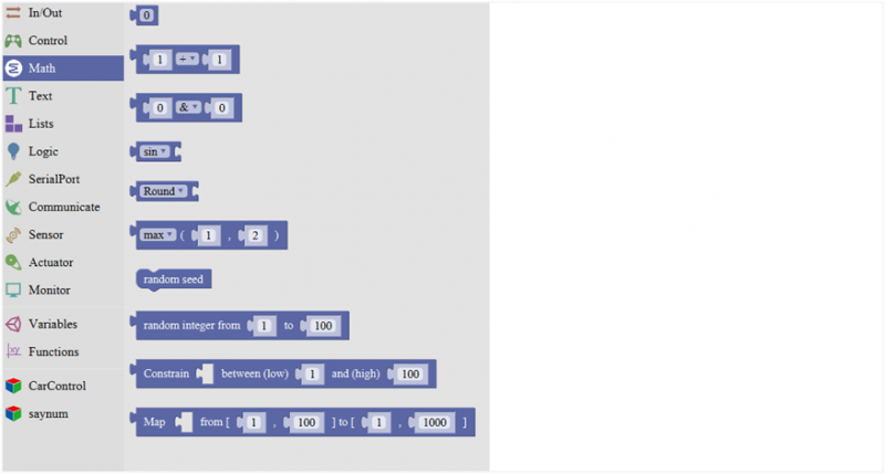
=== Math Block=== | |||
<br>[[Image:3.4.png|800px|frameless]]<br> | |||
{| width="80%" cellspacing="0" border="1" | |||
|- | |||
! align="center" scope="col" | No. | |||
! align="center" scope="col" | BLOCK ICON | |||
! align="center" scope="col" | DEFINITION | |||
|- | |||
| align="center" | 1 | |||
| align="center" | <br>[[Image:3.4-1.png|800px|frameless]]<br> | |||
| align="center" | A number | |||
|- | |||
| align="center" | 2 | |||
| align="center" | <br>[[Image:3.3-2.png|800px|frameless]]<br> | |||
| align="center" | Click to select the Arithmetic Operators: | |||
[https://www.arduino.cc/reference/en/language/structure/arithmetic-operators/subtraction/ '''+(addition); -(subtraction)''']; | |||
[https://www.arduino.cc/reference/en/language/structure/arithmetic-operators/multiplication/ '''x (Multiplication); ÷ (division)''']; | |||
[https://www.arduino.cc/reference/en/language/structure/bitwise-operators/bitwisexor/ '''% (remainder); ^ (bitwise xor)'''] | |||
|- | |||
| align="center" | 3 | |||
| align="center" | <br>[[Image:3.3-3.png|800px|frameless]]<br> | |||
| align="center" | Click to select the [https://www.arduino.cc/reference/en/language/structure/bitwise-operators/bitwiseand/ '''& (bitwise end)''']; [https://www.arduino.cc/reference/en/language/structure/bitwise-operators/bitwiseor/ '''l (bitwise or)''']; [https://www.arduino.cc/reference/en/language/structure/bitwise-operators/bitshiftleft/ '''<< (bitshift left)''']; [https://www.arduino.cc/reference/en/language/structure/bitwise-operators/bitshiftright/ '''>> (bitshift right)'''] | |||
|- | |||
| align="center" | 4 | |||
| align="center" | <br>[[Image:3.3-4.png|800px|frameless]]<br> | |||
| align="center" | Click to select the [https://www.arduino.cc/reference/en/language/functions/trigonometry/sin/ '''sin''']; [https://www.arduino.cc/reference/en/language/functions/trigonometry/cos/ '''cos''']; '''tan; asin; acos; atan; ln; log10; e^; 10^;''' [https://www.arduino.cc/reference/en/language/structure/compound-operators/increment/ '''++ (increment)'''] ; | |||
[https://www.arduino.cc/reference/en/language/structure/compound-operators/decrement/ '''-- (decrement)'''] | |||
|- | |||
| align="center" | 5 | |||
| align="center" | <br>[[Image:3.3-5.png|800px|frameless]]<br> | |||
| align="center" | Click to select the '''Round; Ceil; Floor; abs; sq; sqrt''' | |||
'''Round:''' Returns the integer part a number using around. | |||
'''Ceil:''' Returns the integer part a number using ceil. | |||
'''Floor:''' Returns the integer part a number using floor. | |||
'''abs:''' Return the absolute value of a number. | |||
'''sq:''' Return the square of a number. | |||
'''sqrt:''' Return the square root of a number. | |||
|- | |||
| align="center" | 6 | |||
| align="center" | <br>[[Image:3.3-6.png|800px|frameless]]<br> | |||
| align="center" | If select the '''max''', returns the larger number; | |||
if select the '''min''', returns the smaller number. | |||
|- | |||
| align="center" | 7 | |||
| align="center" | <br>[[Image:3.3-7.png|800px|frameless]]<br> | |||
| align="center" | Initialize the random seed | |||
|- | |||
| align="center" | 8 | |||
| align="center" | <br>[[Image:3.3-8.png|800px|frameless]]<br> | |||
| align="center" | Return a random integer between the two specified limits, inclusive. | |||
|- | |||
| align="center" | 9 | |||
| align="center" | <br>[[Image:3.3-9.png|800px|frameless]]<br> | |||
| align="center" | Constrain a number to be between the specified limits (inclusive). | |||
(generally used to constrain an analog value read from sensor) | |||
|- | |||
| align="center" | 10 | |||
| align="center" | <br>[[Image:3.3-10png|800px|frameless]]<br> | |||
| align="center" | Map a number from the first interval to the second interval. | |||
(For instance, potentiometer-controlled servo, map the range of potentiometer (0, 1023) to the angle of servo (0, 180)). | |||
|- | |||
|} | |||
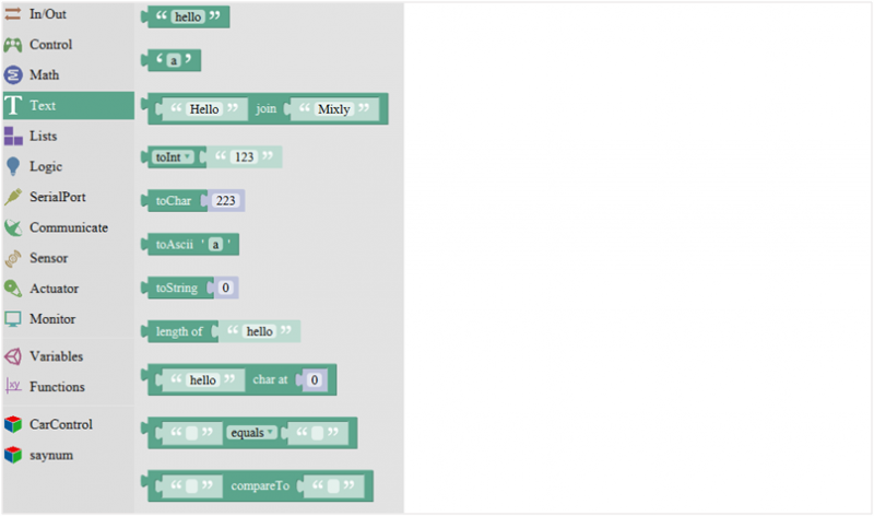
===Text Block=== | |||
<br>[[Image:3.5.png|800px|frameless]]<br> | |||
{| width="80%" cellspacing="0" border="1" | |||
|- | |||
! align="center" scope="col" | No. | |||
! align="center" scope="col" | BLOCK ICON | |||
! align="center" scope="col" | DEFINITION | |||
|- | |||
| align="center" | 1 | |||
| align="center" | <br>[[Image:3.4-1.png|800px|frameless]]<br> | |||
| align="center" | A number | |||
|- | |||
| align="center" | 2 | |||
| align="center" | <br>[[Image:3.3-2.png|800px|frameless]]<br> | |||
| align="center" | Click to select the Arithmetic Operators: | |||
[https://www.arduino.cc/reference/en/language/structure/arithmetic-operators/subtraction/ '''+(addition); -(subtraction)''']; | |||
[https://www.arduino.cc/reference/en/language/structure/arithmetic-operators/multiplication/ '''x (Multiplication); ÷ (division)''']; | |||
[https://www.arduino.cc/reference/en/language/structure/bitwise-operators/bitwisexor/ '''% (remainder); ^ (bitwise xor)'''] | |||
|- | |||
| align="center" | 3 | |||
| align="center" | <br>[[Image:3.3-3.png|800px|frameless]]<br> | |||
| align="center" | Click to select the [https://www.arduino.cc/reference/en/language/structure/bitwise-operators/bitwiseand/ '''& (bitwise end)''']; [https://www.arduino.cc/reference/en/language/structure/bitwise-operators/bitwiseor/ '''l (bitwise or)''']; [https://www.arduino.cc/reference/en/language/structure/bitwise-operators/bitshiftleft/ '''<< (bitshift left)''']; [https://www.arduino.cc/reference/en/language/structure/bitwise-operators/bitshiftright/ '''>> (bitshift right)'''] | |||
|- | |||
| align="center" | 4 | |||
| align="center" | <br>[[Image:3.3-4.png|800px|frameless]]<br> | |||
| align="center" | Click to select the [https://www.arduino.cc/reference/en/language/functions/trigonometry/sin/ '''sin''']; [https://www.arduino.cc/reference/en/language/functions/trigonometry/cos/ '''cos''']; '''tan; asin; acos; atan; ln; log10; e^; 10^;''' [https://www.arduino.cc/reference/en/language/structure/compound-operators/increment/ '''++ (increment)'''] ; | |||
[https://www.arduino.cc/reference/en/language/structure/compound-operators/decrement/ '''-- (decrement)'''] | |||
|- | |||
| align="center" | 5 | |||
| align="center" | <br>[[Image:3.3-5.png|800px|frameless]]<br> | |||
| align="center" | Click to select the '''Round; Ceil; Floor; abs; sq; sqrt''' | |||
'''Round:''' Returns the integer part a number using around. | |||
'''Ceil:''' Returns the integer part a number using ceil. | |||
'''Floor:''' Returns the integer part a number using floor. | |||
'''abs:''' Return the absolute value of a number. | |||
'''sq:''' Return the square of a number. | |||
'''sqrt:''' Return the square root of a number. | |||
|- | |||
| align="center" | 6 | |||
| align="center" | <br>[[Image:3.3-6.png|800px|frameless]]<br> | |||
| align="center" | If select the '''max''', returns the larger number; | |||
if select the '''min''', returns the smaller number. | |||
|- | |||
| align="center" | 7 | |||
| align="center" | <br>[[Image:3.3-7.png|800px|frameless]]<br> | |||
| align="center" | Initialize the random seed | |||
|- | |||
| align="center" | 8 | |||
| align="center" | <br>[[Image:3.3-8.png|800px|frameless]]<br> | |||
| align="center" | Return a random integer between the two specified limits, inclusive. | |||
|- | |||
| align="center" | 9 | |||
| align="center" | <br>[[Image:3.3-9.png|800px|frameless]]<br> | |||
| align="center" | Constrain a number to be between the specified limits (inclusive). | |||
(generally used to constrain an analog value read from sensor) | |||
|- | |||
| align="center" | 10 | |||
| align="center" | <br>[[Image:3.3-10png|800px|frameless]]<br> | |||
| align="center" | Map a number from the first interval to the second interval. | |||
(For instance, potentiometer-controlled servo, map the range of potentiometer (0, 1023) to the angle of servo (0, 180)). | |||
|- | |||
|} | |||
Revision as of 09:20, 23 August 2018
Introduction for Mixly
Mixly is a free open-source graphical Arduino programming software, based on Google’s Blockly graphical programming framework, and developed by Mixly Team@ BNU.
It is a free open-source graphical programming tool for creative electronic development; a complete support ecosystem for creative e-education; a stage for maker educators to realize their dreams.
Although there is an Ardublock graphical programming software launched by Arduino official, Ardublock is not perfect enough, and many common functions cannot be realized.
The figure below shows the functional comparison between Ardublock and Mixly.
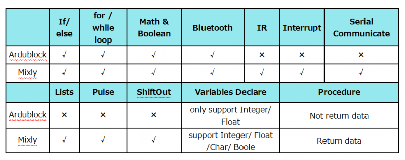
It can be said that Mixly is the most versatile and smoothest Arduino graphical programming software, which can replace the Arduino programming tool IDE.
Design Concept and User Groups
Design Concept
(1) Usability
Mixly is designed to be completely green. Currently Mixly supports win, ubuntu, mac. Windows users can download the Mixly package directly from the Internet, and unzip it to run on Windows XP and above (download link is attached below).
(2) Simplicity
Mixly uses the Blockly graphical programming engine to replace complex text manipulation with graphical building blocks, providing a good foundation for beginners to get started quickly.
① Use the different color icons to represent different types of functional blocks, very convenient for users to classify.
② Provide default options in the composite function block to effectively reduce the number of user drags.
③ Integrate all the features of the software in the same interface.
④ Provide the reference tutorial and code examples.
(3) Functionality
It has versatile functions. Mixly can almost implement all the functions that Arduino IDE has. Support all official development boards of arduino.
(4) Continuity
The goal of the graphical programming system is definitely not to replace the original text programming method, but to better understand the programming principles and program thinking through graphical programming, and lay the foundation for future text programming.
It is also the design philosophy for Mixly. More continuous content has been added to the design of the software to protect the user's learning outcomes. To be specific, it includes the introduction of variable types, the consistency of text programming as much as possible in the design of the module, and the support of both graphical and text programming.
(5) Ecological
The most important design concept of Mixly is its ecological feature, which can distinguish it from other Arduino graphical programming.
In order to achieve sustainable development, Mixly is designed to allow manufacturers to develop their own unique modules (currently supports DfRobot, StartLab, MakeBlock, Sense, Seeed, Lubot. But users require JavaScript programming foundation to make this part of the module).
It also allows users directly use Mixly's graphical programming function to generate common modules (such as LED digital display, buzzer broadcast, etc. Users are able to make this part of the module only using Mixly).
Both of the two kinds of modules mentioned above can be imported into the Mixly system through the "Import" function, thereby realizing the user's own value in the popularity of Mixly software.
User Groups
From the above design concept, it can be seen that Mixly is suitable for primary and secondary school students to cultivate programming thinking. It is also available for quick programming when creating a work. Of course, it is good for those lovely friends who don't want to learn text programming, but want to do some small works with intelligent control.
Interface Functions of Mixly
System Functions
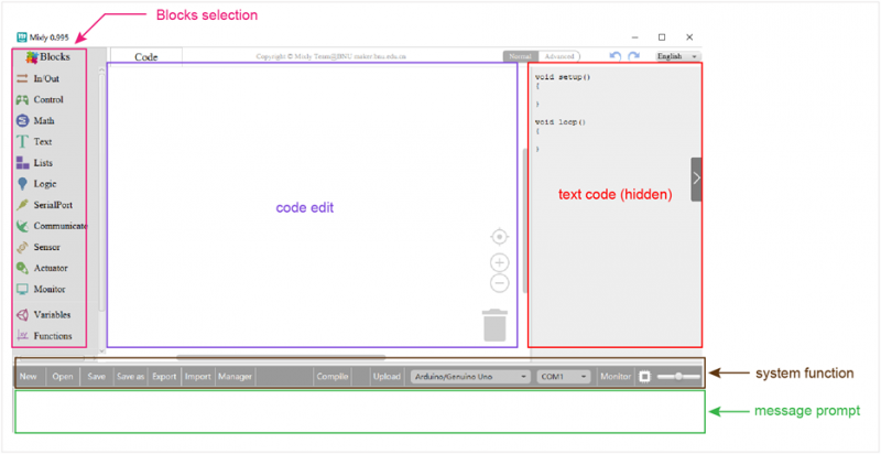
Look at the main interface of Mixly, it includes five parts, that is, Blocks selection, code edit, text code (hidden), system function and message prompt area. Shown below.
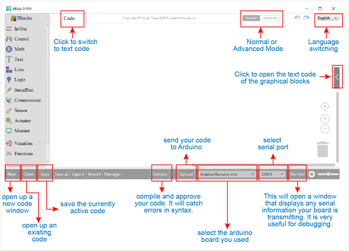
Some common functions:
Through this interface, you can complete the code compile、upload、save and manage. It support four remove methods: drag it left out code window, or drag to Recycle Bin, delete key, or right-click to delete block. It supports four languages: English、Español (Spanish)、中文简体(Chinese Simplified)、中文繁体(Chinese Traditional).
In/Out Block
For example
Connect your Arduino Uno board, then follow the steps below to light the Pin13 led on Arduino UNO.
File:3.2 led D13.png
Control Block
| No. | BLOCK ICON | DEFINITION |
|---|---|---|
| 1 |  |
Initialization (run only once) |
| 2 |  |
End the program, means the program will stop running when use this block. |
| 3 |  |
Delay function, click to select ms or us
(pause the program for the amount of time (in milliseconds) specified as parameter. There are 1000 milliseconds in a second.) |
| 4 |  |
if_do function (first evaluate a value be true or false, if a value is true, then do some statement.
You can click the blue gear icon to select the else if block or else block.) |
| 5 |  |
switch function. You can click the blue gear icon to select the case block or default block. (used to evaluate several programs then execute the corresponding function matched with program.) |
| 6 |  |
Equal to for statement. |
| 7 | 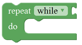 |
A while loop statement. |
| 8 |  |
break function, used to exit from the containing loop. |
| 9 |  |
millis() function, returns the system running time since the program started.
(The unit can be ms (milliseconds) or μs(microsecond)). |
| 10 | File:3.3-10png |
Timer interrupt function, that is, set a trigger interrupt for the amount of time (in milliseconds) specified as parameter. |
| 11 |  |
Timer interrupt start block |
| 12 |  |
Timer interrupt stop block |
For example
Compile and upload the program below to your Arduino board, you should see Pin13 LED on Arduino UNO continue to flash.(with an interval of 1s, equal to 1000ms)
File:3.3 flash.png
Math Block
| No. | BLOCK ICON | DEFINITION |
|---|---|---|
| 1 |  |
A number |
| 2 |  |
Click to select the Arithmetic Operators:
+(addition); -(subtraction); x (Multiplication); ÷ (division); % (remainder); ^ (bitwise xor) |
| 3 |  |
Click to select the & (bitwise end); l (bitwise or); << (bitshift left); >> (bitshift right) |
| 4 |  |
Click to select the sin; cos; tan; asin; acos; atan; ln; log10; e^; 10^; ++ (increment) ; |
| 5 |  |
Click to select the Round; Ceil; Floor; abs; sq; sqrt
Round: Returns the integer part a number using around. Ceil: Returns the integer part a number using ceil. Floor: Returns the integer part a number using floor. abs: Return the absolute value of a number. sq: Return the square of a number. sqrt: Return the square root of a number. |
| 6 |  |
If select the max, returns the larger number;
if select the min, returns the smaller number. |
| 7 |  |
Initialize the random seed |
| 8 |  |
Return a random integer between the two specified limits, inclusive. |
| 9 |  |
Constrain a number to be between the specified limits (inclusive).
(generally used to constrain an analog value read from sensor) |
| 10 | File:3.3-10png |
Map a number from the first interval to the second interval.
(For instance, potentiometer-controlled servo, map the range of potentiometer (0, 1023) to the angle of servo (0, 180)). |
Text Block
| No. | BLOCK ICON | DEFINITION |
|---|---|---|
| 1 |  |
A number |
| 2 |  |
Click to select the Arithmetic Operators:
+(addition); -(subtraction); x (Multiplication); ÷ (division); % (remainder); ^ (bitwise xor) |
| 3 |  |
Click to select the & (bitwise end); l (bitwise or); << (bitshift left); >> (bitshift right) |
| 4 |  |
Click to select the sin; cos; tan; asin; acos; atan; ln; log10; e^; 10^; ++ (increment) ; |
| 5 |  |
Click to select the Round; Ceil; Floor; abs; sq; sqrt
Round: Returns the integer part a number using around. Ceil: Returns the integer part a number using ceil. Floor: Returns the integer part a number using floor. abs: Return the absolute value of a number. sq: Return the square of a number. sqrt: Return the square root of a number. |
| 6 |  |
If select the max, returns the larger number;
if select the min, returns the smaller number. |
| 7 |  |
Initialize the random seed |
| 8 |  |
Return a random integer between the two specified limits, inclusive. |
| 9 |  |
Constrain a number to be between the specified limits (inclusive).
(generally used to constrain an analog value read from sensor) |
| 10 | File:3.3-10png |
Map a number from the first interval to the second interval.
(For instance, potentiometer-controlled servo, map the range of potentiometer (0, 1023) to the angle of servo (0, 180)). |
