KS0221 keyestudio Ultimate Starter Kit for Raspberry Pi: Difference between revisions
Keyestudio (talk | contribs) |
Keyestudio (talk | contribs) |
||
| Line 576: | Line 576: | ||
=== Lesson 5: LED Chasing Effect === | === Lesson 5: LED Chasing Effect === | ||
'''1. Introduction''' <br> | |||
This lesson is expanded on the basis of lesson 2. We are going to control three LED lights’ on and off by controlling three I/O ports of Raspberry Pi, so as to achieve the flowing water light phenomenon. | |||
'''2. Hardware Required''' <br> | |||
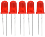
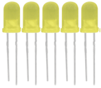
* Red LED*3 <br> | |||
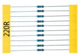
* 220Ω Resistor*3 <br> | |||
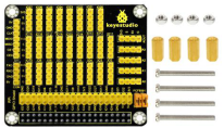
* RPI GPIO Shield*1 <br> | |||
* Breadboard*1 <br> | |||
* 40 Pin Colorful Jumper Wires*1 <br> | |||
* USB Cable*1 <br> | |||
* Raspberry Motherboard*1 <br> | |||
* Jumper Wires*Several <br> | |||
'''3. Connection Diagram''' <br> | |||
<br>[[File:Lesson 5.png|500px|frameless|thumb]]<br> | |||
'''4. Programming''' <br> | |||
'''a.''' Use winSCP to put the '''lesson5_LED_Chasing_Effect''' into the lesson folder of raspberry system. <br> | |||
'''b.''' In the terminal input '''cd lesson5_LED_Chasing_Effect''' to enter the folder. <br> | |||
'''c.''' In the terminal execute '''make''' ,to generate an LED_Chasing_Effect executable file inside the folder. <br> | |||
'''d.''' Wiring as the above diagram, then enter the lesson5_LED_Chasing_Effect folder, execute '''sudo ./LED_Chasing_Effect''' at the terminal. It can achieve the effect of flowing water light. <br> | |||
'''e.''' Ctrl + c can exit the processing program. | |||
<br>[[File:Lesson5-.png|500px|frameless|thumb]]<br> | |||
'''5. Sample Code''' <br> | |||
<pre> | |||
#include <wiringPi.h> | |||
int main() | |||
{ | |||
wiringPiSetup(); | |||
char i; | |||
for(i=1;i<4;i++) | |||
{ | |||
pinMode(i,OUTPUT); | |||
} | |||
while(1) | |||
{ | |||
for (i=1;i<4;i ++) | |||
{ | |||
digitalWrite(i, LOW);// set I/O pins as “low” | |||
delay(200); // delay | |||
} | |||
for (i=1;i<4;i ++) | |||
{ | |||
digitalWrite(i, HIGH);// set I/O pins as “high” | |||
delay(200); // delay | |||
} | |||
} | |||
} | |||
</pre> | |||
=== Lesson 6: Button-controlled LED === | === Lesson 6: Button-controlled LED === | ||
=== Lesson 7: Passive Buzzer === | === Lesson 7: Passive Buzzer === | ||
Revision as of 16:13, 29 December 2017
keyestudio Ultimate Starter Kit for Raspberry Pi
Kit Introduction
Raspberry Pi is a delicate card computer. This is a starter kit of Raspberry Pi, very suitable for zero-based raspberry pi enthusiasts. Through this kit, you can learn more about the knowledge of linux operating system, as well as C, python and other language programming based on the debian system of Raspberry Pi. This kit also provides you with some related sensors and modules applied to the Raspberry Pi.
We offer richer learning materials that allow you to learn about Raspberry Pi from scratch. The learning materials include the installation and usage of the Raspberry Pi related system, where also offer you the learning courses of Raspberry Pi collocated with some commonly used sensors and modules. It would be better If you are an arduino hobbyist because arduino and Raspberry Pi are the best partners. You can make more creative DIY works via arduino strong community support and rich third-party library resources, integrating into Raspberry Pi's powerful function support to motivate your creativity and inspiration!
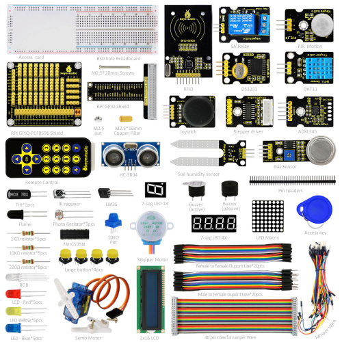
Kit List
Kit Contents
Lesson 1: Hello World
Lesson 2: LED Blinking
Lesson 3: Breathing LED
Lesson 4: Traffic Light
Lesson 5: LED Chasing Effect
Lesson 6: Button-controlled LED
Lesson 7: Passive Buzzer
Lesson 8: Active Buzzer
Lesson 9: Responder
Lesson 10: Flame Sensor
Lesson 11: Ball Tilt Sensor
Lesson 12: IR Remote Control
Lesson 13: 1-digit LED Segment Display
Lesson 14: 74HC595
Lesson 15: 4-digit LED Segment Display
Lesson 16: LED Matrix Display
Lesson 17: 1602 LCD
Lesson 18: RGB LED
Lesson 19: 9g Servo Control
Lesson 20: ULN2003 Stepper Motor
Lesson 21: Photo Resistor
Lesson 22: LM35 Temp Sensor
Lesson 23: pcf8591
Lesson 24: PIR Motion Sensor
Lesson 25: MQ-2 Analog Gas Sensor
Lesson 26: ADXL345 Acceleration Module
Lesson 27: Ultrasonic Sensor
Lesson 28: Joystick Module
Lesson 29: 5V Relay
Lesson 30: DHT11 Temp and Humidity Sensor
Lesson 31: Soil Humidity Sensor
Lesson 32: DS3231 Clock Module
System Programming & Corresponding Tool Library Installation
1. Format the TFT card:
a. Plug the TFT card into the USB port through the card reader, open and install the SDFormatter tool in tool folders we provided. Open the tool as the figure shown below:
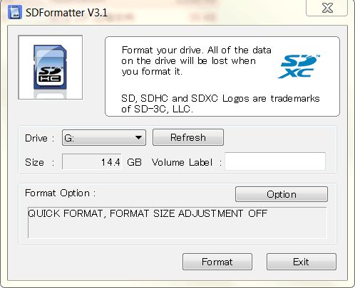
Tool Website: https://www.sdcard.org/downloads/formatter_4/index.html
b. The Driver in the upper figure: G is the TFT card just inserted. If you have several other TFT cards inserted in the computer, you can pass the drop-down menu to select the TFT card that needs to be formatted. And then click "Format",it will automatically format the TFT card. The formatting process will pop up the warning as shown below, then click OK.
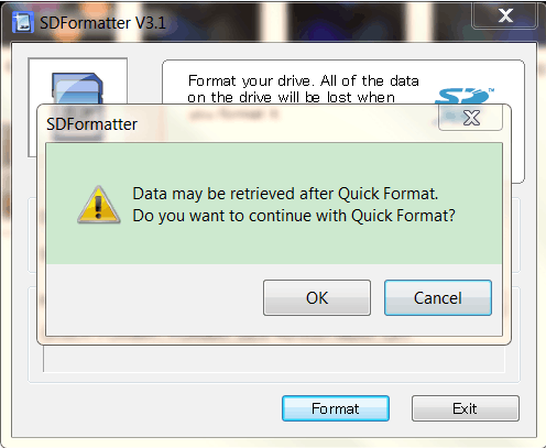
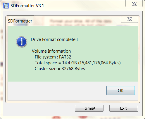
c. The picture below shows the successful format of the TFT card:
2. Program Raspberry Mirror Image:
a. Open the Win32DiskImager in tool folder we provided, open the tool as the following figure shown:
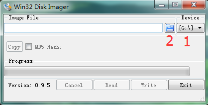
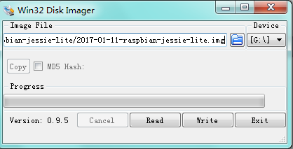
b. Click marked 1 to select the formatted TFT card, then click marked 2 to choose the system image file "2017-01-11-raspbian-jessie-lite" in the raspberry image folder we provided. The figure shown as below:
Raspberry Pi Download Address:https://www.raspberrypi.org/downloads/
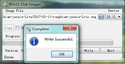
c. The above steps are configured well and click “Write”, it will automatically program the raspberry mirror image to the TFT card, and you need to wait for a few minutes in this process. Below shows the Write Successful. Then click “OK “ to unplug the TFT card.
Log into Raspberry
1. Log into Raspberry via SSH
a. Insert TFT card burning well the system into Raspberry board. Internet interface of the motherboard is connected to LAN via the network cable, and the mini USB port on the motherboard is powered by an external power supply.
Then, use Advanced IP Scanner software,click  ,find the corresponding IP address of the raspberry pi, as shown below:

When logging in by SSH, you first need to put an ssh file in the system root directory, as shown below:
![]()
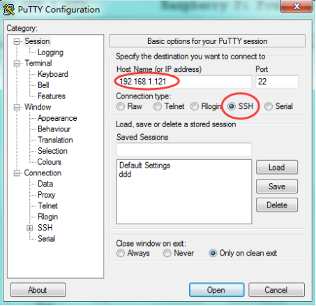
b. Open the PUTTY tool in the folder tool, only set two places of red circle as the figure shown below, the other places not to be set, and then click "Open" to log in.
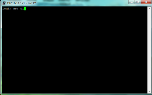
Username for the initial login in Raspberry system: pi
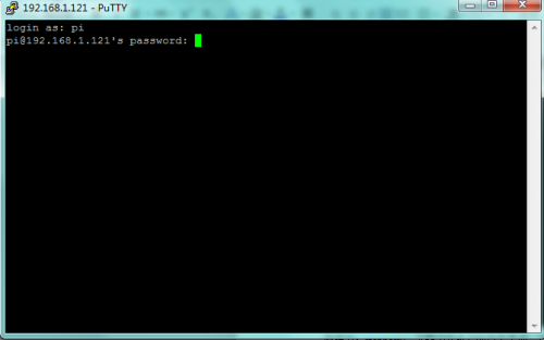
Password: raspberry
Logging in Raspberry system for the first time, it is best to expand the root partition to the entire TFT card, then on the terminal please input: sudo raspi-config
It will appear the following window after execution:
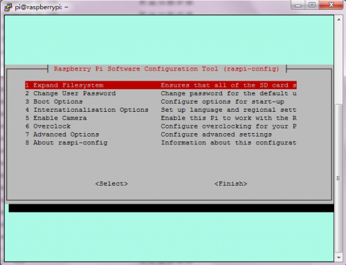
Then, select 1 Expand Filesystem through the keyboard’s "↑↓"key, and click “Enter” key on the keyboard. Then through the "→ ←"key to select “Finish”, and click the “Enter” key on the keyboard. Finally, pop up the following window, then click “Yes”.
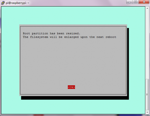
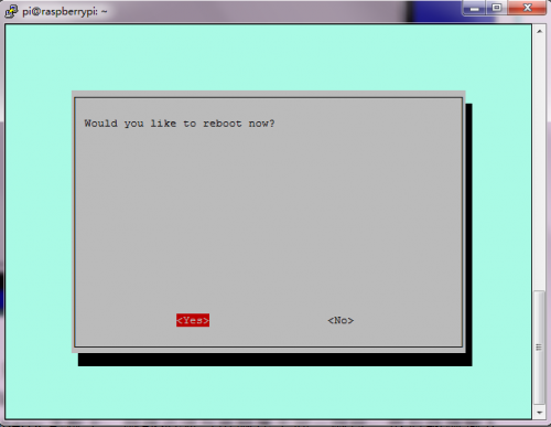
After click Yes, it has rebooted the Raspberry, so you just need to re-login it.
2. Using WinSCP to transfer file between PC host and Raspberry
a. Plug the network cable of the router into the Raspberry motherboard, and network cable must belong to the same network segment with the computer.
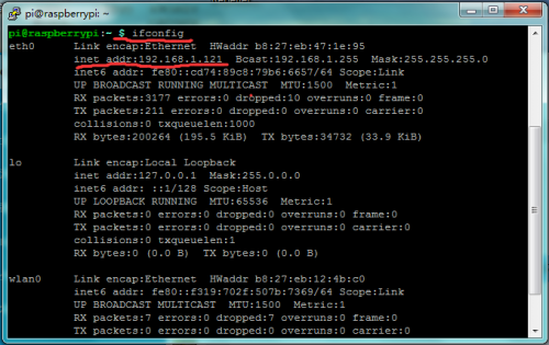
Then input ifconfig command in the terminal to check the Raspberry’s IP, and the IP at this moment is 192.168.1.121 as shown in the following figure:
b. Open the folder tool where provides a WinSCP installation package, then install and open the application program, the window interface shown as the figure below:
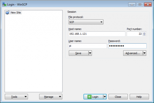
c. File protocol is SCP; Host name is Raspberry’s IP address; Default port number is 22; Username is pi; Password is raspberry.
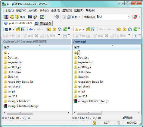
Then click “Login”, if the login process appears prompts, click “Yes”. Appearing the below figure means successfully log in WinSCP.
3. Install Wiringpi
a. Wiringpi is a library file for raspberry to control IO port, in which integrates I2C library, SPI library, UART library, software PWM library and more.
The relevant library function folder provides the compression package of wiringpi library file.
Or you can download it on the official website: https://projects.drogon.net/raspberry-pi/wiringpi/download-and-install/
Use winSCP to put the wiringPi-b0a60c3.tar of PC into the pi user folder of raspberry system, as shown in the figure below:
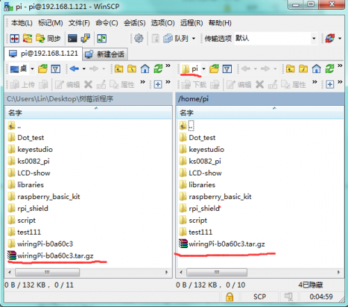
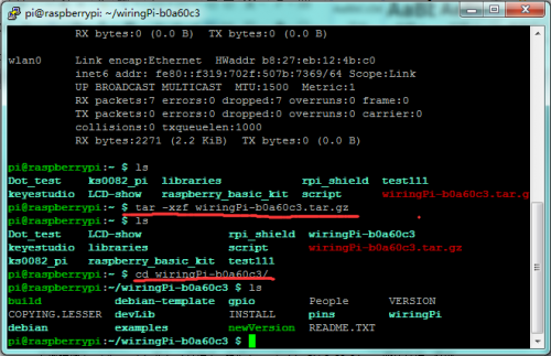
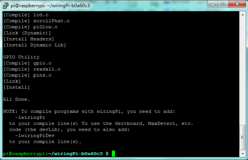
b. In the terminal input cd/home/pi to enter pi folder; execute tar-xzf wiringPi-b0a60c3.tar.gz to unzip the file, getting wiringPi-b0a60c3 folder; in the terminal input cd wiringPi-b0a60c3 command, execute ./build to install wiringpi. The window interface below shows the successful installation:
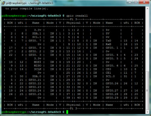
c. To see whether the wiringpi installation is successful, in the terminal execute gpio readall command.
Pop up the below window interface means installation successfully.
Learning Courses
Lesson 1: Hello World
1. Introduction
Since it is the first contact with Raspberry Pi, you just need a raspberry motherboard without other auxiliary components to display "Hello World!"
2. Hardware Required
- USB Cable * 1
- Raspberry Motherboard * 1
3. Programming
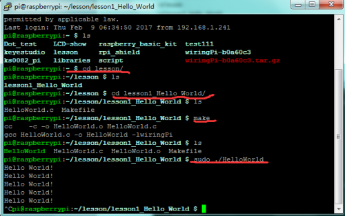
a. In the terminal input cd / home / pi and mkdir lesson to build lesson folder.
b. Use winSCP to put Lesson1_Hello_world into the lesson folder of raspberry system.
c. In the terminal execute cd lesson and cd lesson1_Hello_World to enter the folder.
d. In the terminal execute make, generating a HelloWorld executable file in the folder.
e. In the terminal execute sudo. / HelloWorld to run the file, the terminal will print Hello World! as the figure shown below.
f. Ctrl + c exits the processing program.
4. Sample Code
#include <wiringPi.h>
#include <stdio.h>

int main()

{
  wiringPiSetup();
//      printf("Hello World!\n");

 for(;;)
 {
 printf("Hello World!\n");
  delay(1000);

 }
  }
5. Special Instruction
lesson1_Hello_World folder has a Makefile file. Code as below:
HelloWorld:HelloWorld.o
gcc HelloWorld.c -o HelloWorld -lwiringPi
Makefile rule:
Target(target): Prerequisite(prerequiries)...
<tab> Command(command)
Target is usually the name of the file to be generated; Prerequiries is the material to generate the target; <tab> Command is a command to execute a target.
When executing the make command in the folder, the system's compiler will generate the executable HelloWorld file according to the instructions in the Malefile file. Executing HelloWorld file, more Makefile knowledge please refer to the relevant information.
Lesson 2: LED Blinking
1. Introduction
LED small light experiment is one of the more basic experiments. In this lesson, we will use I/O port of Raspberry Pi to simply control red LED blinking.
2. Hardware Required
- Red LED *1
- 220ΩResistor*1
- RPI GPIO Shield*1
- 40 Pin Colorful Jumper Wires*1
- Breadboard*1
- USB Cable*1
- Raspberry Motherboard*1
- Jumper Wires*Several
4. Programming
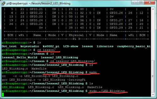
a. Use winSCP to put the lesson2_LED_Blinking into the lesson folder of raspberry system.
b. In the terminal input cd lesson2_LED_Blinking to enter the folder.
c. In the terminal execute make, generating an LED_Blinking executable file inside the folder.
d. Wiring as the above diagram, then enter the lesson2_LED_Blinking folder, execute sudo ./LED_Blinking on the terminal, and you can see the LED blinking effect.
e. Ctrl + c can exit the processing program.
5. Sample Code
#include <wiringPi.h>
int main()
{
  wiringPiSetup();

  {
        pinMode(1,OUTPUT);
  }

  while(1)
  {
        digitalWrite(1,HIGH);
        delay(500);
        digitalWrite(1,LOW);
        delay(500);
  }

}
Lesson 3: Breathing LED
1. Introduction
In the last lesson, we have controlled the LED light’s on and off by controlling the I/O port of Raspberry Pi to output high and low levels.
This time we come to control LED light’s brightness, and finally make the effect of breathing light.
2. Hardware Required
- Red LED *1
- 220Ω Resistor*1
- RPI GPIO Shield*1
- 40 Pin Colorful Jumper Wires*1
- Breadboard*1
- USB Cable*1
- Raspberry Motherboard*1
- Jumper Wires*Several
4. Programming
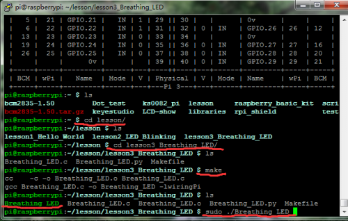
a. Use winSCP to put the lesson3_Breathing_LED into the lesson folder of raspberry system.
b. In the terminal input cd lesson3_Breathing_LED to enter the folder.
c. In the terminal execute make, to generate a Breathing_LED executable file inside the folder.
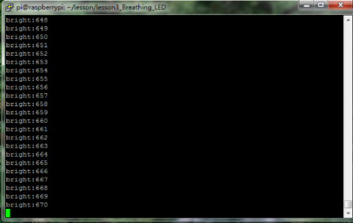
d. Wiring as the above diagram, then enter the lesson3_Breathing_LED folder, execute sudo ./Breathing_LED at the terminal.
It can achieve the effect of breathing light, and display the corresponding data in the terminal.
e. Ctrl + c can exit the processing program.
5. Sample Code
 #include <stdio.h>
 #include <stdlib.h>
 #include <stdint.h>
 #include <wiringPi.h>
 #define LED 1

int main(void)
{
   int bright;
    printf("Raspberry Pi wiringPi PWM test program\n");
    if (wiringPiSetup() == -1)
     {
        printf("GPIO setup error!\n");
         exit(1);
    }
    pinMode(LED,PWM_OUTPUT);
     while(1)
    {
     for (bright = 0; bright < 1024; ++bright)
         {
            pwmWrite(LED,bright);
            printf("bright:%d\n",bright);
             delay(3);
        }
    for (bright = 1023; bright >= 0; --bright)
        {
             pwmWrite(LED,bright);
             printf("bright:%d\n",bright);
             delay(3);
         }
       }
     return 0;
 }
Lesson 4: Traffic Light
1. Introduction
This lesson is expanded on the basis of lesson 2. We are going to control three LED lights’ on and off by controlling three I/O ports of Raspberry Pi, so as to simulate the traffic light phenomenon.
2. Hardware Required
- LED - Red *1
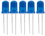
- LED - Blue*1
- LED - Yellow*1
- 220Ω Resistor*3
- RPI GPIO Shield*1
- Breadboard*1
- 40 Pin Colorful Jumper Wires*1
- USB Cable*1
- Raspberry Motherboard*1
- Jumper Wires*Several
4. Programming
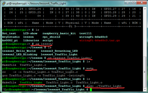
a. Use winSCP to put the lesson4_Traffic_Light into the lesson folder of raspberry system.
b. In the terminal input cd lesson4_Traffic_Light to enter the folder.
c. In the terminal execute make ,to generate a Traffic_Light executable file inside the folder.
d. Wiring as the above diagram, then enter the lesson4_Traffic_Light folder, execute sudo ./Traffic_Light at the terminal. It can achieve the effect of traffic light.
e. Ctrl + c can exit the processing program.
5. Sample Code
#include <wiringPi.h>
int main()
{
  wiringPiSetup();
  char i;
  char j;
  for(i=1;i<4;i++)
  {
        pinMode(i,OUTPUT);
  }
  while(1)
  {
   digitalWrite(1, HIGH);//// turn on blue LED
   delay(5000);// wait 5 seconds
   digitalWrite(1, LOW); // turn off blue LED
   for(j=0;j<3;j++) // blinks for 3 times
   {
   delay(500);// wait 0.5 second
   digitalWrite(2, HIGH);// turn on yellow LED
   delay(500);// wait 0.5 second
   digitalWrite(2, LOW);// turn off yellow LED
   }
   delay(500);// wait 0.5 second
   digitalWrite(3, HIGH);// turn on red LED
   delay(5000);// wait 5 second
   digitalWrite(3, LOW);// turn off red LED
   }
}
Lesson 5: LED Chasing Effect
1. Introduction
This lesson is expanded on the basis of lesson 2. We are going to control three LED lights’ on and off by controlling three I/O ports of Raspberry Pi, so as to achieve the flowing water light phenomenon.
2. Hardware Required
- Red LED*3
- 220Ω Resistor*3
- RPI GPIO Shield*1
- Breadboard*1
- 40 Pin Colorful Jumper Wires*1
- USB Cable*1
- Raspberry Motherboard*1
- Jumper Wires*Several
4. Programming
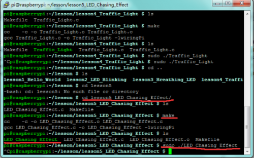
a. Use winSCP to put the lesson5_LED_Chasing_Effect into the lesson folder of raspberry system.
b. In the terminal input cd lesson5_LED_Chasing_Effect to enter the folder.
c. In the terminal execute make ,to generate an LED_Chasing_Effect executable file inside the folder.
d. Wiring as the above diagram, then enter the lesson5_LED_Chasing_Effect folder, execute sudo ./LED_Chasing_Effect at the terminal. It can achieve the effect of flowing water light.
e. Ctrl + c can exit the processing program.
5. Sample Code
#include <wiringPi.h>
int main()
{
  wiringPiSetup();
  char i;
  for(i=1;i<4;i++)
  {
    pinMode(i,OUTPUT);
  }

  while(1)
  {
    for (i=1;i<4;i ++)
   {
    digitalWrite(i, LOW);// set I/O pins as “low”
     delay(200);        // delay
   }
   for (i=1;i<4;i ++)
   {
     digitalWrite(i, HIGH);// set I/O pins as “high”
     delay(200);       // delay
   }
  }
}
Lesson 6: Button-controlled LED
Lesson 7: Passive Buzzer
Lesson 8: Active Buzzer
Lesson 9: Responder
Lesson 10: Flame Sensor
Lesson 11: Ball Tilt Sensor
Lesson 12: IR Remote Control
Lesson 13: 1-digit LED Segment Display
Lesson 14: 74HC595
Lesson 15: 4-digit LED Segment Display
Lesson 16: LED Matrix Display
Lesson 17: 1602 LCD
Lesson 18: RGB LED
Lesson 19: 9g Servo Control
Lesson 20: ULN2003 Stepper Motor
Lesson 21: Photo Resistor
Lesson 22: LM35 Temp Sensor
Lesson 23: pcf8591
Lesson 24: PIR Motion Sensor
Lesson 25: MQ-2 Analog Gas Sensor
Lesson 26: ADXL345 Acceleration Module
Lesson 27: Ultrasonic Sensor
Lesson 28: Joystick Module
Lesson 29: 5V Relay
Lesson 30: DHT11 Temp and Humidity Sensor
Lesson 31: Soil Humidity Sensor
Lesson 32: DS3231 Clock Module
Documents
Datasheet PDF:
https://drive.google.com/open?id=15oq3qPcp3FARMIDrGwGDmp9mMVlmk3gE
SDFormatter Tool:
https://www.sdcard.org/downloads/formatter_4/index.html
Raspberry Pi Download:
https://www.raspberrypi.org/downloads/
Install Wiringpi:
https://projects.drogon.net/raspberry-pi/wiringpi/download-and-install/
Download Mirror Image File:
https://www.raspberrypi.org/downloads/raspbian/
