Ks0099 keyestudio EASY plug Control Board: Difference between revisions
Keyestudio (talk | contribs) |
Keyestudio (talk | contribs) No edit summary |
||
| Line 9: | Line 9: | ||
The warnings and wrong operations possible cause dangerous. | The warnings and wrong operations possible cause dangerous. | ||
== Specifications == | == Specifications == | ||
| Line 96: | Line 92: | ||
} | } | ||
[[Category: Arduino Board]] | |||
[[Category: EASY Plug Control]] | |||
[[Category: | |||
Revision as of 13:46, 11 August 2016
Introduction
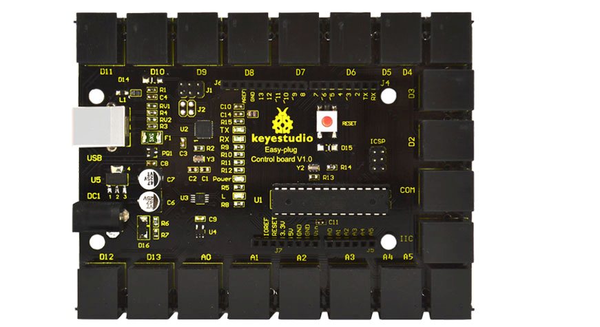
Keyestudio Easy-plug control board is a microcontroller board based on the ATmega328P-PU. It has 14 digital input/outputs (of which 6 can be used as PWM outputs), 6 analog inputs, a 16 MHz quartz crystal, a USB connection, a power jack, an ICSP header and a reset button. It contains everything needed to support the microcontroller; simply connect it to a computer with a USB cable or power it with a AC-to-DC adapter or battery to get started.You can tinker with your UNO without worrying too much about doing something wrong, worst case scenario you can replace the chip for a few dollars and start over again.
For convenience of wire connection, we simplify pins GND and VCC into each plug, so you only need one wire to connect a module, no need to separately connect the VCC and GND. The pins on the original UNO are all redesigned into plug interface. On the board, you can find ports D2-D13, A0 to A5, an IIC port and a COM port. All in one simple plug.].
Cautions
The warnings and wrong operations possible cause dangerous.
Specifications
| Microcontroller core: | ATmega328P-PU |
|---|---|
| Working voltage: | +5V |
| External input voltage: | +7V~+12V(suggest) |
| External input voltage ( extremum ): | +6V≤ Vin ≤ +20V |
| Digital signal I/O interface: | 14 (of which 6 provide PWM output) |
| Analog signal input interface: | 6 |
| DCI/O interface current: | 20 mA |
| FlashMemory: | 32KB (ATmega328) of which 0.5 KB used by bootloader |
| SRAM static storage capacity: | 2KB |
| EEPROM storage capacity: | 1 KB |
| EEPROM storage capacity: | 16 MHz |
Board test
Following is a board test example called “Hello World!”.
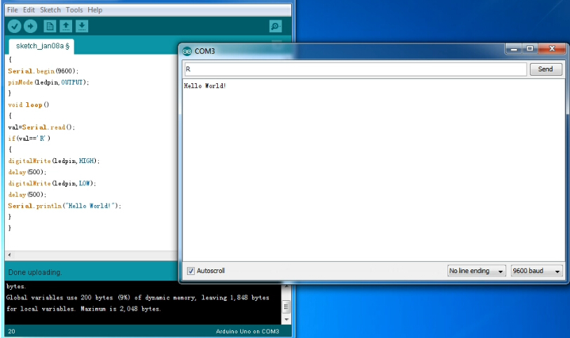
First, open Arduino IDE. In this example sketch, we program Arduino to display “Hello World!” in serial monitor when it receives a specific character string “R”; also the on-board D13 LED will blink once each time it receives “R”.
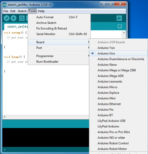
First, set up board; In “Tools”, select “Arduino Uno”.
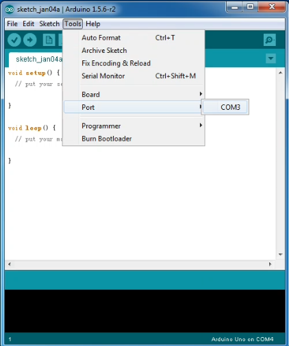
Next, set up COM port; In “Tools”, select “COM3”.
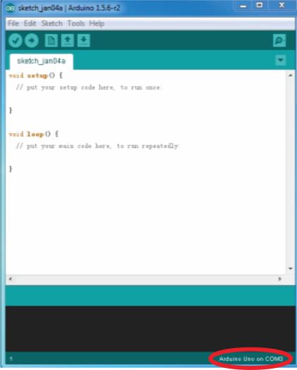
After selection, you can see indicated area is the same with settings in “Device manager”.
Copy the example sketch and paste it to the IDE; click “Verify ” to check compiling mistakes; click “Upload ” to upload the program to the board.
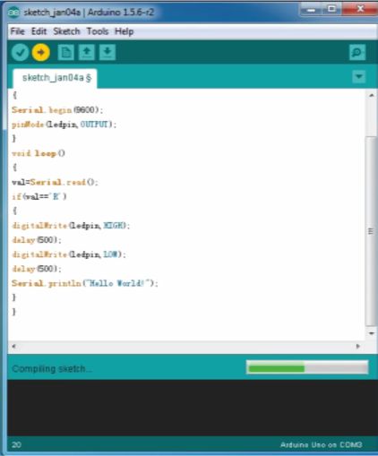
After uploading is done, open “serial monitor ”; enter “R”; click “Send”, the serial monitor will display “Hello World!” and the D13 LED will blink once.
Programming
int val; int ledpin=13 void setup() { Serial.begin(9600); pinMode(ledpin,OUTPUT); } void loop() { val=Serial.read(); if(val=='R') { digitalWrite(ledpin,HIGH); delay(500); digitalWrite(ledpin,LOW); delay(500); Serial.println("Hello World!"); } }