Ks0248 keyestudio Leonardo R3 Development Board: Difference between revisions
Jump to navigation
Jump to search
Keyestudio (talk | contribs) |
Keyestudio (talk | contribs) |
||
| Line 1: | Line 1: | ||
==Introduction == | ==Introduction == | ||
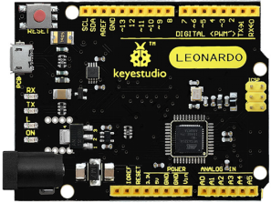
The keyestudio Leonardo R3 development board is our newest easy-to-use open-source controller. It has twenty-three digital I/O ports, seven PWM ports and twelve analog input ports. Compared with other versions of Arduino using separate USB - Serial conversion chips, it only uses a single Atmega32u4 to achieve USB communication and control. The Atmega32u4's native support USB feature also enables Leonardo to simulate a mouse and keyboard. | The keyestudio Leonardo R3 development board is our newest easy-to-use open-source controller. It has twenty-three digital I/O ports, seven PWM ports and twelve analog input ports. Compared with other versions of Arduino using separate USB - Serial conversion chips, it only uses a single Atmega32u4 to achieve USB communication and control. The Atmega32u4's native support USB feature also enables Leonardo to simulate a mouse and keyboard. | ||
<br>[[File:Ks0248.png|500x|frameless|thumb]]<br> | <br>[[File:Ks0248.png|500x|frameless|thumb]]<br> | ||
Revision as of 09:02, 18 October 2017
Introduction
The keyestudio Leonardo R3 development board is our newest easy-to-use open-source controller. It has twenty-three digital I/O ports, seven PWM ports and twelve analog input ports. Compared with other versions of Arduino using separate USB - Serial conversion chips, it only uses a single Atmega32u4 to achieve USB communication and control. The Atmega32u4's native support USB feature also enables Leonardo to simulate a mouse and keyboard.
Specification
- Controller: ATmega32u4
- Working frequency: 16 MHz
- Working voltage: 5V
- Input voltage (recommended) : 7-12v
- Digital I/O port: 23
- PWM channel: 7
- Analog input: 12
- Maximum allowable current of 5V digital/analog port: 40 mA
- Maximum allowable current of 3.3V digital/analog port: 50 mA
- Flash Memory: 32 KB (ATmega32u4) of which 4 KB used by boot loader
- SRAM: 2.5 KB (ATmega32u4)
- EEPROM: 1 KB (ATmega32u4)
- Digital IO port: 23 (D0 - D13, D14-MISO, D15-SCK, D16-MOSI, D18-23 [A0-A5])
- Analog input: 12 (A0 - A5, D4 - A6, D6 - A7, D8 - A8, D9 - A9, D10 - A10, D12-A11)
- Serial communication: D0 (RX) and D1 (TX)
- IIC communication: D2 (SDA) and D3 (SCL)
- External interrupt: D3 (interrupt 0), D2 (interrupt 1), D0 (interrupt 2), D1 (interrupt 3) and D7 (interrupt 4)
- PWM port: D3, D5, D6, D9, D10, D11 and D13
- SPI: ICSP pins.Support SPI communication by using the SPI library. It is important to note that SPI pins do not connect to any number I/O pins like UNO, they can only work on the ICSP port.This means that if your expansion board has no ICSP pin connected to the 6 feet, it will not work.
- LED: 13. There is a built-in LED on the digital pin 13. When the pins are high level, LED is bright;when the pins are low level,the LED is not bright.
Resources
Datasheet:
http://www.keyestudio.com/files/index/download/id/1500424728/
Get One Now
http://www.keyestudio.com/keyestudio-leonardo-r3-development-board.html
