Ks0254 keyestudio Sim800c Shield: Difference between revisions
Keyestudio (talk | contribs) |
Keyestudio (talk | contribs) |
||
| (25 intermediate revisions by the same user not shown) | |||
| Line 1: | Line 1: | ||
[[image:KS0254.png|thumb|700px|right|keyestudio Sim800c Shield]] | |||
<br> | |||
==Introduction== | ==Introduction== | ||
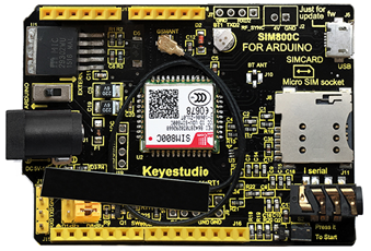
This is a GPRS / GSM Arduino | This is a GPRS/GSM expansion board for Arduino. <br> | ||
It is controlled by the AT command, you can | The shield supports the frequency of EGSM 900MHz /DCS 1800MHz and GSM850 MHz /PCS 1900MHz, integrated with GPRS, DTMF and other functions. <br> | ||
It also supports DTMF. When enable the DTMF function, get the character feedback converted from the pressed button during the call, which can be used for remote control.<br> | |||
It is controlled by the AT command, you can directly start the function through the computer serial port and Arduino motherboard. <br> | |||
The SIM800C GPRS shield has a built-in SIM800H chip from SIMCom, with good stability. | |||
== | <br> | ||
* Power Supply<Vin> | ==Specifications== | ||
* Low power consumption | * Power Supply <Vin>: 7-12V | ||
* Low power consumption: 0.7mA current in sleep mode | |||
* Low battery consumption (100mA @ 7V-GSM mode) | * Low battery consumption (100mA @ 7V-GSM mode) | ||
* GSM 850/900/1800/1900MHz | * GSM 850/900/1800/1900MHz | ||
| Line 14: | Line 19: | ||
* GPRS mobile station class B | * GPRS mobile station class B | ||
* GSM phase 2/2 + standard | * GSM phase 2/2 + standard | ||
* Class 4 ( | * Class 4 (2W @ 850/900 MHz) | ||
* Class 1 ( | * Class 1 (1W @ 1800 / 1900MHz) | ||
* | * Controlling via AT command | ||
* USB /Arduino control switch | * USB /Arduino control switch | ||
* | * Serial baud rate self-adaption | ||
* Support DTMF | * Support DTMF | ||
* LED indicator | * LED indicator for power supply status, network status and operating mode. | ||
<br> | |||
==Technical Details== | |||
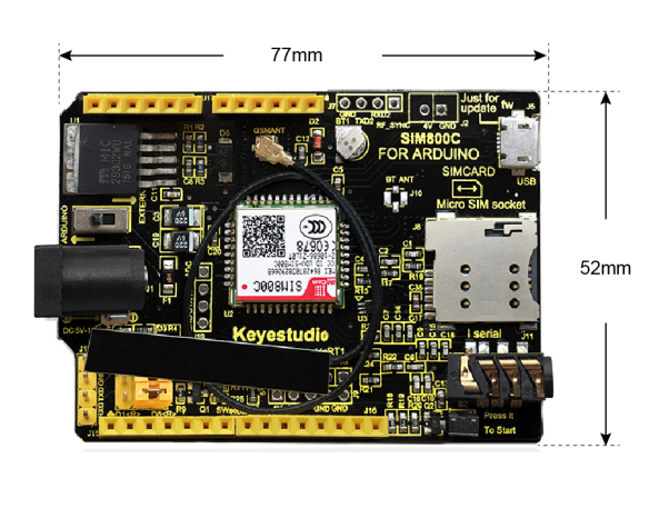
* Dimensions: 77mm x 52mm x 27mm | |||
* Weight: 26g | |||
* Antenna length: 180mm | |||
<br>[[File:图片1- ks0254.png|700px|frameless|thumb]]<br> | |||
<br> | |||
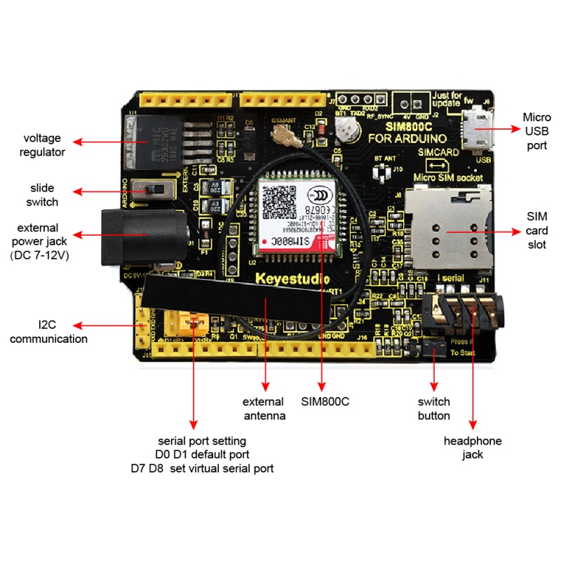
==PINOUT== | |||
<br>[[File:KS0254 PINOUT.jpg|800px|frameless|thumb]]<br> | |||
<br> | |||
==Test Code== | |||
1)For default serial ports RXD(D0) and TXD(D1): call up | |||
<pre> | <pre> | ||
************************************************ | |||
void setup() | void setup() | ||
{ | { | ||
pinMode(13, OUTPUT); | |||
pinMode(9, OUTPUT); //D9 is SIM900 turn on pin | |||
digitalWrite(9,HIGH); | |||
delay(1000); | |||
digitalWrite(9,LOW); | |||
delay(15000); | |||
Serial.begin(9600); | |||
} | } | ||
void loop() | void loop() | ||
{ | { | ||
// | Serial.print("ATD15812345678;\r");//15812345678 your dialing phone number | ||
delay(100000); | |||
/ | // Serial.println("ATH"); | ||
delay(200000); | |||
} | |||
</pre> | |||
'''How to Use''' | |||
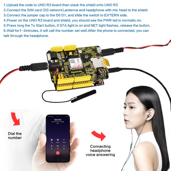
1.Burn the above code onto keyestudio V4.0 board, stack shield on it, and connect SIM card(support 2G internet), Ethernet cable and earphone to shield.<br> | |||
2.Connect the jumper caps of shield to D0 and D1. DIP switch is dialed to EXTERN end, V4.0 board and shield are provided with power, alternatively, dial to ARDUINO end to supply power for V4.0 board which also provides power for shield.<br> | |||
3.The PWR LED of V4.0 board stays on, long press“To Start” button, then release button when the STA LED is always on and NET LED flashes.<br> | |||
4.Wait for 1 or 2 minutes and dial number 15912345678, after connection, you could call up by earphone or cellphone.<br> | |||
<br>[[File:KS0254 SIM800C.jpg|600px|frameless|thumb]]<br> | |||
2)For default serial ports RXD(D0) and TXD(D1): Send message | |||
<pre> | |||
************************************************ | |||
void sendMeg() | |||
{ | |||
Serial.println("AT"); | |||
delay(2000); | |||
Serial.println("AT+CMGF=1"); | |||
delay(2000); | |||
Serial.println("AT+CMGS=\"15812345678\"");//modify into your own number | |||
delay(2000); | |||
Serial.print("ABCDEFGHIJKLMN\r\n");//fill in content | |||
delay(2000); | |||
Serial.write(0x1A); | |||
} | } | ||
void setup() { | |||
// put your setup code here, to run once: | |||
Serial.begin(9600); | |||
} | } | ||
void loop() { | |||
// put your main code here, to run repeatedly: | |||
delay(15*1000); | |||
sendMeg(); | |||
} | |||
************************************************ | |||
</pre> | |||
Code to Note: | |||
1.Serial.println("AT+CMGS=\"15812345678\"");//modify into your own number | |||
2.Serial.print("ABCDEFGHIJKLMN\r\n");//fill in content | |||
'''How to Use''' | |||
1. Burn the above code onto keyestudio V4.0 board, stack shield on it, and connect SIM card(support 2G internet), Ethernet cable to shield.<br> | |||
2. Connect the jumper caps of shield to D0 and D1. DIP switch is dialed to EXTERN end, V4.0 board and shield are provided with power, alternatively, dial to ARDUINO end to supply power for V4.0 board which also provides power for shield.<br> | |||
3. The PWR LED of V4.0 board stays on. Long press “To Start” button, then release button if the STA LED is always on and NET LED flashes.<br> | |||
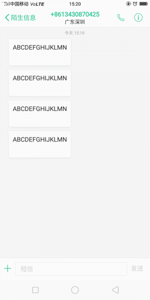
4.Wait for a while, the cellphone will receiver the message from SIM900<br> | |||
<br>[[File:09然485345.png|300px|frameless|thumb]]<br> | |||
// | 3)For adding serial ports RXD(D6) and TXD(D7): call up | ||
void | <pre> | ||
************************************************ | |||
#include <SoftwareSerial.h> | |||
SoftwareSerial SIM900(6, 7); // define serial port PIN | |||
void SIM900_Start() | |||
{ | |||
digitalWrite(9, HIGH); | |||
delay(2000); | |||
digitalWrite(9, LOW); | |||
delay(5000); | |||
} | |||
void Call_Phone() | |||
{ | |||
SIM900.println("ATD15812345678;"); // the numbers behind ATD is your phone number to dial. | |||
delay(100); | |||
SIM900.println("ATD15812345678;"); | |||
delay(30000); // wait for 30 seconds... | |||
SIM900.println("ATH"); // hang up | |||
} | |||
void setup() | |||
{ | { | ||
pinMode(9, OUTPUT); | |||
SIM900.begin(19200); //set baud rate | |||
SIM900_Start(); | |||
delay(20000); // wait for SIM900 to work | |||
} | } | ||
void loop() | |||
{ | |||
Call_Phone(); | |||
do | |||
{ | |||
} | |||
while(1); | |||
} | |||
************************************************ | |||
</pre> | </pre> | ||
'''How to Use''' | |||
1.Burn the above code onto keyestudio V4.0 board, stack shield on it, and connect SIM card(support 2G internet), Ethernet cable and earphone to shield.<br> | |||
2.Connect the jumper caps of shield to D6 and D7. DIP switch is dialed to EXTERN end, V4.0 board and shield are provided with power, alternatively, dial to ARDUINO end to supply power for V4.0 board which also provides power for shield.<br> | |||
3.The PWR LED of V4.0 board stays on. Long press “To Start” button, then release button if the STA LED is always on and NET LED flashes.<br> | |||
4.Wait for 1 or 2 minutes and dial number 15912345678, after connection, you could call up by earphone or cellphone. <br> | |||
<br> | |||
==Package Includes== | |||
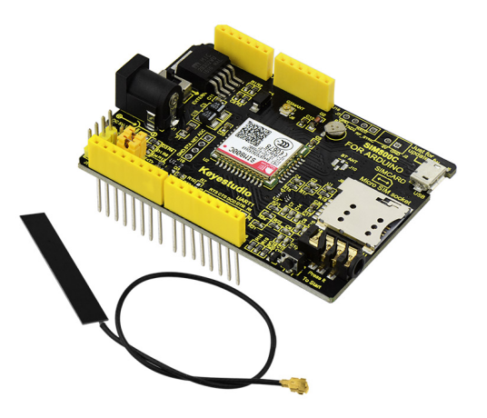
* Keyestudio SIM800C Shield *1pcs | |||
* Antenna line *1pcs | |||
<br>[[File:图片2- ks0254.png|700px|frameless|thumb]]<br> | |||
<br> | |||
==Resources == | ==Resources == | ||
''' | '''Download the code and libraries:'''<br> | ||
https://fs.keyestudio.com/KS0254 | |||
https:// | |||
<br> | |||
==Get One Now == | ==Get One Now == | ||
'''Official Website''' | *[https://www.keyestudio.com/keyestudio-sim800c-shield-for-arduino-uno-r3-and-mega-2560-gprs-gsm-p0306.html '''Official Website'''] | ||
*[https://www.aliexpress.com/store/product/Keyestudio-SIM800C-Shield-for-Arduino-UNO-R3-and-Mega-2560-GPRS-GSM/1452162_32830468111.html?spm=2114.12010612.8148356.28.3e4b276fmFnCXj '''Shop on Aliexpress'''] | |||
*[https://www.ebay.com/itm/Keyestudio-GPRS-SIM800C-GSM-Module-DTMF-Development-Board-for-Arduino/132763216691?hash=item1ee94deb33:g:iPYAAOSw8lhbWy~x '''Shop on eBay'''] | |||
*[https://www.amazon.com/dp/B07B2G3YFB '''Shop on amazon'''] | |||
[[Category: | [[Category: Shield]] | ||
Latest revision as of 14:14, 6 January 2021
Introduction
This is a GPRS/GSM expansion board for Arduino.
The shield supports the frequency of EGSM 900MHz /DCS 1800MHz and GSM850 MHz /PCS 1900MHz, integrated with GPRS, DTMF and other functions.
It also supports DTMF. When enable the DTMF function, get the character feedback converted from the pressed button during the call, which can be used for remote control.
It is controlled by the AT command, you can directly start the function through the computer serial port and Arduino motherboard.
The SIM800C GPRS shield has a built-in SIM800H chip from SIMCom, with good stability.
Specifications
- Power Supply <Vin>: 7-12V
- Low power consumption: 0.7mA current in sleep mode
- Low battery consumption (100mA @ 7V-GSM mode)
- GSM 850/900/1800/1900MHz
- GPRS multi-slot class 1 ~ 12
- GPRS mobile station class B
- GSM phase 2/2 + standard
- Class 4 (2W @ 850/900 MHz)
- Class 1 (1W @ 1800 / 1900MHz)
- Controlling via AT command
- USB /Arduino control switch
- Serial baud rate self-adaption
- Support DTMF
- LED indicator for power supply status, network status and operating mode.
Technical Details
- Dimensions: 77mm x 52mm x 27mm
- Weight: 26g
- Antenna length: 180mm
PINOUT
Test Code
1)For default serial ports RXD(D0) and TXD(D1): call up
************************************************
void setup()
{
  pinMode(13, OUTPUT);
  pinMode(9, OUTPUT); //D9 is SIM900 turn on pin
  digitalWrite(9,HIGH);
  delay(1000);
  digitalWrite(9,LOW);
  delay(15000);
  Serial.begin(9600);
}

void loop()
{
  Serial.print("ATD15812345678;\r");//15812345678 your dialing phone number
  delay(100000);
//  Serial.println("ATH");
  delay(200000);
}
How to Use
1.Burn the above code onto keyestudio V4.0 board, stack shield on it, and connect SIM card(support 2G internet), Ethernet cable and earphone to shield.
2.Connect the jumper caps of shield to D0 and D1. DIP switch is dialed to EXTERN end, V4.0 board and shield are provided with power, alternatively, dial to ARDUINO end to supply power for V4.0 board which also provides power for shield.
3.The PWR LED of V4.0 board stays on, long press“To Start” button, then release button when the STA LED is always on and NET LED flashes.
4.Wait for 1 or 2 minutes and dial number 15912345678, after connection, you could call up by earphone or cellphone.
2)For default serial ports RXD(D0) and TXD(D1): Send message
************************************************
  void sendMeg()
  {
  Serial.println("AT");
  delay(2000);
  Serial.println("AT+CMGF=1");
  delay(2000);
  Serial.println("AT+CMGS=\"15812345678\"");//modify into your own number
  delay(2000);
  Serial.print("ABCDEFGHIJKLMN\r\n");//fill in content
  delay(2000);
  Serial.write(0x1A);
 }
void setup() {
  // put your setup code here, to run once:
  Serial.begin(9600);
}
void loop() {
  // put your main code here, to run repeatedly:
  delay(15*1000);
  sendMeg();
}

************************************************
Code to Note: 1.Serial.println("AT+CMGS=\"15812345678\"");//modify into your own number 2.Serial.print("ABCDEFGHIJKLMN\r\n");//fill in content
How to Use
1. Burn the above code onto keyestudio V4.0 board, stack shield on it, and connect SIM card(support 2G internet), Ethernet cable to shield.
2. Connect the jumper caps of shield to D0 and D1. DIP switch is dialed to EXTERN end, V4.0 board and shield are provided with power, alternatively, dial to ARDUINO end to supply power for V4.0 board which also provides power for shield.
3. The PWR LED of V4.0 board stays on. Long press “To Start” button, then release button if the STA LED is always on and NET LED flashes.
4.Wait for a while, the cellphone will receiver the message from SIM900
3)For adding serial ports RXD(D6) and TXD(D7): call up
************************************************
#include <SoftwareSerial.h>
SoftwareSerial SIM900(6, 7); // define serial port PIN
void SIM900_Start()
{
  digitalWrite(9, HIGH);
  delay(2000);
  digitalWrite(9, LOW);
  delay(5000);
}
void Call_Phone()
{
  SIM900.println("ATD15812345678;"); // the numbers behind ATD is your phone number to dial.
  delay(100);
  SIM900.println("ATD15812345678;");
  delay(30000);            // wait for 30 seconds...
  SIM900.println("ATH");   // hang up
}
void setup()
{
  pinMode(9, OUTPUT);
  SIM900.begin(19200);   //set baud rate
  SIM900_Start();
  delay(20000);  // wait for SIM900 to work
}
void loop()
{
  Call_Phone();
  do
  {
  }
  while(1);
}
************************************************
How to Use
1.Burn the above code onto keyestudio V4.0 board, stack shield on it, and connect SIM card(support 2G internet), Ethernet cable and earphone to shield.
2.Connect the jumper caps of shield to D6 and D7. DIP switch is dialed to EXTERN end, V4.0 board and shield are provided with power, alternatively, dial to ARDUINO end to supply power for V4.0 board which also provides power for shield.
3.The PWR LED of V4.0 board stays on. Long press “To Start” button, then release button if the STA LED is always on and NET LED flashes.
4.Wait for 1 or 2 minutes and dial number 15912345678, after connection, you could call up by earphone or cellphone.
Package Includes
- Keyestudio SIM800C Shield *1pcs
- Antenna line *1pcs
Resources
Download the code and libraries:
https://fs.keyestudio.com/KS0254
