Ks0281 Keyestudio Reprap Stepper Motor Driver: Difference between revisions
Keyestudio (talk | contribs) |
Keyestudio (talk | contribs) No edit summary |
||
| Line 1: | Line 1: | ||
<br> | |||
==Keyestudio Reprap Stepper Motor Driver== | ==Keyestudio Reprap Stepper Motor Driver== | ||
<br>[[File:Ks0281.png|500px|frameless|thumb]]<br> | <br>[[File:Ks0281.png|500px|frameless|thumb]]<br> | ||
<br> | |||
==Introduction== | ==Introduction== | ||
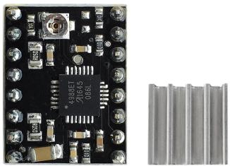
This stepper motor driver is powered by A4988, a DMOS microstep driver with converter and overcurrent protection. It is available in full, half, 1/4, 1/8 and 1/16 stepping modes to operate bipolar stepper motors with output drive performance up to 35 V and ± 2A. The A4988 includes a fixed turn-off time current regulator that operates in slow or mixed decay mode. | This stepper motor driver is powered by A4988, a DMOS microstep driver with converter and overcurrent protection. It is available in full, half, 1/4, 1/8 and 1/16 stepping modes to operate bipolar stepper motors with output drive performance up to 35 V and ± 2A. <br> | ||
The converter is the key to easy implementation of the A4988. As long as the "step" input carries in a pulse, you can drive the motor to produce micro-step. There is no need for phase sequence tables, high frequency control lines or complex interface programming. The A4988 interface is ideal for complex microprocessors that are not available or overloaded. | The A4988 includes a fixed turn-off time current regulator that operates in slow or mixed decay mode.<br> | ||
The converter is the key to easy implementation of the A4988. As long as the "step" input carries in a pulse, you can drive the motor to produce micro-step.<br> | |||
There is no need for phase sequence tables, high frequency control lines or complex interface programming. The A4988 interface is ideal for complex microprocessors that are not available or overloaded.<br> | |||
<br>[[File:Ks0281-3.png|500px|frameless|thumb]]<br> | <br>[[File:Ks0281-3.png|500px|frameless|thumb]]<br> | ||
<br> | |||
==Specification== | ==Specification== | ||
* 1.With only a simple step and direction control interface; | * 1.With only a simple step and direction control interface; | ||
| Line 15: | Line 22: | ||
<br>[[File:KS0281 (8).jpg|500px|frameless|thumb]]<br> | <br>[[File:KS0281 (8).jpg|500px|frameless|thumb]]<br> | ||
<br> | |||
==Setting method of working mode == | ==Setting method of working mode == | ||
<br>[[File:Ks0281-.png| | <br>[[File:Ks0281-.png|600px|frameless|thumb]]<br> | ||
<br> | |||
==Connection Diagram== | ==Connection Diagram== | ||
It needs to connect DC 8-15V between motor power VMOT and GND. | It needs to connect DC 8-15V between motor power VMOT and GND.<br> | ||
<br>[[File:KS0281-5.png|500px|frameless|thumb]]<br> | |||
<br> | <br> | ||
== PINOUTS == | |||
<br>[[File:Ks0281-2.png|500px|frameless|thumb]]<br> | <br>[[File:Ks0281-2.png|500px|frameless|thumb]]<br> | ||
<br> | |||
==Sample Code == | ==Sample Code == | ||
<pre> | <pre> | ||
int dirPin = 7; | int dirPin = 7; | ||
| Line 51: | Line 62: | ||
</pre> | </pre> | ||
<br> | |||
== Result == | == Result == | ||
The selection end MS1, MS2, MS3 of three modes are all connected to GND, that is, full-step mode, and the motor needs 200 stepping values or a stepping 1.8° to turn a round. In the experiment, we first let the stepper motor reverse 8 circles and delay 0.5 seconds; then turn 40 circles and delay 0.5 seconds. If it is an half-step mode, then the number of both positive and reverse circle should be halved. | The selection end MS1, MS2, MS3 of three modes are all connected to GND, that is, full-step mode, and the motor needs 200 stepping values or a stepping 1.8° to turn a round. <br> | ||
In the experiment, we first let the stepper motor reverse 8 circles and delay 0.5 seconds; then turn 40 circles and delay 0.5 seconds. If it is an half-step mode, then the number of both positive and reverse circle should be halved.<br> | |||
<br>[[File:KS0281 (5).jpg|500px|frameless|thumb]]<br> | <br>[[File:KS0281 (5).jpg|500px|frameless|thumb]]<br> | ||
<br> | |||
==Resources== | ==Resources== | ||
'''PDF File:''' <br> | * '''PDF File:''' <br> | ||
https://drive.google.com/open?id= | https://drive.google.com/open?id=1uN9kZW41Spitl2hO5ZaNF5wxg5rZrn_S | ||
* '''Test Code:''' <br> | |||
https://drive.google.com/open?id=1F-_j75AA8Qfo5dg0xlaKK1TBJxeuK9jl | |||
* '''VIDEO:'''<br> | |||
http://video.keyestudio.com/ks0281/ | |||
<br> | |||
==Buy from == | ==Buy from == | ||
http://www.keyestudio.com/keyestudio-reprap-stepper-motor-driver.html\\\ | |||
[[Category: Module]] | [[Category: Module]] | ||
Revision as of 11:38, 24 April 2019
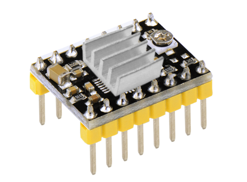
Keyestudio Reprap Stepper Motor Driver
Introduction
This stepper motor driver is powered by A4988, a DMOS microstep driver with converter and overcurrent protection. It is available in full, half, 1/4, 1/8 and 1/16 stepping modes to operate bipolar stepper motors with output drive performance up to 35 V and ± 2A.
The A4988 includes a fixed turn-off time current regulator that operates in slow or mixed decay mode.
The converter is the key to easy implementation of the A4988. As long as the "step" input carries in a pulse, you can drive the motor to produce micro-step.
There is no need for phase sequence tables, high frequency control lines or complex interface programming. The A4988 interface is ideal for complex microprocessors that are not available or overloaded.
Specification
- 1.With only a simple step and direction control interface;
- 2.Five different step modes: full, half, 1/4, 1/8 and 1/16;
- 3.Adjustable potentiometer can adjust the maximum current output, resulting in a higher step rate;
- 4.Automatic current decay mode detection / selection;
- 5.Overheat shutdown circuit, undervoltage lockout, cross current protection;
- 6.Ground short circuit protection and load short circuit protection.
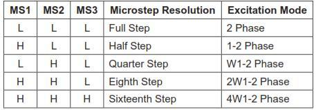
Setting method of working mode
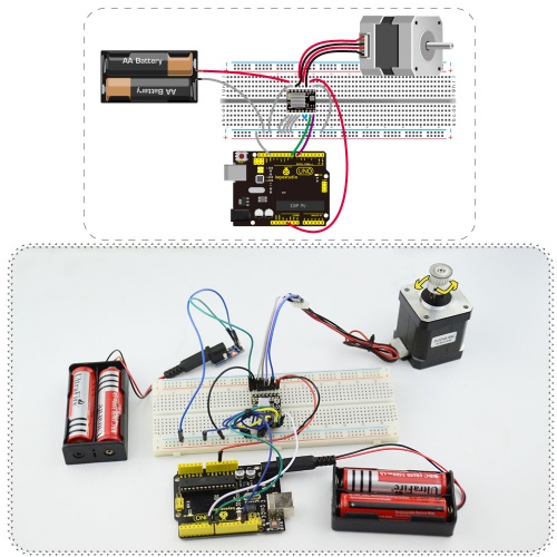
Connection Diagram
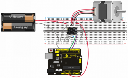
It needs to connect DC 8-15V between motor power VMOT and GND.
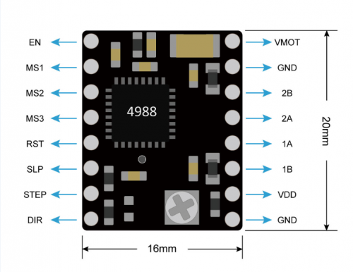
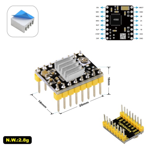
PINOUTS
Sample Code
int dirPin = 7;
int stepperPin = 8;
void setup() {
pinMode(dirPin, OUTPUT);
pinMode(stepperPin, OUTPUT);
}
void step(boolean dir,int steps){
digitalWrite(dirPin,dir);
delay(50);
for(int i=0;i<steps;i++){
digitalWrite(stepperPin, HIGH);
delayMicroseconds(800);
digitalWrite(stepperPin, LOW);
delayMicroseconds(800);
}
}
void loop(){
step(true,1600);
delay(500);
step(false,1600*5);
delay(500);
}
Result
The selection end MS1, MS2, MS3 of three modes are all connected to GND, that is, full-step mode, and the motor needs 200 stepping values or a stepping 1.8° to turn a round.
In the experiment, we first let the stepper motor reverse 8 circles and delay 0.5 seconds; then turn 40 circles and delay 0.5 seconds. If it is an half-step mode, then the number of both positive and reverse circle should be halved.
Resources
- PDF File:
https://drive.google.com/open?id=1uN9kZW41Spitl2hO5ZaNF5wxg5rZrn_S
- Test Code:
https://drive.google.com/open?id=1F-_j75AA8Qfo5dg0xlaKK1TBJxeuK9jl
- VIDEO:
http://video.keyestudio.com/ks0281/
Buy from
http://www.keyestudio.com/keyestudio-reprap-stepper-motor-driver.html\\\
