Ks0313 keyestudio Desktop Mini Bluetooth Smart Car V2.0 Kit: Difference between revisions
Keyestudio (talk | contribs) |
Keyestudio (talk | contribs) |
||
| Line 231: | Line 231: | ||
Let’s move on to the driver installation in the WIN 7 system. | Let’s move on to the driver installation in the WIN 7 system. | ||
*When you connect UNO board to your computer at the first time, right click “Computer” —>“Properties”—> “Device manager”, you can see “Unknown devices”. <br> | |||
First, right click “Computer” —>select “Properties”—> click “Device manager”, you should see an icon for ‘unknown device’ with a little yellow warning triangle next to it. This is your Arduino. <br>[[Image:Driver 1.png|500px|frameless]]<br> | |||
| Line 239: | Line 238: | ||
*You will then be prompted to either ‘Search Automatically for updated driver software’ or ‘Browse my computer for driver software’. | *You will then be prompted to either ‘Search Automatically for updated driver software’ or ‘Browse my computer for driver software’. | ||
In this page, click “Browse my computer for driver software”. <br>[[Image:Driver 3.png|500px|frameless]]<br> | In this page, click “Browse my computer for driver software”. <br>[[Image:Driver 3.png|500px|frameless]]<br> | ||
| Line 253: | Line 252: | ||
*After installation, go to check the “Device manager” again. right click “Computer” —> “Properties”—> “Device manager”, you can see the device shown as below figure. <br>[[Image:Driver 7.png|500px|frameless]]<br> | *After installation, go to check the “Device manager” again. right click “Computer” —> “Properties”—> “Device manager”, you can see the device shown as below figure. <br>[[Image:Driver 7.png|500px|frameless]]<br> | ||
== Example for Using Arduino IDE == | == Example for Using Arduino IDE == | ||
Revision as of 09:10, 29 May 2018
keyestudio keyestudio Desktop Mini Bluetooth Smart Car V2.0 Kit
Overview
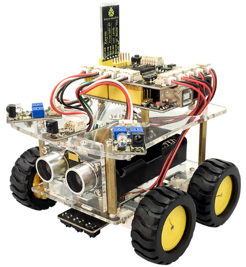
keyestudio 4WD Desktop Mini Bluetooth Smart Car V2.0 Kit is based on microcontroller learning application development system. This smart car is controlled by UNO R3 microcontroller. It can achieve the functions of line tracking, obstacle avoidance, IR remote control, Bluetooth remote control and more. All electronic components of the smart car are soldered with anti-reverse interfaces, making it easy and convenient for you to connect the wires.
This kit also contains plenty of interesting programs, which can help you master the electronic sensor modules and running functions of car. The kit aims to disengage you from boring theories, and you can make further study of microcontroller system development when playing it.
Parameters
- 1) Motor Voltage range: 1-6V; motor shaft length: 10mm; speed: 6.0V 100rpm/min.
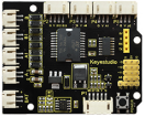
- 2) Motor control is driven by L298P.
- 3) Three groups of line tracking modules, to detect black-white line, with higher accuracy and can also be used for anti-fall control.
- 4) Two groups of obstacle detector modules, to detect whether there are obstacles on the left or right side of smart car; Ultrasonic module is used to detect the distance between ultrasonic and obstacles, forming the smart car’s obstacle avoidance system.
- 5) Bluetooth wireless module can be paired with mobile phone’s Bluetooth to remotely control smart car.
- 6) Infrared receiver module is matched with an infrared remote control to control smart car.
- 7) Can access the external 7 ~ 12V voltage.
Component List
Assembly Steps
Arduino IDE and Driver Installation
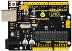
Next, we will introduce the driver installation of keyestudio UNO R3 development board. You can also follow it to install the driver for MEGA2560 R3 development board. The installation method is similar and you can use the same drive file.
Let’s move on to the driver installation in the WIN 7 system.
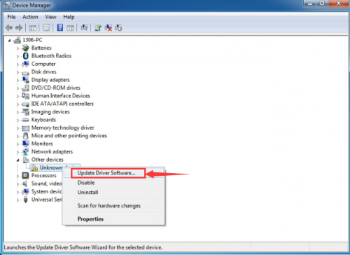
- When you connect UNO board to your computer at the first time, right click “Computer” —>“Properties”—> “Device manager”, you can see “Unknown devices”.
First, right click “Computer” —>select “Properties”—> click “Device manager”, you should see an icon for ‘unknown device’ with a little yellow warning triangle next to it. This is your Arduino. 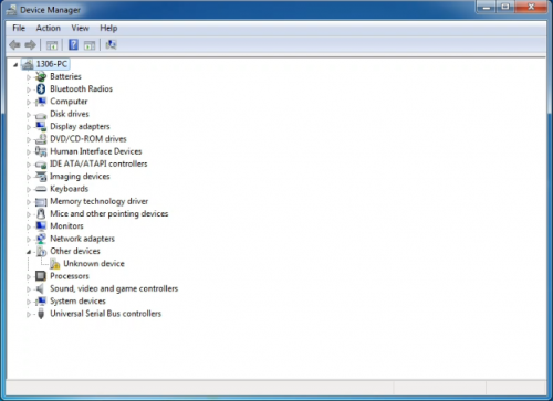
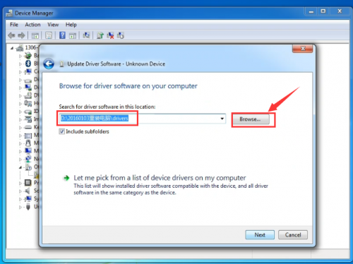
- You will then be prompted to either ‘Search Automatically for updated driver software’ or ‘Browse my computer for driver software’.
In this page, click “Browse my computer for driver software”. 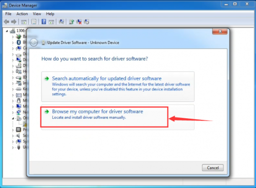
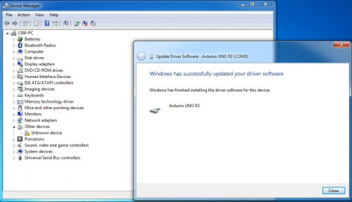
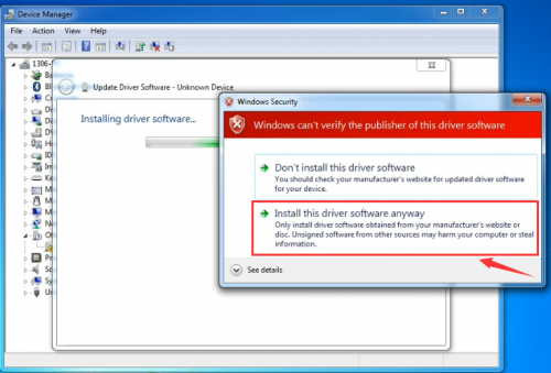
- Click 'Next' and you may get a security warning, if so, allow the software to be installed. Once the software has been installed, you will get a confirmation message.
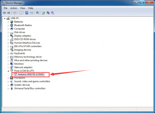
- After installation, go to check the “Device manager” again. right click “Computer” —> “Properties”—> “Device manager”, you can see the device shown as below figure.
Example for Using Arduino IDE
When successfully installing the USB driver for UNO R3 board, you can find the corresponding serial port in Windows Device Manager. Next, we will show you the program “Hello World!” displayed on the serial monitor of Arduino IDE. Here we use the Arduino 1.5.6 version.
Sample Code as below:
Copy and paste the following source code to Arduino IDE.
int val;
int ledpin=13;
void setup()
{
Serial.begin(9600);
pinMode(ledpin,OUTPUT);
}
void loop()
{
val=Serial.read();
if(val=='R')
{
digitalWrite(ledpin,HIGH);
delay(500);
digitalWrite(ledpin,LOW);
delay(500);
Serial.println("Hello World!");
}
}
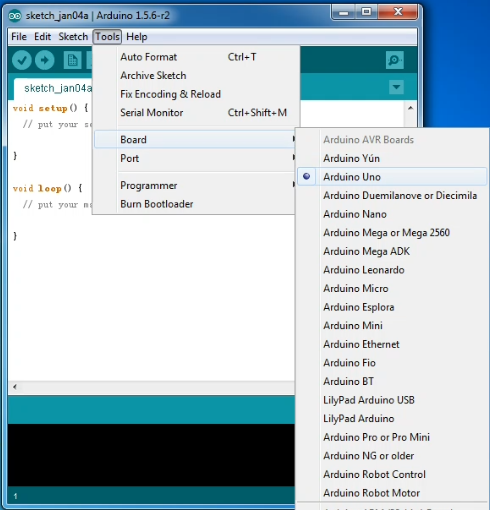
Then,set the Board and COM port, shown below.
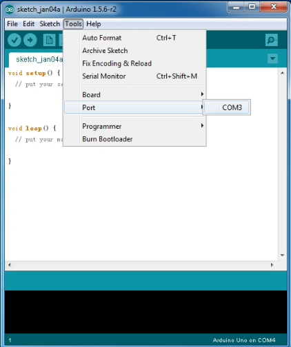
If setting well the board and port, you can see it display on the bottom right corner, which is the same as the Device Manager display.
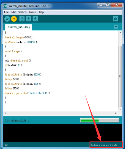
Then, click the verify to compile the sketch, if no mistake, click upload to upload the program.
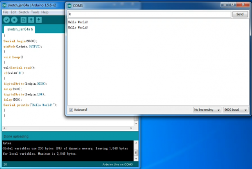
Done uploading, open the serial monitor on the upper right corner and set the baud rate as 9600, enter an “R” and then click “Send”, finally you can see the D13 indicator on the UNO R3 board blinks once, and “Hello World!” is displayed on the serial monitor. Shown below.

Congrats. Your first programming is done well!
