Ks0313 keyestudio Desktop Mini Bluetooth Smart Car V2.0 Kit: Difference between revisions
Keyestudio (talk | contribs) |
Keyestudio (talk | contribs) |
||
| Line 320: | Line 320: | ||
=== 1)Keyestudio quick connectors Motor Drive Shield === | === 1)Keyestudio quick connectors Motor Drive Shield === | ||
<br>[[File:Ks0313-7(1.png|500px|frameless|thumb]]<br> | |||
| Line 339: | Line 342: | ||
'''Connection Diagram''' <br> | '''Connection Diagram''' <br> | ||
<br>[[File:Ks0313-7(2.png|500px|frameless|thumb]]<br> | |||
Revision as of 09:29, 29 May 2018
keyestudio keyestudio Desktop Mini Bluetooth Smart Car V2.0 Kit

Overview
keyestudio 4WD Desktop Mini Bluetooth Smart Car V2.0 Kit is based on microcontroller learning application development system. This smart car is controlled by UNO R3 microcontroller. It can achieve the functions of line tracking, obstacle avoidance, IR remote control, Bluetooth remote control and more. All electronic components of the smart car are soldered with anti-reverse interfaces, making it easy and convenient for you to connect the wires.
This kit also contains plenty of interesting programs, which can help you master the electronic sensor modules and running functions of car. The kit aims to disengage you from boring theories, and you can make further study of microcontroller system development when playing it.
Parameters
- 1) Motor Voltage range: 1-6V; motor shaft length: 10mm; speed: 6.0V 100rpm/min.
- 2) Motor control is driven by L298P.
- 3) Three groups of line tracking modules, to detect black-white line, with higher accuracy and can also be used for anti-fall control.
- 4) Two groups of obstacle detector modules, to detect whether there are obstacles on the left or right side of smart car; Ultrasonic module is used to detect the distance between ultrasonic and obstacles, forming the smart car’s obstacle avoidance system.
- 5) Bluetooth wireless module can be paired with mobile phone’s Bluetooth to remotely control smart car.
- 6) Infrared receiver module is matched with an infrared remote control to control smart car.
- 7) Can access the external 7 ~ 12V voltage.
Component List
| No. | Component | Quantity | Picture |
|---|---|---|---|
| 1 | Keyestudio UNO R3 Main Board | 1 |  |
| 2 | Keyestudio quick connectors motor driver shield | 1 |  |
| 3 | Keyestudio quick connectors IR receiver module | 1 | |
| 4 | Keyestudio quick connectors line tracking sensor | 1 |  |
| 5 | Keyestudio quick connectors 12FN20 motor | 4 |  |
| 6 | Keyestudio quick connectors obstacle detector module | 2 | |
| 7 | Keyestudio quick connectors ultrasonic module | 1 | |
| 8 | keyestudio Bluetooth HC-06 | 1 | |
| 9 | Keyestudio JMFP-4 17-button 86*40*6.5MM yellow (eco-friendly) (no battery) | 1 |  |
| 10 | Double-Connector JST-PH2.0MM-5P 24AWG blue-green-yellow-red-black wire 15CM (reverse direction) | 1 | |
| 11 | Double-Connector JST-PH2.0MM-4P 24AWG green-yellow-red-black wire 8CM (reverse direction) | 1 | |
| 12 | Double-Connector JST-PH2.0MM-3P 24AWG yellow-red-black wire 8CM (reverse direction) | 3 | |
| 13 | Double-Connector JST-PH2.0MM-2P 24AWG red-black wire 160mm | 4 | |
| 14 | Battery holder with JST-PH2.0MM-2P socket lead, black-red lead length 150mm | 1 |  |
| 15 | Screw M2*10MM round head | 10 | |
| 16 | Nut M2 nickle plating | 10 | |
| 17 | Screw M3*10MM round head cross | 9 | |
| 18 | Screw M3*6MM round head | 18 | |
| 19 | Screw M3*8MM flat head | 4 | |
| 20 | Nut M3 nickle plating | 15 |
|
| 21 | Dual-pass M3*40MM Copper Pillar | 4 | |
| 22 | Single-pass M3*8+6MM | 4 | |
| 23 | M3*12MM Copper Pillar | 2 | |
| 24 | N20 motor-dedicated wheel | 4 |  |
| 25 | N20 motor holder white U-type plastic | 4 | |
| 26 | Transparent acrylic panel (3PCS) thickness 3MM | 1 |  |
| 27 | Black-yellow Handle 3*40MM cross screwdriver | 1 | |
| 28 | Lithium Ion Battery Charger 18650 double-cell with plug | 1 |  |
| 29 | 18650 battery pack 3.7V blue 2PCS CS100% | 1 | |
| 30 | USB cable AM/BM transparent blue OD:5.0 L=1m | 1 |
Assembly Steps
Arduino IDE and Driver Installation
When getting the development board, first of all you have to install the Arduino IDE and the driver, and all relevant files can be found on the official website.
The following link includes various systems, various versions of the Arduino IDE and drivers whatever you choose.
https://www.arduino.cc/en/Main/OldSoftwareReleases#1.5.x
Next, we first introduce the installation method of Arduino IDE-1.5.6 version in the Windows system.
The file downloaded is an arduino-1.5.6-r2-windows.zip compression folder, please unzip it to the hard disk. Double-click Arduino-1.5.6 .exe file.
Please refer to the following setup figures:

Click “I Agree”. Then, click “Next”

Next, click “Install”.

Finally, click “Close” after completing the installation.

The figure below shows the Arduino 1.5.6 version:

Next, we will introduce the driver installation of keyestudio UNO R3 development board. You can also follow it to install the driver for MEGA2560 R3 development board. The installation method is similar and you can use the same drive file.
Let’s move on to the driver installation in the WIN 7 system.
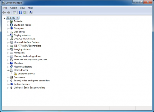
- When you connect UNO board to your computer at the first time, right click “Computer” —>“Properties”—> “Device manager”, you can see “Unknown devices”. First, right click “Computer” —>select “Properties”—> click “Device manager”, you should see an icon for ‘unknown device’ with a little yellow warning triangle next to it. This is your Arduino.

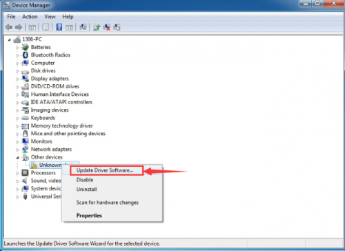
- Right-click on the device and select the top menu option (Update Driver Software...).

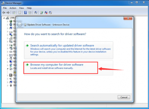
- You will then be prompted to either ‘Search Automatically for updated driver software’ or ‘Browse my computer for driver software’. In this page, click “Browse my computer for driver software”.

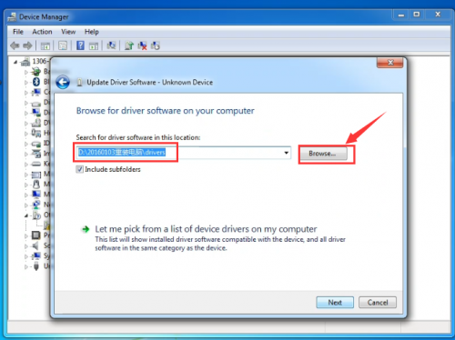
- Select the option to browse and navigate to the drivers folder.

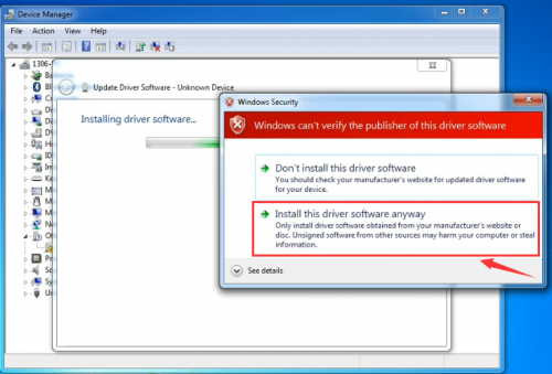
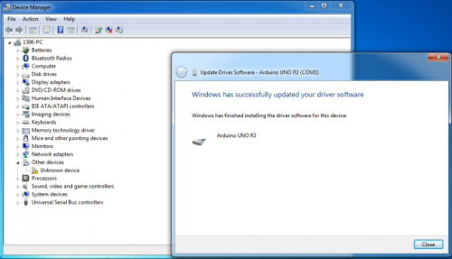
- Click 'Next' and you may get a security warning, if so, allow the software to be installed. Once the software has been installed, you will get a confirmation message.

- Installation completed, click “Close”.

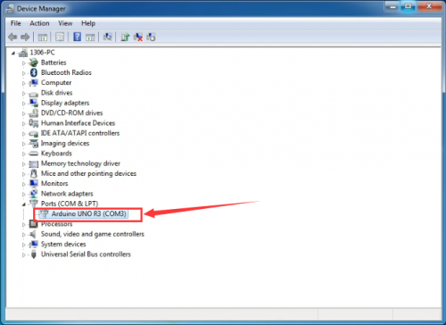
- After installation, go to check the “Device manager” again. right click “Computer” —> “Properties”—> “Device manager”, you can see the device shown as below figure.

Example for Using Arduino IDE
When successfully installing the USB driver for UNO R3 board, you can find the corresponding serial port in Windows Device Manager. Next, we will show you the program “Hello World!” displayed on the serial monitor of Arduino IDE. Here we use the Arduino 1.5.6 version.
Sample Code as below:
Copy and paste the following source code to Arduino IDE.
int val;
int ledpin=13;
void setup()
{
Serial.begin(9600);
pinMode(ledpin,OUTPUT);
}
void loop()
{
val=Serial.read();
if(val=='R')
{
digitalWrite(ledpin,HIGH);
delay(500);
digitalWrite(ledpin,LOW);
delay(500);
Serial.println("Hello World!");
}
}
Then,set the Board and COM port, shown below.


If setting well the board and port, you can see it display on the bottom right corner, which is the same as the Device Manager display.

Then, click the verify to compile the sketch, if no mistake, click upload to upload the program.
Done uploading, open the serial monitor on the upper right corner and set the baud rate as 9600, enter an “R” and then click “Send”, finally you can see the D13 indicator on the UNO R3 board blinks once, and “Hello World!” is displayed on the serial monitor. Shown below.


Congrats. Your first programming is done well!
Projects Details
1)Keyestudio quick connectors Motor Drive Shield

Description
Keyestudio quick connectors motor driver shield is specially designed for this smart car. The driver chip used in this shield is L298P and it comes with a power switch. When stacking the driver shield onto UNO R3 board, after the BAT is powered on, press the POWER button lightly, so external power is supplied to both driver shield and UNO R3 board at the same time.
In order to facilitate wiring, this driver shield comes with an anti-reverse interface. You can use only several wire to connect the motor, power and sensor modules. The Bluetooth interface on this shield is fully compatible with HC-06 Bluetooth module. So you just need to connect HC-06 Bluetooth module to the connector directly.
At the same time, the 2.54 pin header on the shield is reserved for both digital and analog ports of UNO R3 board. This allows you to continue to add other sensors for experiment extension.
Specifications
- 1.Input voltage for Logic part: DC 5V
- 2.Input voltage for Drive part: DC 7-12V
- 3.Operating current for Logic part: <36mA
- 4.Operating current for Drive part: <2A
- 5.Maximum Dissipation Power: 25W (T=75°C)
- 6.Input level for signal control: high level 2.3V<Vin<5V, low level -0.3V<Vin<1.5V
- 7.Working temperature: -25~+130°C
Connection Diagram

Test Code
You can copy and paste the code below on Arduino software.
#define E1  9
#define E2  5
#define M1  2
#define M2  4

void M_Control_IO_config(void)// initialization function of motor driver shield IO
{
  pinMode(M1,OUTPUT); //
  pinMode(M2,OUTPUT); //
  pinMode(E1,OUTPUT); //
  pinMode(E2,OUTPUT); //
}

void advance(void)        // move forward
{
   digitalWrite(M1,LOW);  // left wheel moves forward
   digitalWrite(M2,HIGH); // right wheel moves backward
   analogWrite(E1,150);
   analogWrite(E2, 150);
}
void back(void)        // move backward
{
   digitalWrite(M1,HIGH);   // left wheel moves backwards
   digitalWrite(M2, LOW);   // right wheel moves forward
   analogWrite(E1,150);
   analogWrite(E2, 150);
}

void turnL(void)     // turn left
{
    digitalWrite(M1,LOW);    // right wheel moves forward
    digitalWrite(M2, LOW);  // left wheel moves forward
    analogWrite(E1,150);
    analogWrite(E2, 150);
}

void turnR(void)            // turn right
{
   digitalWrite(M1,HIGH);   // both left and right wheel move backward
   digitalWrite(M2, HIGH);
   analogWrite(E1,150);
   analogWrite(E2, 150);
}

void stopp(void)              // stop
{
    digitalWrite(M1,LOW);
    digitalWrite(M2, LOW);
    analogWrite(E1, 0);
    analogWrite(E2, 0);  // both left and right wheel stop
}

void setup()
{
   Serial.begin(9600);
   M_Control_IO_config();        // initialization of motor driver shield IO
   stopp();
}

void loop()
{
advance();
delay(1000);
back();
delay(1000);
turnL();
delay(1000);
turnR();
delay(1000);
stopp();
delay(1000);
}
Test Result
Stack the driver shield onto UNO R3 board, wire it up as the above diagram and upload well the code, then you will see the four motors control the four wheels of smart car. Press down the POWER button, smart car will go forward for one second, backward for one second, then turn left for one second and turn right for one second, finally stop for one second, alternately and circularly.