Ks0189 keyestudio Scratch for Arduino Starter Kit: Difference between revisions
Keyestudio (talk | contribs) |
Keyestudio (talk | contribs) |
||
| Line 317: | Line 317: | ||
'''Video''' | '''Video''' | ||
http:// | http://video.keyestudio.com/KS0189/ | ||
'''PDF''' | '''PDF''' | ||
Revision as of 11:53, 17 December 2018
keyestudio Scratch for Arduino Starter Kit
Introduction
Scratch is a free programming language, which is used in more than 150 different countries and available in more than 40 languages. Scratch helps young people learn to think creatively, reason systematically, and work collaboratively — essential skills for life in the 21st century. It is wide applied to teaching process about programming in schools. In below projects, we are going to combine Scratch with Arduino to make more interactive and interesting projects. Students and children can program themselves by Scratch to make Arduino perform or use Arduino to get data measured by external sensors; therefore, they can create their own interactive stories, games, and animations. Using Scratch to program is very easy. A 6-year-old kid, under guidance, can build a complete program according to an sample. During that process, kids have no need to know English or Chinese, and they have a chance to enjoy graffiti, sound recording and finding pictures.
Kit Contents
- Project 1 LED Blinking
- Project 2 Breathing LED
- Project 3 LED with Chasing Effect
- Project 4 Button-controlled LED
- Project 5 Start Moving
- Project 6 A Light-controlled Walking Cat
- Project 7 A Sound-controlled Walking Cat
- Project 8 A Sound-controlled LED
- Project 9 A Light-controlled LED
- Project 10 Rolling a Ball with Slider
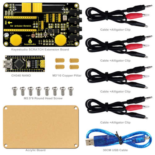
Kit List
Connection Method
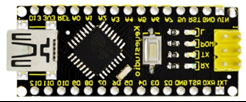
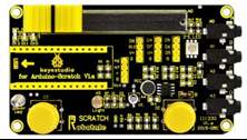
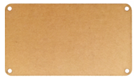
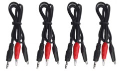
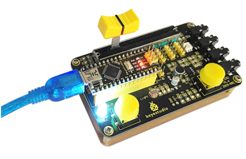
First, plug nano ch340 board into the scratch extension board; Second, mount the whole board on the Acrylic board held by 4 copper bushes, and attach them with 2 screws on two ends of one copper bush; Finally, connect the main board with computer using USB cable. Note: if you need to use analog input, just plug alligator clip and cable into analog input port.
Software Installation
Arduino Introduction
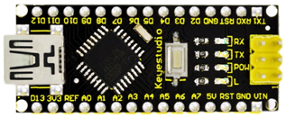
What’s Arduino?
Arduino is an open-source hardware project platform. This platform includes a circuit board with simple I/O function and program development environment software. It can be used to develop interactive products. For example, it can read signals of multiple switches and sensors, and control light, servo motor and other various physical devices. It’s widely applied in robot field.
Install Development Environment Software IDE
The open-source Arduino Software (IDE) makes it easy to write code and upload it to the board. It runs on Windows, Mac OS X, and Linux. The environment is written in Java and based on Processing and other open-source software. This software can be used with any Arduino board. Refer to the page https://www.arduino.cc/en/Guide/HomePage for Installation instructions. Or just look at our instruction. First, download Arduino development software, click below hyperlink: https://www.arduino.cc/en/Main/OldSoftwareReleases#1.5.x Downloaded file is an arduino-1.5.6-r2-windows.zip compressed folder, and unzip it to your hard drive.
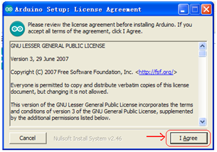
Double click Arduino-1.5.6 .exe. and select “I agree”.
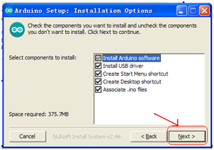
Choose the components to install and click “Next”.
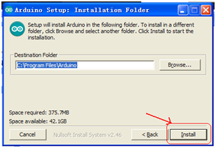
Choose the installation directory (we suggest to keep the default one) and then click “Install”.
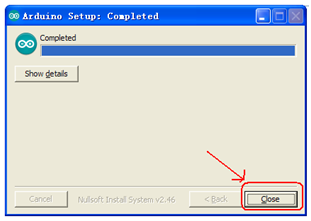
The process will extract and install all the required files to execute properly the Arduino Software (IDE), and click Close.
Below is how Arduino 1.5.6 looks like.
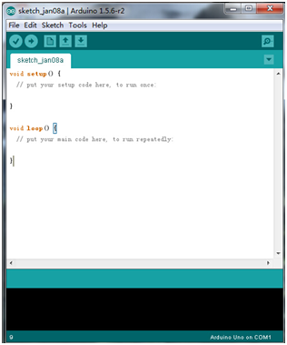
Install Arduino Driver
For different operating system, there may be slight difference in installation method. Next, let’s install Arduino driver for your Arduino board with WIN 7.
When you connect Arduino Uno to your computer the first time, right click “Computer” —> “Properties”—> “Device manager”, you can see “USB2.0-Serial”.
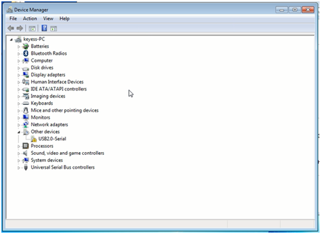
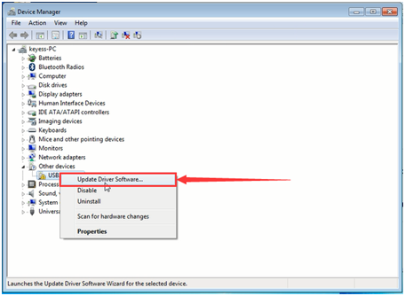
Right click on the "USB2.0-Serial" port and choose the "Update Driver Software" option.
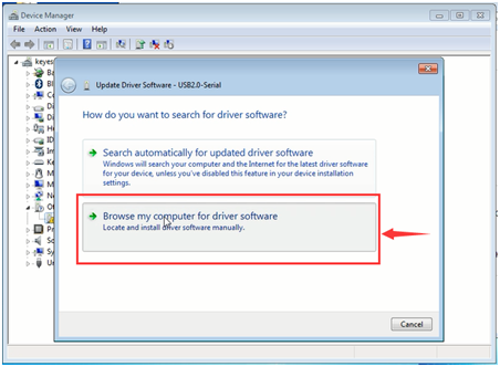
Next, choose the "Browse my computer for Driver software" option.
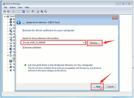
Finally, navigate to and select the Uno's driver file, named "usb_ch341_3.1.2009.06", located in the "Drivers" folder of the Arduino Software download, click “Next”.
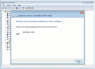
The below dialog boxes automatically appears if you have installed driver successfully and click “Close” to finish.
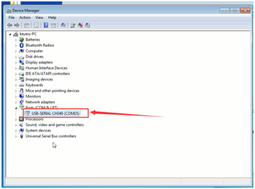
You can check that the drivers have been installed by opening the Windows Device Manager. Go to “Device manager” again. Right click “Computer” → “Properties”→ “Device manager”, you can see CH340 device as below figure shows, also the COM port info.
Introduction to Scratch and S4A Software
Scratch is a simple programming tool aiming at teenagers. Its advantage is: users can be those who even don’t know English, neither keyboard. Commands and parameters of program are displayed by building block module. In order to programming, just drag the blocks to formula bar. Almost all children fall in love with this software at first sight and their desire is aroused to program.
In this kit, we use S4A software as development environment. S4A is a Scratch modification that allows for simple programming of the Arduino open source hardware platform. It provides new blocks for managing sensors and actuators connected to Arduino.
S4A allows for 6 analog inputs (analog pins), 2 digital inputs (digital pins 2 and 3), 3 analog outputs (digital pins 5, 6 and 9), 3 digital outputs (pins 10, 11 and 13) and 4 special outputs. S4A allows you to control as many boards as USB ports you have.
Installing the Firmware into your Arduino
This firmware is a piece of software you need to install into your Arduino board to be able to communicate with it from S4A.
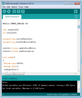
First, Open the firmware file (S4AFirmware15) from the Arduino environment.
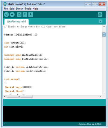
In the Tools menu, select the board version and the serial port where the board is connected.
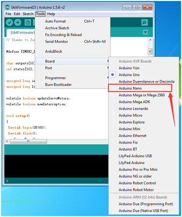
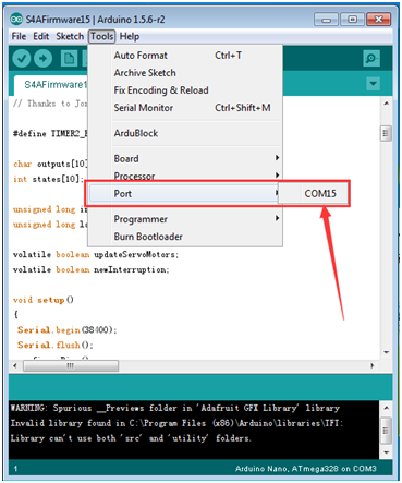
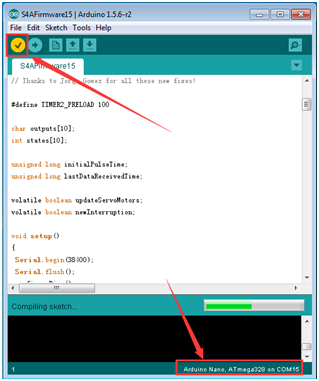
Click Verify ![]()
to check code.
Load the firmware into your board through File > Upload ![]()
.
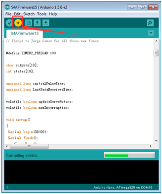
Done uploading as shown below.
Install S4A15 Software
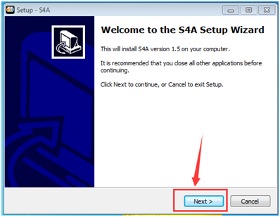
First, double click ![]()
and click Next to continue Setup.
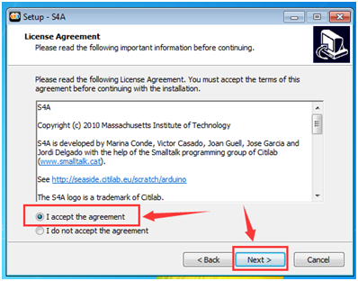
Check I accept the agreement and click Next to continue.
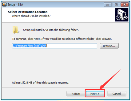
Setup will install S4A into the following folder and to continue, click “Next”.
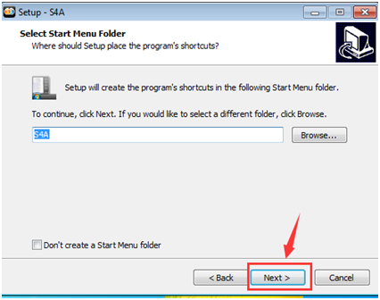
Setup will create the program’s shortcuts in the following Start Menu folder and to continue, click “Next”.
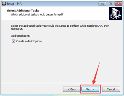
Check Create a desktop icon, and click Next to continue.
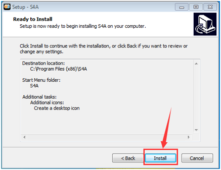
Click Install to install.
Click Finish to exit Setup.
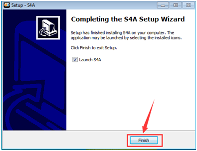
After finishing installing, it enters automatically the following interface.
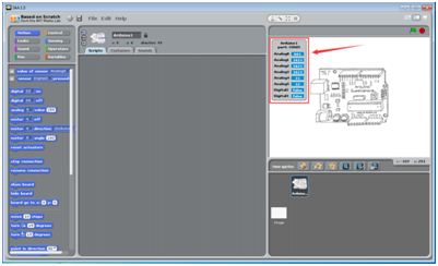
After installing all software needed, it is time to create many interesting projects.
Basic Examples
Here you'll find basic S4A examples, complete with an .sb Scratch project file for you to download in Basic Examples folder.
Project 1: LED Blinking
A simple example showing how to trigger an LED.
Hardware Required:
- Nano ch340*1
- SCRACH*1
- USB Cable*1
Run S4A, click File→Open to open a file Project 1 from Basic Examples folder as shown below.
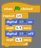
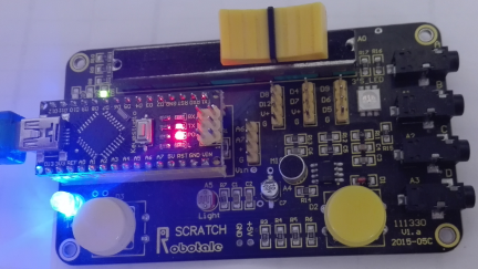
Click the flag ![]() , and the LED on board is on and off for 10s respectively with an interval of 0.5s, repeating 10 times.
, and the LED on board is on and off for 10s respectively with an interval of 0.5s, repeating 10 times.
Project 2: Breathing LED
Make an LED turn on and off gradually.
Hardware Required
- nano ch340*1
- SCRACH*1
- USB Cable*1
Run S4A, click File→Open to open a file Project 2 from Basic Examples folder as shown below.
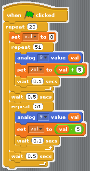
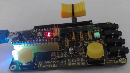
Click the flag ![]() , and RGB on board is on with green and gradually brighten more and then dim off slowly, repeating 20 times.
, and RGB on board is on with green and gradually brighten more and then dim off slowly, repeating 20 times.
Project 3: LED with Chasing Effect
Turn on and off three LED according to a certain sequence and time.
Hardware Required
- nano ch340*1
- SCRACH*1
- USB Cable*1
Run S4A, click File→Open to open a file Project 3 from Basic Examples folder as shown below.
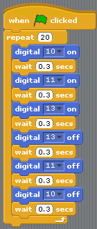
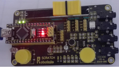
Click the flag ![]() , and the LED on D10, D11and D13 are on and off by sequence, repeating 20 times.
, and the LED on D10, D11and D13 are on and off by sequence, repeating 20 times.
Project 4: Button-controlled LED
An LED that switches state when we push a button.
Hardware Required
- nano ch340*1
- SCRACH*1
- USB Cable*1
Run S4A, click File→Open to open a file Project 4 from Basic Examples folder as shown below.
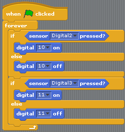
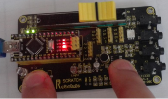
Click the flag ![]() , and touch the button on D2, the LED on D10 is on ; touch the button on D3, the LED on D11is on .
, and touch the button on D2, the LED on D10 is on ; touch the button on D3, the LED on D11is on .
Project 5: Start Moving
A simple project to make a cat start moving.
Hardware Required
- nano ch340*1
- SCRACH*1
- USB Cable*1
Run S4A, click File→Open to open a file Project 5 from Basic Examples folder as shown below.
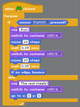
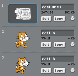
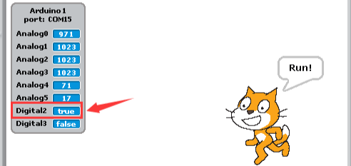
Click the flag ![]() ; the cat stands in the middle, saying “ The rest meets!”; touches the button on D3, and the cat starts moving backward and forward, saying “ Run!”
; the cat stands in the middle, saying “ The rest meets!”; touches the button on D3, and the cat starts moving backward and forward, saying “ Run!”
Project 6: A Light-controlled Walking Cat
Using the input of a photoresistor sensor to walk the cat.
Hardware Required
- nano ch340*1
- SCRACH*1
- USB Cable*1
Run S4A, click File→Open to open a file Project 1 from Basic Examples folder as shown below.
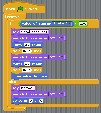
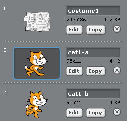
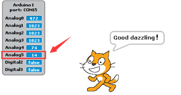
We use photoresistor to detect illumination intensity. The stronger the light to the photoresistor on board , the smaller the analog value A5. Click the flag ; when A5 is greater than 100, the cat stands in the middle, saying “normal!”; when A5 is less than 100, the cat walks backward and forward, saying “Good dazzling!”.
Project 7: A Sound-controlled Walking Cat
Using an on-board microphone to walk a cat.
Hardware Required
- nano ch340*1
- SCRACH*1
- USB Cable*1
Run S4A, click File→Open to open a file Project 7 from Basic Examples folder as shown below.
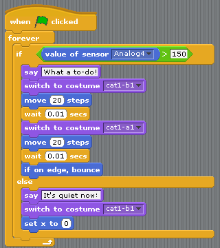
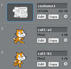
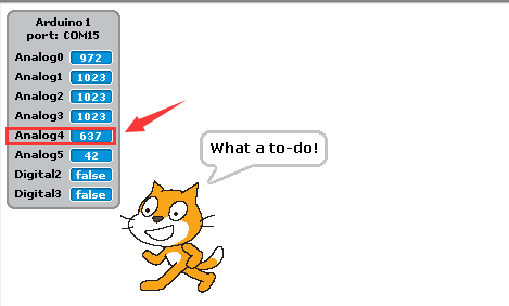
We use an on-board microphone to detect sound intensity. The stronger the sound to the microphone on board , the larger the analog value A4. Click the flag ![]() ; when A4 is less than 150, the cat stands in the middle, saying “It's quiet now!”; when A4 is greater than 150, the cat walks backward and forward, saying ““What a to-do!””.
; when A4 is less than 150, the cat stands in the middle, saying “It's quiet now!”; when A4 is greater than 150, the cat walks backward and forward, saying ““What a to-do!””.
Project 8: A Sound-controlled LED
Using an on-board microphone to trigger a LED.
Hardware Required
- nano ch340*1
- SCRACH*1
- USB Cable*1
Run S4A, click File→Open to open a file Project 8 from Basic Examples folder as shown below.
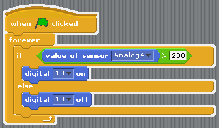
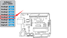
We use an on-board microphone to detect sound intensity. Click the flag ![]() , when A4 is greater than 200, D10 LED is on.
, when A4 is greater than 200, D10 LED is on.
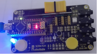
Project 9: A Light-controlled LED
Using an on-board photoresistor to trigger a LED.
Hardware Required
- nano ch340*1
- SCRACH*1
- USB Cable*1
Run S4A, click File→Open to open a file Project 9 from Basic Examples folder as shown below.
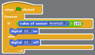
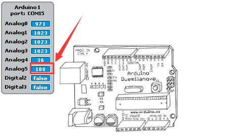
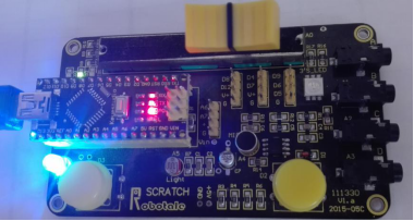
We use photoresistor to detect illumination intensity. The stronger the light to the photoresistor on board, the smaller the analog value A5. Click the flag ![]() ; when A5 is greater than 100, the D11 LED is turned on.
; when A5 is greater than 100, the D11 LED is turned on.
Project 10: Rolling a Ball with Slider
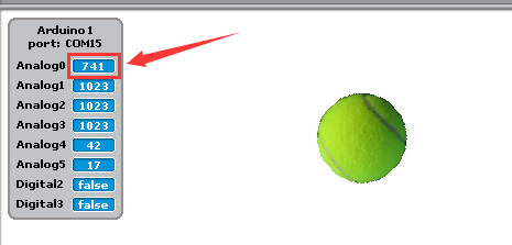
Using an on-board potentiometer to adjust position and revolving speed of a ball.
Hardware Required
- nano ch340*1
- SCRACH*1
- USB Cable*1
Run S4A, click File→Open to open a file Project 10 from Basic Examples folder as shown below.
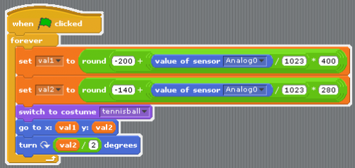
Move the on-board slider to get a analog value; position and revolving speed of the ball changes with value; when the ball moves to the upside or bottom corner, it rolls at the fastest speed; when it moving in the middle, it rolls at the slowest speed.
Resources
Video
http://video.keyestudio.com/KS0189/
https://drive.google.com/open?id=1iHhvHIgC2g28jc5gLJShe34RN3LWzzV_
Driver Software
https://drive.google.com/open?id=1edkU6sX4x7lyF1AIEymZ5kU2Jfx43VFN
S4A15 Software (Windows)
http://s4a.cat/downloads/S4A15.exe
S4A Firmware
https://drive.google.com/open?id=1lXhm2CMCeWwWIGTDQgkISRCajEKa8bVz
Basic Examples
https://drive.google.com/open?id=13ZitQ7D2XzTeYJJtki7b-kn7YYPVtBfB
Buy from
Official Website
http://www.keyestudio.com/keyestudio-maker-touch-shield.html
