Ks0354 Keyestudio ESP8266 WI-FI Development Board: Difference between revisions
Keyestudio (talk | contribs) No edit summary |
Keyestudio (talk | contribs) |
||
| Line 79: | Line 79: | ||
<br>[[Image:ks0354 driver 1.png|600px|frameless]]<br> | <br>[[Image:ks0354 driver 1.png|600px|frameless]]<br> | ||
Then right-click on the device and select the top menu option (Update Driver Software...) shown as the figure below | Then right-click on the device and select the top menu option (Update Driver Software...) shown as the figure below. | ||
<br>[[Image:ks0354 driver 2.png|600px|frameless]]<br> | <br>[[Image:ks0354 driver 2.png|600px|frameless]]<br> | ||
| Line 95: | Line 95: | ||
<br> | <br> | ||
===Step3| Installing the ESP8266 with Arduino=== | ===Step3| Installing the ESP8266 with Arduino=== | ||
Double-click the icon of Arduino software downloaded well, you will get the interface shown below. | Double-click the icon of Arduino software downloaded well, you will get the interface shown below. | ||
Revision as of 13:05, 26 December 2018
Description
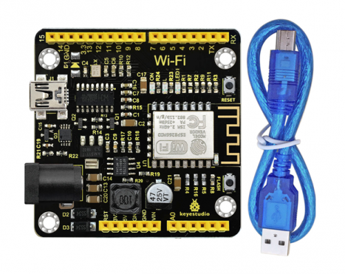
This keyestudio ESP8266 WI-FI development board is based on the ESP8266-12FWIFI module developed by Ai-Thinker.
The processor ESP8266 integrates the industry-leading Tensilica L106 ultra-low-power 32-bit micro MCU in a smaller package, with 16-bit Lite mode.
The main frequency supports 80MHz and 160 MHz.
It supports RTOS, integrated with Wi-Fi MAC/BB/RF/PA/LNA. Onboard comes with curved antenna.
This development board is a standalone network controller, which can add networking function to those existing devices.
It has 11 I/O ports (4 of which can be used as PWM output), and all I/O ports operate at 3.3V. It also comes with an AD input interface, supporting the voltage range of 0-3.3V.
The board can be powered via the USB port, or with an external power supply (DC 7-12V), or powered by the female headers Vin/GND (DC 7-12V).
Technical Details
- Microcontroller: ESP8266-12F
- Operating Voltage: 3V3
- Input Voltage (recommended): DC 7-12V
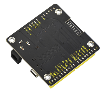
- Digital I/O Pins: 8 (GPIO2, GPIO4, GPIO5, GPIO12, GPIO13, GPIO14, GPIO15, GPIO16)
- Analog Input Pins: 1 (A0)
- IO output maximum current: 12 mA
- Main frequency supports 80 MHz and 160 MHz
- LED_BUILTIN: GPIO 14
- Comes with an external power jack (DC 7-12V)
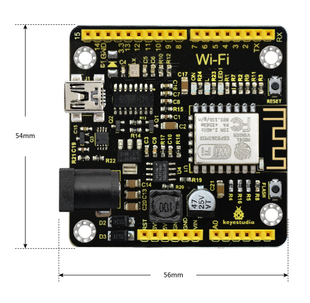
- Dimensions: 54mm*56mm*15mm
Element and Interfaces
Here is an explanation of what every element and interface of the board does:
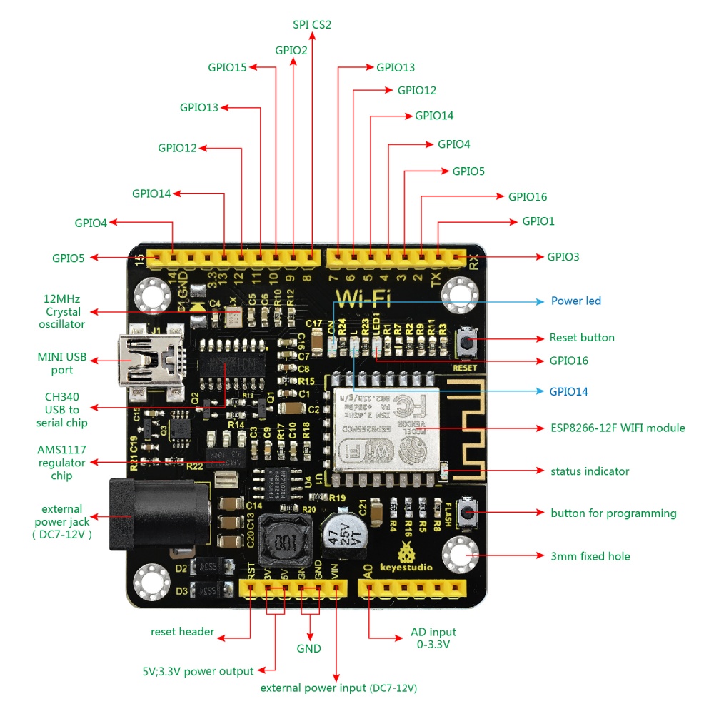
Specialized Functions of Some Pins
- Serial communication: ' GPIO3 (RX) and GPIO1 (TX).
- PWM Interfaces (Pulse-Width Modulation): GPIO 4, GPIO 12, GPIO 14, GPIO 15.
- SPI communication: GPIO6(CLK), GPIO7(MISO), GPIO8(MOSI), GPIO9 (HD), GPIO10(WP), GPIO1(CS1), GPIO0(CS2)
- IIC communication: GPIO2(SDA); GPIO14(SCL)
- IR Remote Control Interface: GPIO5(IR RX); GPIO14(IR TX)
Detailed Using Methods are as follows:
Step1| Install the Arduino IDE
When programming the control board, first you should install the Arduinosoftware and driver.
You can download the different versions for different systems from the link below:
https://www.arduino.cc/en/Main/OldSoftwareReleases#1.5.x
NOTE: this control board is only compatible with Arduino 1.6.5 version or latest.
In the following, we will download the Arduino 1.6.5 version.
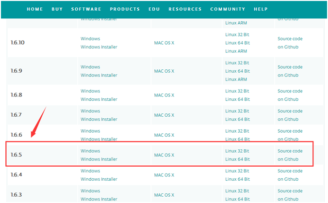
In this Windows system page, there are two options. One is Windows version, the other is Windows Installer.
For Windows Installer, you can download the installation file, this way you need to install the arduino IDE.

For simple Windows version, you can download the software directly, do not need to install, just directly use the software after unzip the file.

Next, we click the Windows, pop up the interface as below.
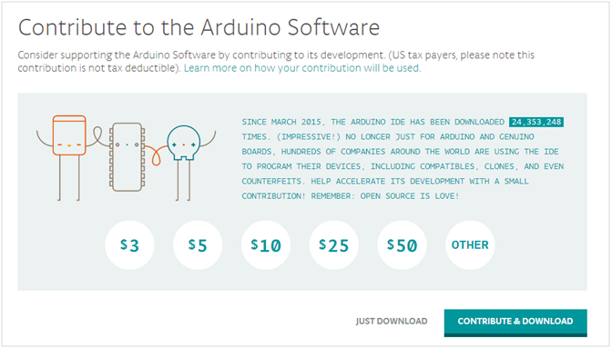
Click JUST DOWNLOAD.When the ZIP file is downloaded well to your computer, you can directly unzip the file. Open the Arduino-1.6.5-r5 folder, you should get it as follows.
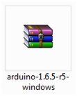
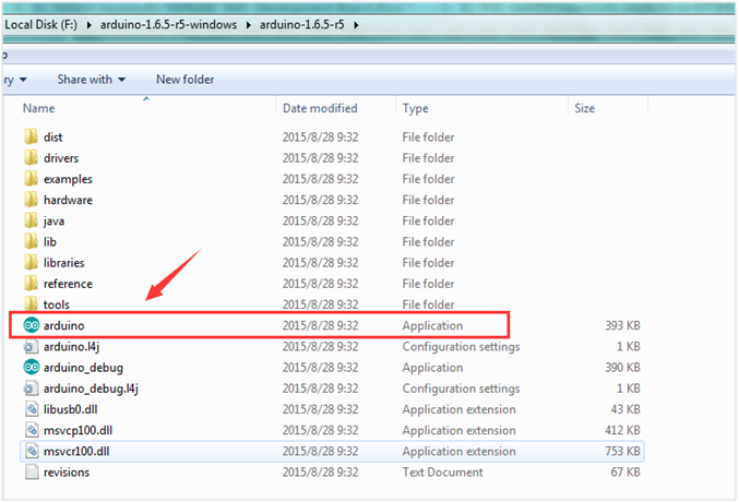
Click the icon of ARDUINO software to open it. This is your Arduino.
Step2| Installing the Driver
The USB to serial port chip of this control board is CH340G. So you need to install the driver for the chip. You can click the driver file here usb_ch341_3.1.2009.06 to download it.
In different systems, the driver installation is similar. Here we start to install the driver on the Win7 system.
Plug one end of your USB cable into the Keyestudio ESP8266 WI-FI board and the other into a USB socket on your computer.
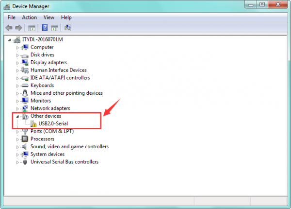
When you connect the ESP8266 WI-FI board to your computer at the first time, right click your “Computer” —>for “Properties”—> click the “Device manager”, under Other devices, you should see the “USB2.0-Serial”.
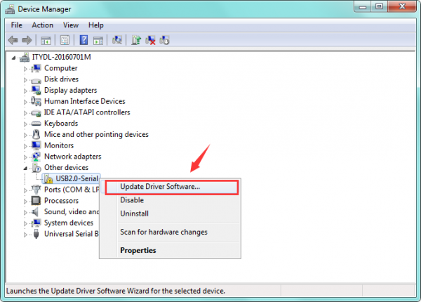
Then right-click on the device and select the top menu option (Update Driver Software...) shown as the figure below.
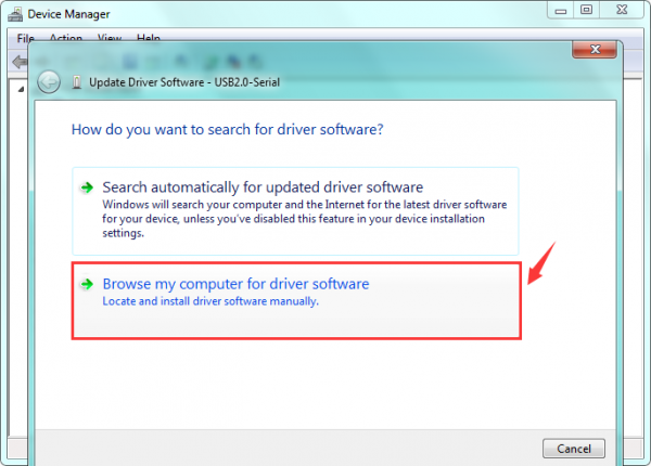
Then it will be prompted to either “Search Automatically forupdated driversoftware” or “Browse my computer for driver software”. Shown as below. In this page, select “Browse my computer for driver software”.
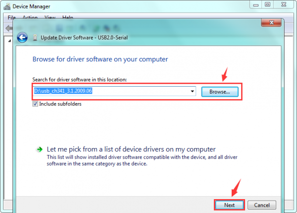
After that, select the option to browseand navigate to the “drivers” folder of usb-ch341 installation.
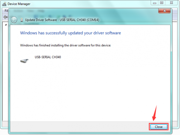
Once the software has been installed, you will get a confirmation message. Installation completed, click “Close”.
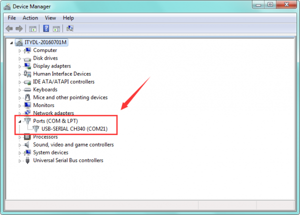
Up to now, the driver is installed well. Then you can right click “Computer” —>“Properties”—>“Device manager”, you should see the device as the figure shown below.
Step3| Installing the ESP8266 with Arduino
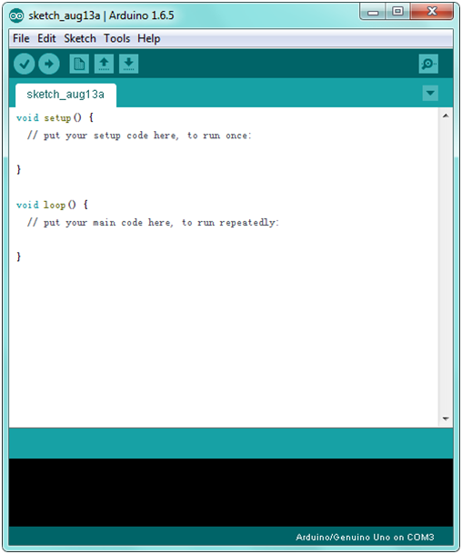
Double-click the icon of Arduino software downloaded well, you will get the interface shown below.
(Note: if the Arduino software loads in the wrong language, you can change it in the preferences dialog. See the environment page for details.)

The functions of each button on the Toolbar are listed below:
![]()
First, plug one end of your USB cable into the Keyestudio ESP8266 WI-FI board and the other into a USB socket on your computer.
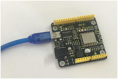
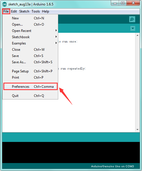
Then open the Arduino IDE, click the “File” to select the “Preferences”.
The pop-up interface is shown below.
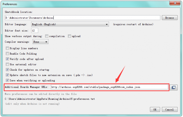
See the “Additional Boards Manager URLs”, copy and paste the link:
http://arduino.esp8266.com/stable/package_esp8266com_index.json and then click OK.
After that, click “Tools”, for “Board”, enter theBoards Manager, it will automatically download the relevant file. Shown below.
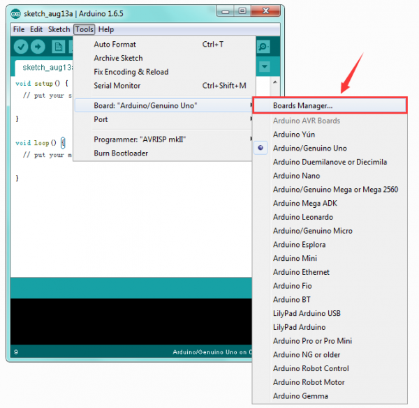
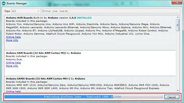
Done downloading the relevant file, it will pop up the window below. Then enter the 8266 on the blank bar and click Install.
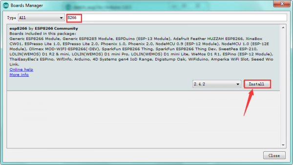
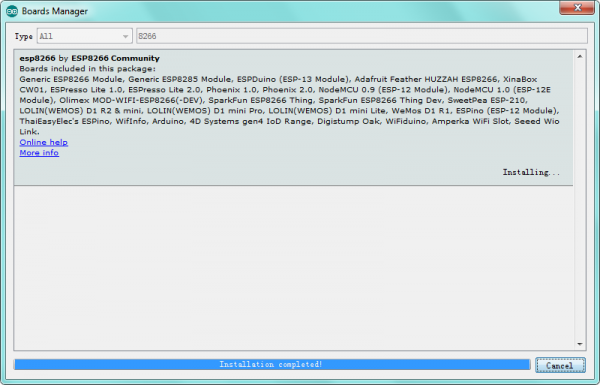
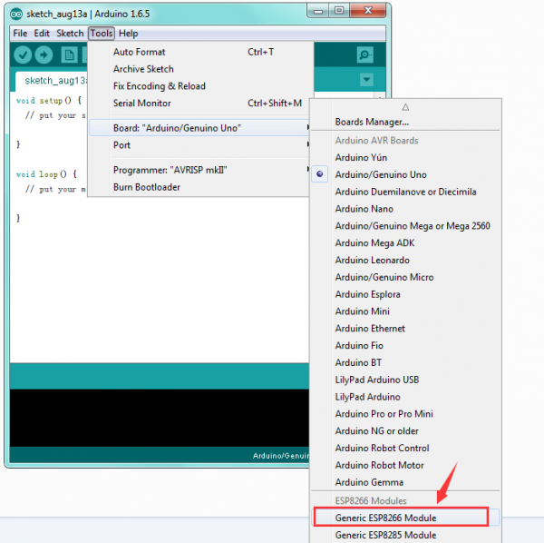
Installation completed, click Close, then click “Tools”, for “Board”, you should see the Generic ESP8266 Module. Shown below.
Step4| Add the Libraries
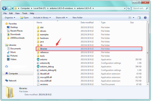
Before upload the code to test your board, you should first add all the libraries into the libraries folder of Arduino-1.6.5-r5. You can click the link to download all the libraries needed.
https://drive.google.com/open?id=11mTs_DbCIx-PQHPjfZOAekBZ7IL8al3D
Step5| Select the Board and Serial Port
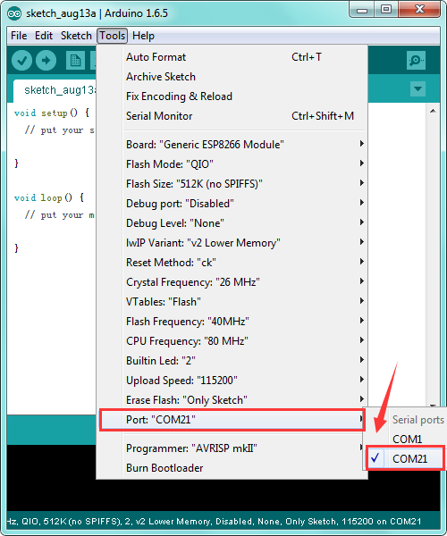
Open the Arduino IDE, you’ll need to click the “Tools”, then select the Board and the Serial Port.

You can check the Serial Port on your computer’s Device Manager.

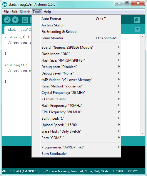
Below is the complete settings you should refer to:
Step6| Upload the Code
Add well all the libraries mentioned above, and select well the Board and Port, you should upload the code to test your board.
Below is an example code, you can copy and paste it on Arduino IDE. Or dowload the code here
Pay attention to:
If you fail to upload the code, you should firstly press the RESET button ![]() , then long press down the FLASH button until the code upload successfully, finally release the button.
, then long press down the FLASH button until the code upload successfully, finally release the button.
NOTE: in the code, you should modify the WIFI name and password here:
const char* WIFI_SSID = "HUAWEI-3L9ML8";
const char* WIFI_PWD = "75785302";
#include <ESP8266WiFi.h>
#include <WiFiUdp.h>
#include <Ticker.h>
#include <JsonListener.h>
#include "SSD1306Wire.h"
#include "OLEDDisplayUi.h"
#include "Wire.h"
#include "WorldClockClient.h"
#include "icons.h"
#include "fonts.h"
#define SDA_PIN 5//oled_SDA
#define SCL_PIN 4//oled_SCL


/***************************
 * Begin Settings
 **************************/
// WIFI
const char* WIFI_SSID = "HUAWEI-3L9ML8";
const char* WIFI_PWD = "75785302";

// Setup
const int UPDATE_INTERVAL_SECS = 10 * 60; // Update every 10 minutes

// Display Settings
const int I2C_DISPLAY_ADDRESS = 0x3c;

// TimeClient settings


// Initialize the oled display for address 0x3c
// sda-pin=14 and sdc-pin=12

SSD1306Wire  display(I2C_DISPLAY_ADDRESS, SDA_PIN, SCL_PIN);
OLEDDisplayUi ui     ( &display );

/***************************
 * End Settings
 **************************/
String timeZoneIds [] = {"America/New_York", "Europe/London", "Europe/Paris", "Australia/Sydney"};
WorldClockClient worldClockClient("de", "CH", "E, dd. MMMMM yyyy", 4, timeZoneIds);


// flag changed in the ticker function every 10 minutes
bool readyForUpdate = false;

String lastUpdate = "--";

Ticker ticker;


void updateData(OLEDDisplay *display) {
  drawProgress(display, 50, "Updating Time...");
  worldClockClient.updateTime();
  drawProgress(display, 100, "Done...");
  readyForUpdate = false;
  delay(1000);
}

void drawProgress(OLEDDisplay *display, int percentage, String label) {
  display->clear();
  display->setTextAlignment(TEXT_ALIGN_CENTER);
  display->setFont(ArialMT_Plain_10);
  display->drawString(64, 10, label);
  display->drawProgressBar(10, 28, 108, 12, percentage);
  display->display();
}

void drawClock(OLEDDisplay *display, int x, int y, int timeZoneIndex, String city, const char* icon) {
  display->setTextAlignment(TEXT_ALIGN_LEFT);
  display->setFont(ArialMT_Plain_10);
  display->drawString(x + 60, y + 5, city);
  display->setFont(Crushed_Plain_36);
  display->drawXbm(x, y, 60, 60, icon);
  display->drawString(x + 60, y + 15, worldClockClient.getHours(timeZoneIndex) + ":" + worldClockClient.getMinutes(timeZoneIndex));

}

void drawFrame1(OLEDDisplay *display, OLEDDisplayUiState* state, int16_t x, int16_t y) {
  drawClock(display, x, y, 0, "New York",  new_york_bits);
}

void drawFrame2(OLEDDisplay *display, OLEDDisplayUiState* state, int16_t x, int16_t y) {
  drawClock(display, x, y, 1, "London",  london_bits);
}

void drawFrame3(OLEDDisplay *display, OLEDDisplayUiState* state, int16_t x, int16_t y) {
  drawClock(display, x, y, 2, "Paris",  paris_bits);
}

void drawFrame4(OLEDDisplay *display, OLEDDisplayUiState* state, int16_t x, int16_t y) {
  drawClock(display, x, y, 3, "Sydney",  sydney_bits);
}


void setReadyForWeatherUpdate() {
  Serial.println("Setting readyForUpdate to true");
  readyForUpdate = true;
}

// this array keeps function pointers to all frames
// frames are the single views that slide from right to left
FrameCallback frames[] = { drawFrame1, drawFrame2, drawFrame3, drawFrame4};
int numberOfFrames = 4;

void setup() {
  Serial.begin(115200);
  Serial.println();
  Serial.println();

  // initialize dispaly
  display.init();
  display.clear();
  display.display();

  //display.flipScreenVertically();
  display.setFont(ArialMT_Plain_10);
  display.setTextAlignment(TEXT_ALIGN_CENTER);
  display.setContrast(255);

  WiFi.begin(WIFI_SSID, WIFI_PWD);

  int counter = 0;
  while (WiFi.status() != WL_CONNECTED) {
    delay(500);
    Serial.print(".");
    display.clear();
    display.drawString(64, 10, "Connecting to WiFi");
    display.drawXbm(46, 30, 8, 8, counter % 3 == 0 ? activeSymbol : inactiveSymbol);
    display.drawXbm(60, 30, 8, 8, counter % 3 == 1 ? activeSymbol : inactiveSymbol);
    display.drawXbm(74, 30, 8, 8, counter % 3 == 2 ? activeSymbol : inactiveSymbol);
    display.display();

    counter++;
  }

  ui.setTargetFPS(30);

  // You can change this to
  // TOP, LEFT, BOTTOM, RIGHT
  ui.setIndicatorPosition(BOTTOM);

  // Defines where the first frame is located in the bar.
  ui.setIndicatorDirection(LEFT_RIGHT);

  // You can change the transition that is used
  // SLIDE_LEFT, SLIDE_RIGHT, SLIDE_TOP, SLIDE_DOWN
  ui.setFrameAnimation(SLIDE_LEFT);

  // Add frames
  ui.setFrames(frames, numberOfFrames);

  // Inital UI takes care of initalising the display too.
  ui.init();

  Serial.println("");

  updateData(&display);

  ticker.attach(UPDATE_INTERVAL_SECS, setReadyForWeatherUpdate);

}

void loop() {

  if (readyForUpdate && ui.getUiState()->frameState == FIXED) {
    updateData(&display);
  }

  int remainingTimeBudget = ui.update();

  if (remainingTimeBudget > 0) {
    // You can do some work here
    // Don't do stuff if you are below your
    // time budget.
    delay(remainingTimeBudget);
  }
}
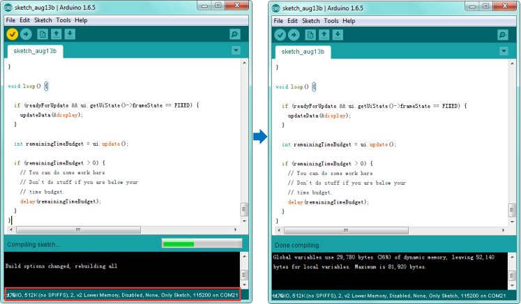
After copy and paste the code on IDE, click the compile button, if compiling successfully, the message "Done compiling." will appear in the status bar. Shown below.
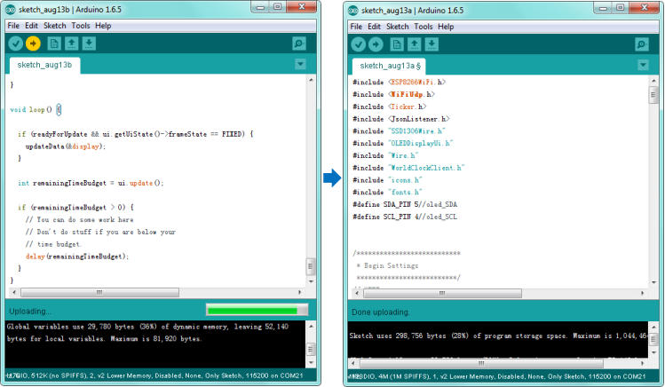
Then click the “Upload” button, if the upload is successful, the message "Done uploading." will appear in the status bar.
Step7| What Should You See
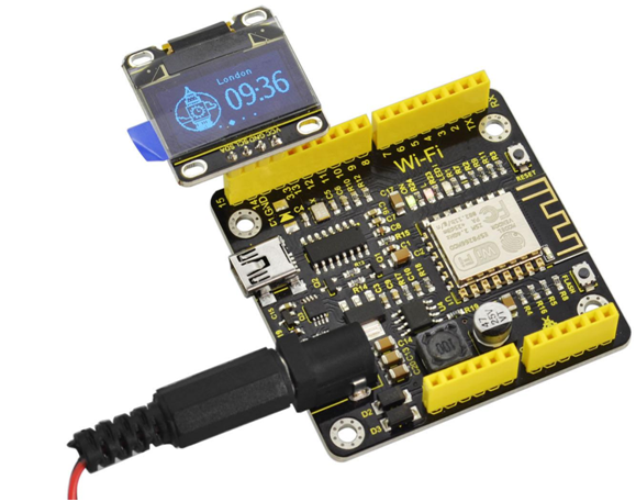
Done uploading, connect the keyestudio OLED display module to the WIFI board (separately GPIO5, GPIO4, GND, 3.3V), then supply the control board with DC 7-12V power via a black external DC jack.
Finally, the board will be connected to the WIFI you have set in the code, so you should see the worldwide time display.
Package List
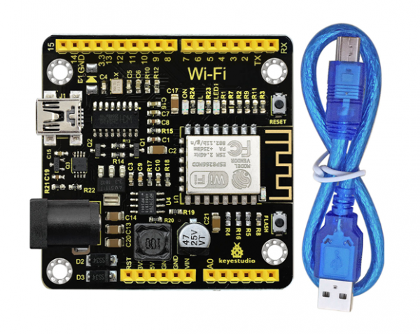
- Keyestudio ESP8266 WI-FI Development Board * 1
- USB cable * 1
More Resources
You can download the PDF file from the link:
https://drive.google.com/open?id=1jEDfJttzF6Rto5Qg96Q2kK_dEKz09n3e
Driver File Download:
https://drive.google.com/open?id=1ssALY3RCks_VnWJJ-TuBczs28s2gimEI
Download the Libraries:
https://drive.google.com/open?id=11mTs_DbCIx-PQHPjfZOAekBZ7IL8al3D
Download the Source Code:
https://drive.google.com/open?id=1bYBkZpkznGzVIrcFOBszWwVbIONHVwJw
ARDUINO Software:
https://www.arduino.cc/en/Main/OldSoftwareReleases#1.5.x
Buy From
- official website: http://www.keyestudio.com/ks0354.html
