KS0396 keyestudio 8x8 LED Matrix Module Address Select: Difference between revisions
Keyestudio (talk | contribs) (Created page with " thumb|500px|right|EASY plug 8x8 LED Matrix Module Address Select(Black and Eco-friendly) ==Introduction== What's better than a single LED? Lots of L...") |
Keyestudio (talk | contribs) No edit summary |
||
| Line 1: | Line 1: | ||
[[image: | [[image:0396图片1.png|thumb|500px|right|keyestudio 8x8 LED Matrix Module Address Select(Black and Eco-friendly)]] | ||
==Introduction== | ==Introduction== | ||
| Line 23: | Line 23: | ||
<br> | <br> | ||
==Hookup Guide== | ==Hookup Guide== | ||
<br>[[File: | <br>[[File:0396图片2.png|600px|frameless|thumb]]<br> | ||
<br> | <br> | ||
| Line 62: | Line 62: | ||
==Test Result== | ==Test Result== | ||
Done uploading the code to the board, power on, you should see the 8*8 matrix displaying a heart image. Shown below. | Done uploading the code to the board, power on, you should see the 8*8 matrix displaying a heart image. Shown below. | ||
<br>[[File: | <br>[[File:0396图片6.png|600px|frameless|thumb]]<br> | ||
<br> | <br> | ||
| Line 68: | Line 68: | ||
'''1.Set the communication address.''' Refer to the address chart. <br> | '''1.Set the communication address.''' Refer to the address chart. <br> | ||
The code is set as below. | The code is set as below. | ||
<br>[[File:0395图片4.png|600px|frameless|thumb]] [[File: | <br>[[File:0395图片4.png|600px|frameless|thumb]] [[File:0396图片3.png|600px|frameless|thumb]]<br> | ||
<br>[[File:0395图片6.png|600px|frameless|thumb]]<br> | <br>[[File:0395图片6.png|600px|frameless|thumb]]<br> | ||
| Line 77: | Line 77: | ||
<br> | <br> | ||
Place the matrix module as follows: | Place the matrix module as follows: | ||
<br>[[File: | <br>[[File:0396图片4.png|600px|frameless|thumb]]<br> | ||
<br> | <br> | ||
Then convert 0x00,0x18,0x24,0x42,0x81,0x99,0x66,0x00 into Binary number:<br> | Then convert 0x00,0x18,0x24,0x42,0x81,0x99,0x66,0x00 into Binary number:<br> | ||
| Line 101: | Line 101: | ||
==Extension Experiment== | ==Extension Experiment== | ||
You can connect several modules to the shield, then connect them to control board, and change the communication address, controlling the matrix modules display different images. | You can connect several modules to the shield, then connect them to control board, and change the communication address, controlling the matrix modules display different images. | ||
<br>[[File: | <br>[[File:0396图片5.png|600px|frameless|thumb]]<br> | ||
<br> | <br> | ||
Revision as of 16:14, 2 January 2019
Introduction
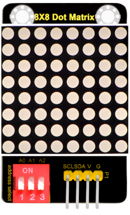
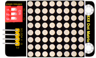
What's better than a single LED? Lots of LEDs! A fun way to make a small display is to use an 8x8 matrix.
This module uses HT16K33 chip to drive an 8x8 dot matrix.
Just need to use the I2C communication port of microcontroller to control the dot matrix, which can save more port resources of microcontroller.
The matrix module comes with a 4Pin header of 2.54mm pin pitch.
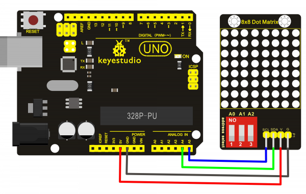
You can connect the module to control board for communication using jumper wires.
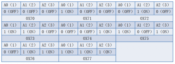
Besides, it comes with three DIP switches. You can randomly toggle the switch to select the I2C communication address.
The address settings are as shown below.
Technical Details
- Interface: 4Pin header
- Operating voltage: DC 4.5V-5.5V
- Comes with three DIP switches for address selection
- Dimensions:52mm*34mm*11mm
- Weight:13.2g
Hookup Guide
Test Code
- Download the library:
https://drive.google.com/open?id=1cg90JqypbThqqhquhMEVZLq2CLzeYkrd
#include <Matrix.h>
Matrix myMatrix(A4,A5);
uint8_t LedArray1[8]={0x00,0x18,0x24,0x42,0x81,0x99,0x66,0x00};
uint8_t  LEDArray[8];
void setup(){
myMatrix.begin(0x70);
}

void loop(){
  myMatrix.clear();
  for(int i=0; i<8; i++)
  {
    LEDArray[i]=LedArray1[i];
    for(int j=7; j>=0; j--)
    {
      if((LEDArray[i]&0x01)>0)
      myMatrix.drawPixel(j, i,1);
      LEDArray[i] = LEDArray[i]>>1;
    }
  }
  myMatrix.writeDisplay();
}
Note: before compiling the code, do remember to place the Matrix library folder into directory \Arduino\libraries. Otherwise, fail to compile the code.
For example: C:\Program Files\Arduino\libraries
Test Result
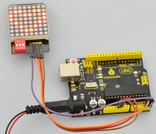
Done uploading the code to the board, power on, you should see the 8*8 matrix displaying a heart image. Shown below.
Settings Method
1.Set the communication address. Refer to the address chart.
The code is set as below.


2.Set the display image
You can set the display image in the code shown below.
![]()
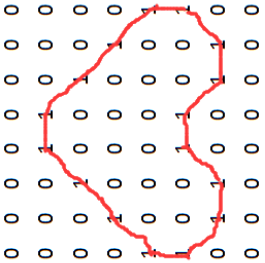
Place the matrix module as follows:
Then convert 0x00,0x18,0x24,0x42,0x81,0x99,0x66,0x00 into Binary number:
- 0x00 should be 0 0 0 0 0 0 0 0
- 0x18 should be 0 0 0 1 1 0 0 0
- 0x24 should be 0 0 1 0 0 1 0 0
- 0x42 should be 0 1 0 0 0 0 1 0
- 0x81 should be 1 0 0 0 0 0 0 1
- 0x99 should be 1 0 0 1 1 0 0 1
- 0x66 should be 0 1 1 0 0 1 1 0
- 0x00 should be 0 0 0 0 0 0 0 0
The first hexadecimal number represents the control of the first column of LEDs. The second data represents the control of the second column of LEDs. And so on.
The settings is converting Hexadecimal data into binary data 8-bit.
The number 0 means LED off, and number 1 means LED on.
The first converted number is controlling the first row of LED on and off, and so on.
Extension Experiment
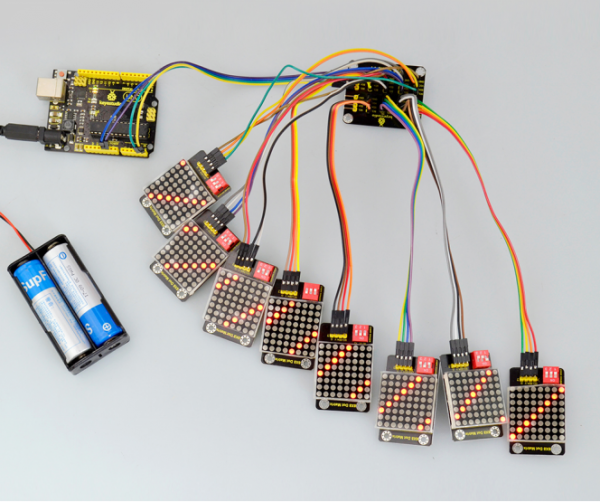
You can connect several modules to the shield, then connect them to control board, and change the communication address, controlling the matrix modules display different images.
Resources Download
- Download all the information:
https://drive.google.com/open?id=1Q1uxj7ZMq_N58vhqAydvx4BgsiJegJPO
- Download the datasheet:
https://drive.google.com/open?id=1aiuKBF6iqwjcavzT8Dbxie3jyT_hKT-q
Get One Now
- Official website: http://www.keyestudio.com/ks0396.html
