Ks0109 keyestudio EASY plug Analog Rotation Sensor: Difference between revisions
Keyestudio (talk | contribs) |
Keyestudio (talk | contribs) |
||
| Line 7: | Line 7: | ||
<span style=color:red> '''Special Note:''' <br> | <span style=color:red> '''Special Note:''' <br> | ||
The sensor/module is | The sensor/module is equipped with the RJ11 6P6C interface, compatible with our keyestudio EASY plug Control Board with RJ11 6P6C interface. <br> If you have the control board of other brands, it is also equipped with the RJ11 6P6C interface but has different internal line sequence, can’t be used compatibly with our sensor/module. </span><br> | ||
<br> | <br> | ||
Revision as of 09:34, 22 May 2019
Introduction
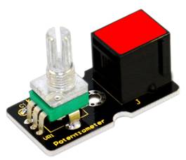
The sensor is based on a potentiometer. A potentiometer is also known as a variable resistor. It is a perfect demonstration of a variable voltage divider circuit. Its voltage can be subdivided into 1023, easy to be connected to Arduino with our sensor shield.
Combined with other sensors, you are able to make interesting projects by reading the analog value from the IO port.
This module should be used together with EASY plug control board.
Special Note:
The sensor/module is equipped with the RJ11 6P6C interface, compatible with our keyestudio EASY plug Control Board with RJ11 6P6C interface.
If you have the control board of other brands, it is also equipped with the RJ11 6P6C interface but has different internal line sequence, can’t be used compatibly with our sensor/module.
Specification
- Connector: Easy plug
- Supply Voltage: 3.3V to 5V
- Sensor type: Analog
Technical Details
- Dimensions: 39mm*20mm*29mm
- Weight: 9.1g
Connect It Up
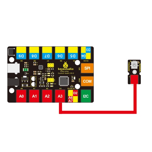
Connect the EASY Plug potentiometer sensor to control board using an RJ11 cable. Then connect the control board to your PC with a USB cable.
Upload the Code
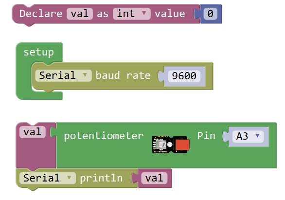
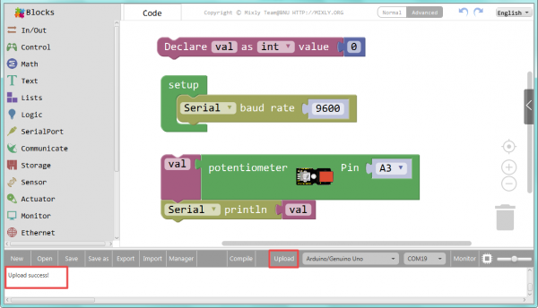
Below is an example code. Open or drag below code to Mixly Blocks and upload.
What You Should See
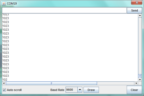
After uploading the code, open the serial monitor and set the baud rate to 9600, you should see the analog value is showed on the monitor.
If rotate the potentiometer, the printed analog value will change within the range of 0-1023.
Extension Experiment
Controlling Light Brightness
Complete the above experiment, want to try a different experiment?
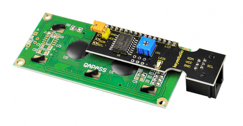
Next, you will learn how to display the potentiometer value on the 1602 LCD screen and to control the brightness of LED using a potentiometer sensor.
Let’s get started right now!
Hookup Guide
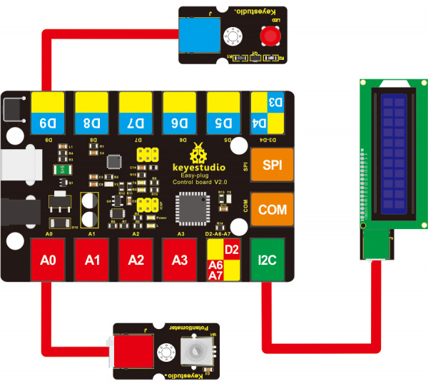
Connect the EASY Plug potentiometer sensor, a red LED module and 1602 LCD module to control board using RJ11 cables.
Test Code
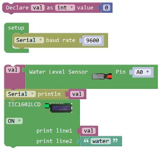
Below is an example code.
What You Should See
After uploading the code, rotate the potentiometer knob, you can see the converted value by potentiometer within 0~255 on the 1602 LCD screen, controlling the brightness of LED module.
Little Knowledge:
- Remember you can adjust the contrast by rotating a blue potentiometer on the LCD back if you can’t make out the words clearly.
Resources
Download the Arduino Code and PDF:
https://drive.google.com/open?id=1m2icC6OGiJoR2O6QFtjyb1Vh-pch2LY2
Download the Mixly Code and PDF:
https://drive.google.com/open?id=1VWbcsg-iEsRl12appSSCdEWLgzHSohVo
