Ks0121 keyestudio EASY plug Photo Interrupter Module: Difference between revisions
Keyestudio (talk | contribs) |
Keyestudio (talk | contribs) |
||
| (5 intermediate revisions by the same user not shown) | |||
| Line 6: | Line 6: | ||
By emitting a beam of infrared light from one end to another end, the sensor can detect an object when it passes through the beam. <br> | By emitting a beam of infrared light from one end to another end, the sensor can detect an object when it passes through the beam. <br> | ||
Useful for many applications such as optical limit switches, pellet dispensing, general object detection, etc.<br> | Useful for many applications such as optical limit switches, pellet dispensing, general object detection, etc.<br> | ||
<span style= | This module needs to be used together with EASY plug control board.<br> | ||
<span style=color:red> '''Special Note:''' <br> | |||
The sensor/module is equipped with the RJ11 6P6C interface, compatible with our keyestudio EASY plug Control Board with RJ11 6P6C interface. <br> If you have the control board of other brands, it is also equipped with the RJ11 6P6C interface but has different internal line sequence, can’t be used compatibly with our sensor/module. </span><br> | |||
<br> | <br> | ||
| Line 21: | Line 26: | ||
==Connect It Up == | ==Connect It Up == | ||
Connect the EASY Plug | Connect the EASY Plug Photo Interrupter module and LED module to control board using RJ11 cables. Then connect the control board to your PC with a USB cable. | ||
<br>[[File: | <br>[[File:光折断灯.jpg|600px|frameless|thumb]]<br> | ||
<br> | |||
==Upload the Code== | ==Upload the Code== | ||
Below is an example code. Open or drag below code to [https://wiki.keyestudio.com/Getting_Started_with_Mixly Mixly Blocks] and upload. <br> | |||
< | <br>[[File:ks0397 10.1.png|600px|frameless|thumb]]<br> | ||
< | |||
<br> | <br> | ||
==What You Should See== | ==What You Should See== | ||
Done uploading the code, powered on, if pick up a piece of paper | Done uploading the code, powered on, if pick up a piece of paper to cover the light on the groove part of module, you should see the LED is turned on. If no interruption, the LED is off. <br> | ||
<br>[[File: | <br>[[File:ks0397 10-1.png|600px|frameless|thumb]]<br> | ||
<br>[[File:ks0397 10-2.png|600px|frameless|thumb]]<br> | |||
<br> | |||
==Extension Experiment== | |||
<span style=color:red><big>'''Adding 4-digit LED Display'''</big></span><br> | |||
<br> | |||
'''Hookup Guide'''<br> | |||
Connect the EASY Plug crash sensor, 4-digit LED display and LED module to control board using RJ11 cables. <br> | |||
<br>[[File:光折断数码管灯.jpg|600px|frameless|thumb]]<br> | |||
<br> | |||
'''Upload the Code'''<br> | |||
Below is an example code.<br> | |||
<br>[[File:ks0397 10.2.1.png|600px|frameless|thumb]]<br> | |||
<br>[[File:ks0397 10.2.2.png|600px|frameless|thumb]]<br> | |||
<br> | |||
'''What You Should See'''<br> | |||
<br>[[File:ks0397 10-3.png|600px|frameless|thumb]]<br> | |||
<br> | |||
Done uploading the code, if pick up a piece of paper to cover the light on the groove part, the LED is turned on. If no interruption, the LED is off. | |||
<br>[[File:ks0397 10-5.png|600px|frameless|thumb]]<br> | |||
You should be able to see the number of covering the light is showed on the 4-digit LED display, or on the monitor. | |||
<br>[[File:ks0397 10-4.png|600px|frameless|thumb]]<br> | |||
<br> | <br> | ||
==Resources == | ==Resources == | ||
https:// | https://fs.keyestudio.com/KS0121 | ||
<br> | <br> | ||
==Buy from == | ==Buy from == | ||
*[https://www.keyestudio.com/new-keyestudio-easy-plug-photo-interrupter-module-for-arduino-steam-p0063-p0063.html Official website] | |||
* | *[https://www.aliexpress.com/store/product/New-Keyestudio-EASY-plug-Photo-Interrupter-Module-for-Arduino/1452162_32642601628.html?spm=2114.12010612.8148356.29.70927ca94vv8QO Aliexpress store ] | ||
[[category:EASY Plug]] | [[category:EASY Plug]] | ||
Latest revision as of 16:23, 7 January 2021
Introduction
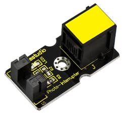
This is a high performance EASY Plug photo interrupter module.
The upright part on the module combines an infrared light emitting diode and shielded infrared detector.
By emitting a beam of infrared light from one end to another end, the sensor can detect an object when it passes through the beam.
Useful for many applications such as optical limit switches, pellet dispensing, general object detection, etc.
This module needs to be used together with EASY plug control board.
Special Note:
The sensor/module is equipped with the RJ11 6P6C interface, compatible with our keyestudio EASY plug Control Board with RJ11 6P6C interface.
If you have the control board of other brands, it is also equipped with the RJ11 6P6C interface but has different internal line sequence, can’t be used compatibly with our sensor/module.
Specification
- Connector: Easy plug
- Supply Voltage: 3.3V to 5V
- Interface: Digital
Technical Details
- Dimensions: 38mm*20mm*18mm
- Weight: 4.8g
Connect It Up
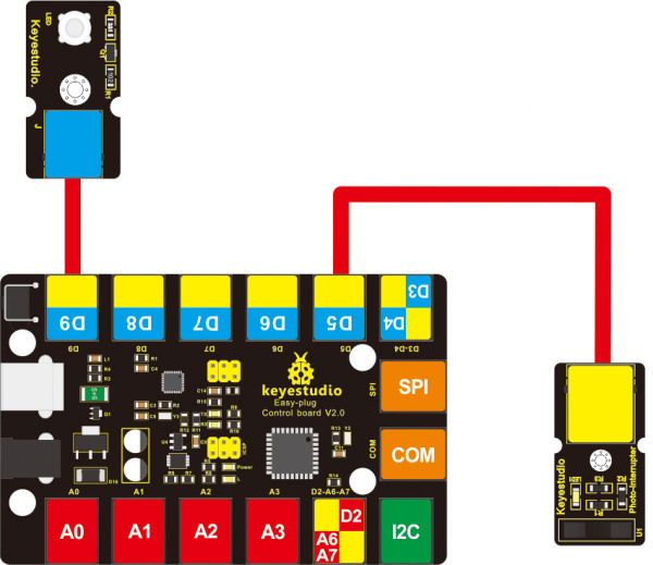
Connect the EASY Plug Photo Interrupter module and LED module to control board using RJ11 cables. Then connect the control board to your PC with a USB cable.
Upload the Code
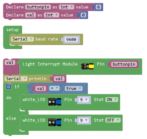
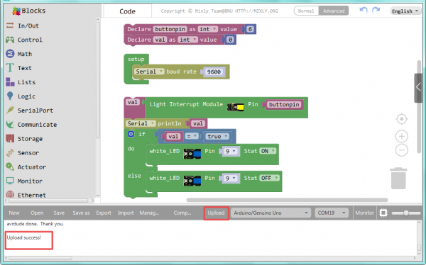
Below is an example code. Open or drag below code to Mixly Blocks and upload.
What You Should See
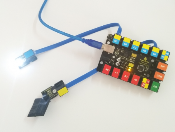
Done uploading the code, powered on, if pick up a piece of paper to cover the light on the groove part of module, you should see the LED is turned on. If no interruption, the LED is off.
Extension Experiment
Adding 4-digit LED Display
Hookup Guide
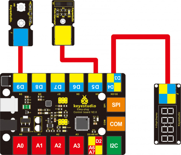
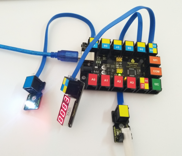
Connect the EASY Plug crash sensor, 4-digit LED display and LED module to control board using RJ11 cables.
Upload the Code
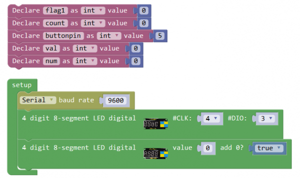
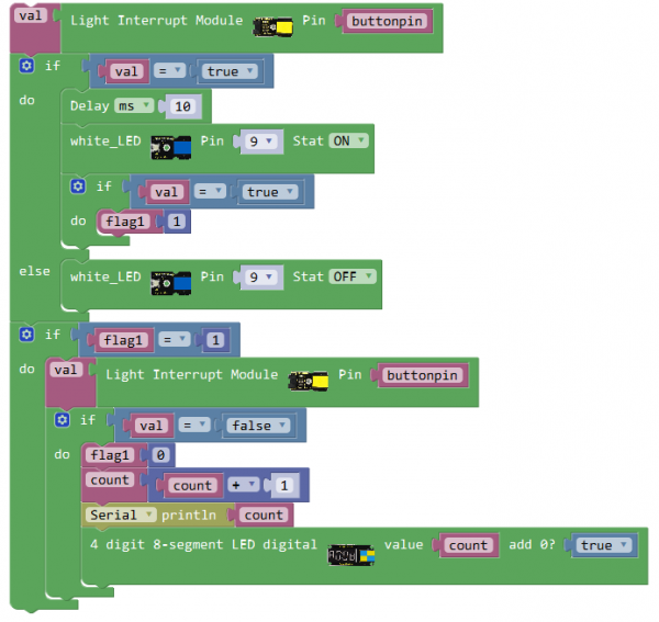
Below is an example code.
What You Should See
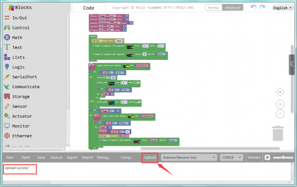
Done uploading the code, if pick up a piece of paper to cover the light on the groove part, the LED is turned on. If no interruption, the LED is off.
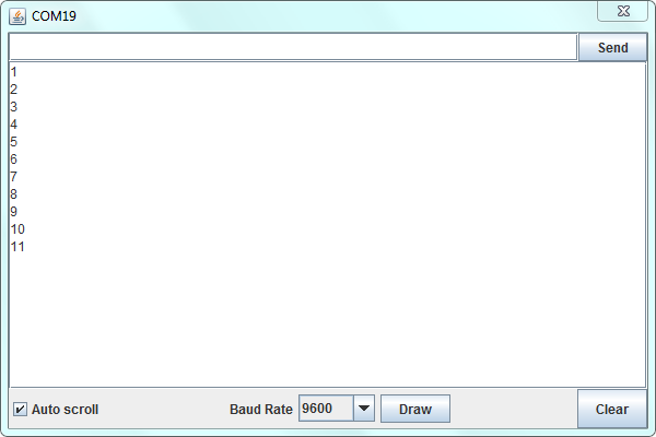
You should be able to see the number of covering the light is showed on the 4-digit LED display, or on the monitor.
Resources
https://fs.keyestudio.com/KS0121
