KS0369 EASY plug 4-Digit LED Display: Difference between revisions
Keyestudio (talk | contribs) No edit summary |
Keyestudio (talk | contribs) |
||
| (10 intermediate revisions by the same user not shown) | |||
| Line 7: | Line 7: | ||
The four pins of LED display are GND、VCC、DIO、CLK. (GND is ground, VCC is for power supply, DIO is data IO pin, CLK is clock signal pin.) <br> | The four pins of LED display are GND、VCC、DIO、CLK. (GND is ground, VCC is for power supply, DIO is data IO pin, CLK is clock signal pin.) <br> | ||
The module pins are extended into Registered jack, so you can easily connect it to EASY Plug control board using a RJ11 cable.<br> | The module pins are extended into Registered jack, so you can easily connect it to EASY Plug control board using a RJ11 cable.<br> | ||
<span style= | This module should be used together with EASY plug control board.<br> | ||
<span style=color:red> '''Special Note:''' <br> | |||
The sensor/module is equipped with the RJ11 6P6C interface, compatible with our keyestudio EASY plug Control Board with RJ11 6P6C interface. <br> If you have the control board of other brands, it is also equipped with the RJ11 6P6C interface but has different internal line sequence, can’t be used compatibly with our sensor/module. </span><br> | |||
<br> | <br> | ||
| Line 27: | Line 31: | ||
==Upload the Code== | ==Upload the Code== | ||
Below is an example code. Open or drag below code to [https://wiki.keyestudio.com/Getting_Started_with_Mixly Mixly Blocks] and upload. <br> | Below is an example code. Open or drag below code to [https://wiki.keyestudio.com/Getting_Started_with_Mixly Mixly Blocks] and upload. <br> | ||
<br>[[File:ks0397 9.1.1.png| | <br>[[File:ks0397 9.1.1.png|600px|frameless|thumb]]<br> | ||
<br>[[File:ks0397 9.1.2.png| | <br>[[File:ks0397 9.1.2.png|600px|frameless|thumb]]<br> | ||
<br> | <br> | ||
==What You Should See== | ==What You Should See== | ||
After uploading the code, you should see the 4-digit LED display show the number jumping. <br> | After uploading the code, you should see the 4-digit LED display show the number jumping. <br> | ||
| Line 42: | Line 47: | ||
* '''Compiling Fails ?'''<br> | * '''Compiling Fails ?'''<br> | ||
This happens sometimes, the most likely case is a library file not added. You should be sure all the libraries under the '''KS_EasyPulg''' are added to the libraries directory of Arduino-1.8.5. Shown below.<br> | This happens sometimes, the most likely case is a library file not added. You should be sure all the libraries under the '''KS_EasyPulg''' are added to the libraries directory of Arduino-1.8.5. Shown below.<br> | ||
<br>[[File:0397libraries 1.png| | <br>[[File:0397libraries 1.png|600px|frameless|thumb]]<br> | ||
<br>[[File:0397libraries 2.png| | <br>[[File:0397libraries 2.png|600px|frameless|thumb]]<br> | ||
<br>[[File:0397libraries 3.png| | <br>[[File:0397libraries 3.png|600px|frameless|thumb]]<br> | ||
<br> | <br> | ||
* '''Program Not Uploading?'''<br> | * '''Program Not Uploading?'''<br> | ||
This happens sometimes, the most likely case is a confused Board and serial port, you should firstly select your proper board and port. <br> | This happens sometimes, the most likely case is a confused Board and serial port, you should firstly select your proper board and port. <br> | ||
<br>[[File:ks0397 9-1.png| | <br>[[File:ks0397 9-1.png|600px|frameless|thumb]]<br> | ||
<br> | <br> | ||
==Extension Experiment 1== | ==Extension Experiment 1== | ||
<br> | <br> | ||
<span style=color:brown>'''Time Counting'''</span><br> | <span style=color:brown><big>'''Time Counting'''</big></span><br> | ||
<br> | <br> | ||
| Line 62: | Line 68: | ||
<br>[[File:KS0369.jpg|600px|frameless|thumb]]<br> | <br>[[File:KS0369.jpg|600px|frameless|thumb]]<br> | ||
'''Test Code'''<br> | '''Test Code'''<br> | ||
Below is an example code. | Below is an example code. | ||
<br>[[File:ks0397 9.2.png| | <br>[[File:ks0397 9.2.png|600px|frameless|thumb]]<br> | ||
<br> | <br> | ||
'''What You Should See'''<br> | '''What You Should See'''<br> | ||
Upload the code success. | |||
<br>[[File:ks0397 9-4.png|500px|frameless|thumb]]<br> | <br>[[File:ks0397 9-4.png|500px|frameless|thumb]]<br> | ||
| Line 75: | Line 81: | ||
<br> | <br> | ||
==Extension Experiment 2 == | ==Extension Experiment 2 == | ||
<br> | <br> | ||
<span style=color:brown>Counting And Reset'''</span><br> | <span style=color:brown><big>'''Counting And Reset'''</big></span><br> | ||
<br> | <br> | ||
'''Hookup Guide'''<br> | '''Hookup Guide'''<br> | ||
| Line 86: | Line 93: | ||
'''Test Code'''<br> | '''Test Code'''<br> | ||
Below is an example code. | Below is an example code. | ||
<br>[[File:ks0397 9.3.1.png| | <br>[[File:ks0397 9.3.1.png|600px|frameless|thumb]]<br> | ||
<br>[[File:ks0397 9.3.2.png|500px|frameless|thumb]]<br> | <br>[[File:ks0397 9.3.2.png|500px|frameless|thumb]]<br> | ||
<br>[[File:ks0397 9.3.3.png| | <br>[[File:ks0397 9.3.3.png|600px|frameless|thumb]]<br> | ||
<br> | <br> | ||
| Line 98: | Line 105: | ||
==Resources == | ==Resources == | ||
https://fs.keyestudio.com/KS0369 | |||
https:// | |||
<br> | <br> | ||
==Buy from == | ==Buy from == | ||
*[https://www.keyestudio.com/keyestudio-easy-plug-4-digit-led-display-module-for-arduino-stem-p0504-p0504.html '''Official Website'''] | *[https://www.keyestudio.com/keyestudio-easy-plug-4-digit-led-display-module-for-arduino-stem-p0504-p0504.html '''Official Website'''] | ||
Latest revision as of 08:43, 8 January 2021
Introduction
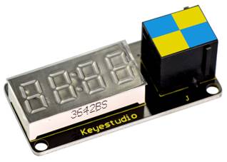
This is a 4-digit 0.36’’ Common Anode LED display module, a 12-pin display module with score points.
The driver chip used in the matrices is TM1637, using only two signal cables to make the microcontroller control the 4-digit LED display.
The four pins of LED display are GND、VCC、DIO、CLK. (GND is ground, VCC is for power supply, DIO is data IO pin, CLK is clock signal pin.)
The module pins are extended into Registered jack, so you can easily connect it to EASY Plug control board using a RJ11 cable.
This module should be used together with EASY plug control board.
Special Note:
The sensor/module is equipped with the RJ11 6P6C interface, compatible with our keyestudio EASY plug Control Board with RJ11 6P6C interface.
If you have the control board of other brands, it is also equipped with the RJ11 6P6C interface but has different internal line sequence, can’t be used compatibly with our sensor/module.
Parameters
- Operating Voltage: DC5V
- Operating Temperature Range: -40~+85℃
- Property: ROHS
Technical Details
- Dimensions: 50mm*23mm*18mm
- Weight: 9g
Connect It Up
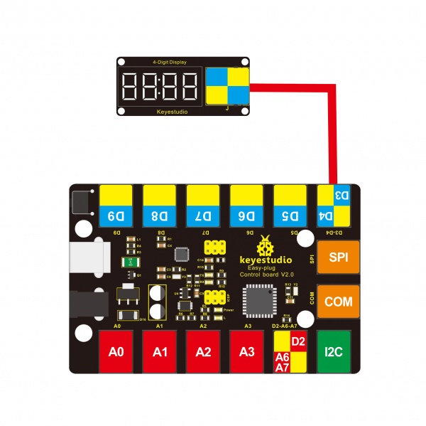
Connect the EASY Plug 4-Digit LED display to control board using an RJ11 cable. Then connect the control board to your PC with a USB cable.
Upload the Code
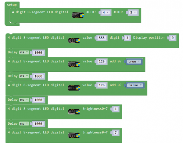
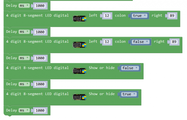
Below is an example code. Open or drag below code to Mixly Blocks and upload.
What You Should See
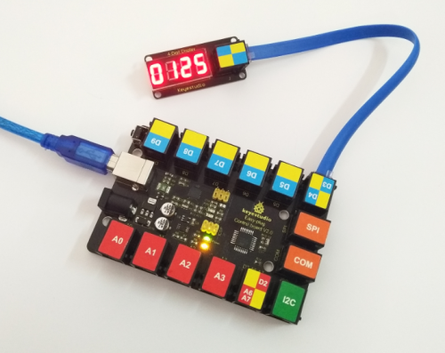
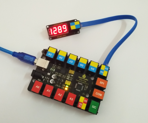
After uploading the code, you should see the 4-digit LED display show the number jumping.
On the left side, show 555; after one second, show 0125 on the right side; after one second, show 125; then after one second, the display brightness is 1, becoming rather darker. One second later, the display brightness is 7, becoming rather brighter.
After one second again, show the 12:89; then one second later, do not show the colon. After one second, the LED display is off; and one second later, start to repeat the display again.
Troubleshooting:
- Compiling Fails ?
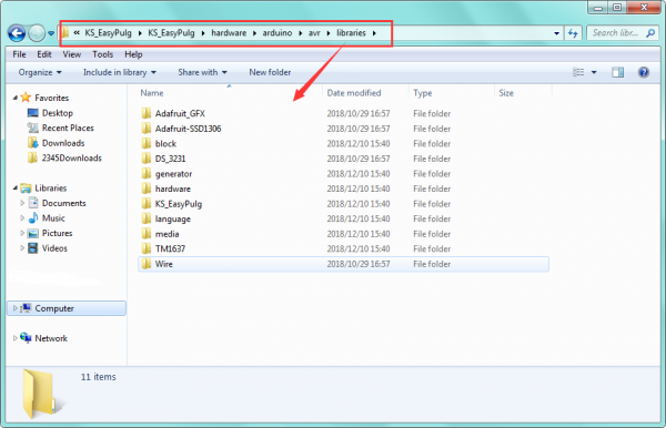
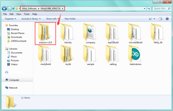
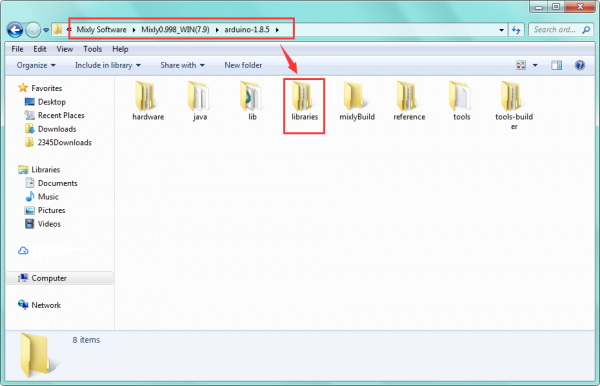
This happens sometimes, the most likely case is a library file not added. You should be sure all the libraries under the KS_EasyPulg are added to the libraries directory of Arduino-1.8.5. Shown below.
- Program Not Uploading?
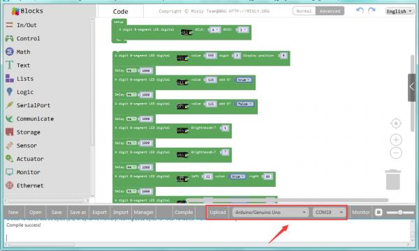
This happens sometimes, the most likely case is a confused Board and serial port, you should firstly select your proper board and port.
Extension Experiment 1
Time Counting
Hookup Guide
Connect the EASY Plug 4-digit LED display module to control board using an RJ11 cable.

Test Code
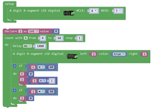
Below is an example code.
What You Should See
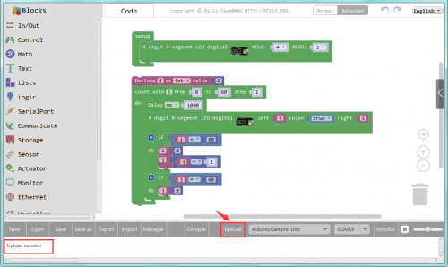
Upload the code success.
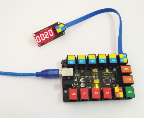
The 4-digit LED display starts to show the time counting. Seconds on the right, minutes on the left, and return to zero after 60 minutes.
Extension Experiment 2
Counting And Reset
Hookup Guide
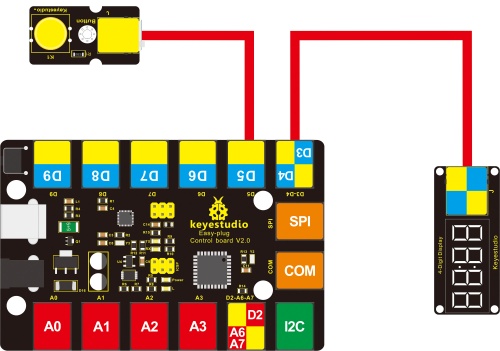
Connect the EASY Plug 4-digit LED display module and button module to control board using RJ11 cables.
Test Code
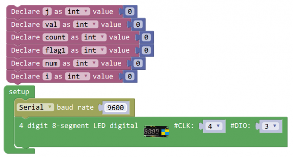
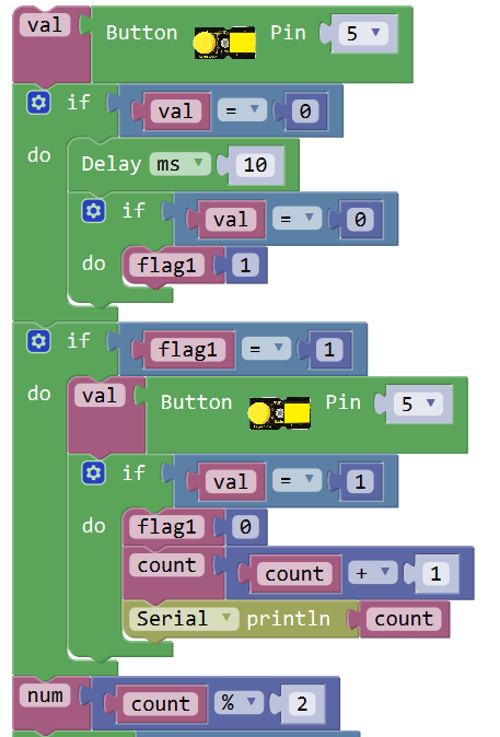
Below is an example code.
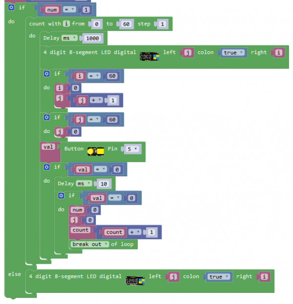
What You Should See
The 4-digit LED display starts to show the time counting. If press the button, it will reset the counting.
Resources
https://fs.keyestudio.com/KS0369
