Ks0165 Keyestudio Scratch Shield: Difference between revisions
Keyestudio (talk | contribs) (Created blank page) |
Keyestudio (talk | contribs) |
||
| (One intermediate revision by the same user not shown) | |||
| Line 1: | Line 1: | ||
<br> | |||
==Keyestudio Scratch Shield== | |||
<br>[[File:Ks0165.png|500px|frameless|thumb]]<br> | |||
<br> | |||
==Introduction== | |||
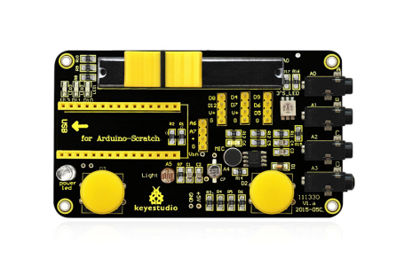
keyestudio Scratch shield is used with Arduino Nano. Using the Scratch programming language, you can easily create simple interactive programs with Arduino or create programs based on the input of Arduino from sensors. <br> | |||
keyestudio Robotale Scratch incorporates a light sensor, sound sensor, a button and a slider, as well as 4 additional inputs that can sense electrical resistance via cables. <br> | |||
Designed for educators and beginners, keyestudio Robotale Scratch is a good way to get into the very basics of programming and reading sensors.<br> | |||
<br> | |||
==Specification== | |||
* Use with Nano development board | |||
* Incorporate a light sensor, sound sensor, a button and a slider | |||
* S4A simple programming | |||
<br> | |||
==User Instruction== | |||
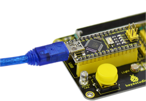
1. Connect Nano development board to the computer, use Arduino IDE for firmware uploading. <br> | |||
2. Open S4A, click “Costumes”-Import to import new costumes.<br> | |||
3. Click “Script”, write the control script using blocks of the control group. <br> | |||
4. After completing the control script, click [[File:ks0165-2.png|500px|frameless|thumb]] to run the script.<br> | |||
<br> | |||
==Circuit Connection == | |||
<br>[[File:KS0165.png|500px|frameless|thumb]]<br> | |||
<br> | |||
==Sample Code== | |||
Code Download:[http://www.keyestudio.com/files/index/download/id/1508115422/] or you can directly copy the below code.<br> | |||
<pre> | |||
// NEW IN VERSION 1.5: | |||
// Changed pin 8 from standard servo to normal digital output | |||
// NEW IN VERSION 1.4: | |||
// Changed Serial.print() for Serial.write() in ScratchBoardSensorReport function to make it compatible with latest Arduino IDE (1.0) | |||
// NEW IN VERSION 1.3: | |||
// Now it works on GNU/Linux. Also tested with MacOS and Windows 7. | |||
// timer2 set to 20ms, fixing a glitch that made this period unstable in previous versions. | |||
// readSerialport() function optimized. | |||
// pulse() modified so that it receives pulse width as a parameter instead using a global variable. | |||
// updateServoMotors changes its name as a global variable had the same name. | |||
// Some minor fixes. | |||
// Thanks to Jorge Gomez for all these new fixes! | |||
#define TIMER2_PRELOAD 100 | |||
char outputs[10]; | |||
int states[10]; | |||
unsigned long initialPulseTime; | |||
unsigned long lastDataReceivedTime; | |||
volatile boolean updateServoMotors; | |||
volatile boolean newInterruption; | |||
void setup() | |||
{ | |||
Serial.begin(38400); | |||
Serial.flush(); | |||
configurePins(); | |||
configureServomotors(); | |||
lastDataReceivedTime = millis(); | |||
} | |||
void loop() | |||
{ | |||
if (updateServoMotors) | |||
{ | |||
sendUpdateServomotors(); | |||
sendSensorValues(); | |||
updateServoMotors = false; | |||
} | |||
else | |||
{ | |||
readSerialPort(); | |||
} | |||
} | |||
void configurePins() | |||
{ | |||
for (int index = 0; index < 10; index++) | |||
{ | |||
states[index] = 0; | |||
pinMode(index+4, OUTPUT); | |||
digitalWrite(index+4, LOW); //reset pins | |||
} | |||
pinMode(2,INPUT); | |||
pinMode(3,INPUT); | |||
outputs[0] = 'c'; //pin 4 | |||
outputs[1] = 'a'; //pin 5 | |||
outputs[2] = 'a'; //pin 6 | |||
outputs[3] = 'c'; //pin 7 | |||
outputs[4] = 's'; //pin 8 | |||
outputs[5] = 'a'; //pin 9 | |||
outputs[6] = 'd'; //pin 10 | |||
outputs[7] = 'd'; //pin 11 | |||
outputs[8] = 'd'; //pin 12 | |||
outputs[9] = 'd'; //pin 13 | |||
} | |||
void configureServomotors() //servomotors interruption configuration (interruption each 10 ms on timer2) | |||
{ | |||
newInterruption = false; | |||
updateServoMotors = false; | |||
TCCR2A = 0; | |||
TCCR2B = 1<<CS22 | 1<<CS21 | 1<<CS20; | |||
TIMSK2 = 1<<TOIE2; //timer2 Overflow Interrupt | |||
TCNT2 = TIMER2_PRELOAD; //start timer | |||
} | |||
void sendSensorValues() | |||
{ | |||
int sensorValues[6], readings[5], sensorIndex; | |||
for (sensorIndex = 0; sensorIndex < 6; sensorIndex++) //for analog sensors, calculate the median of 5 sensor readings in order to avoid variability and power surges | |||
{ | |||
for (int p = 0; p < 5; p++) | |||
readings[p] = analogRead(sensorIndex); | |||
InsertionSort(readings, 5); //sort readings | |||
sensorValues[sensorIndex] = readings[2]; //select median reading | |||
} | |||
//send analog sensor values | |||
for (sensorIndex = 0; sensorIndex < 6; sensorIndex++) | |||
ScratchBoardSensorReport(sensorIndex, sensorValues[sensorIndex]); | |||
//send digital sensor values | |||
ScratchBoardSensorReport(6, digitalRead(2)?1023:0); | |||
ScratchBoardSensorReport(7, digitalRead(3)?1023:0); | |||
} | |||
void InsertionSort(int* array, int n) | |||
{ | |||
for (int i = 1; i < n; i++) | |||
for (int j = i; (j > 0) && ( array[j] < array[j-1] ); j--) | |||
swap( array, j, j-1 ); | |||
} | |||
void swap (int* array, int a, int b) | |||
{ | |||
int temp = array[a]; | |||
array[a] = array[b]; | |||
array[b] = temp; | |||
} | |||
void ScratchBoardSensorReport(int sensor, int value) //PicoBoard protocol, 2 bytes per sensor | |||
{ | |||
Serial.write( B10000000 | |||
| ((sensor & B1111)<<3) | |||
| ((value>>7) & B111)); | |||
Serial.write( value & B1111111); | |||
} | |||
void readSerialPort() | |||
{ | |||
int pin, inByte, sensorHighByte; | |||
if (Serial.available() > 1) | |||
{ | |||
lastDataReceivedTime = millis(); | |||
inByte = Serial.read(); | |||
if (inByte >= 128) // Are we receiving the word's header? | |||
{ | |||
sensorHighByte = inByte; | |||
pin = ((inByte >> 3) & 0x0F); | |||
while (!Serial.available()); // Wait for the end of the word with data | |||
inByte = Serial.read(); | |||
if (inByte <= 127) // This prevents Linux ttyACM driver to fail | |||
{ | |||
states[pin - 4] = ((sensorHighByte & 0x07) << 7) | (inByte & 0x7F); | |||
updateActuator(pin - 4); | |||
} | |||
} | |||
} | |||
else checkScratchDisconnection(); | |||
} | |||
void reset() //with xbee module, we need to simulate the setup execution that occurs when a usb connection is opened or closed without this module | |||
{ | |||
for (int pos = 0; pos < 10; pos++) //stop all actuators | |||
{ | |||
states[pos] = 0; | |||
digitalWrite(pos + 2, LOW); | |||
} | |||
//reset servomotors | |||
newInterruption = false; | |||
updateServoMotors = false; | |||
TCNT2 = TIMER2_PRELOAD; | |||
//protocol handshaking | |||
sendSensorValues(); | |||
lastDataReceivedTime = millis(); | |||
} | |||
void updateActuator(int pinNumber) | |||
{ | |||
if (outputs[pinNumber] == 'd') digitalWrite(pinNumber + 4, states[pinNumber]); | |||
else if (outputs[pinNumber] == 'a') analogWrite(pinNumber + 4, states[pinNumber]); | |||
} | |||
void sendUpdateServomotors() | |||
{ | |||
for (int p = 0; p < 10; p++) | |||
{ | |||
if (outputs[p] == 'c') servomotorC(p + 4, states[p]); | |||
if (outputs[p] == 's') servomotorS(p + 4, states[p]); | |||
} | |||
} | |||
void servomotorC (int pinNumber, int dir) | |||
{ | |||
if (dir == 1) pulse(pinNumber, 1300); //clockwise rotation | |||
else if (dir == 2) pulse(pinNumber, 1700); //anticlockwise rotation | |||
} | |||
void servomotorS (int pinNumber, int angle) | |||
{ | |||
if (angle < 0) pulse(pinNumber, 600); | |||
else if (angle > 180) pulse(pinNumber, 2400); | |||
else pulse(pinNumber, (angle * 10) + 600); | |||
} | |||
void pulse (int pinNumber, int pulseWidth) | |||
{ | |||
initialPulseTime = micros(); | |||
digitalWrite(pinNumber, HIGH); | |||
while (micros() < pulseWidth + initialPulseTime){} | |||
digitalWrite(pinNumber, LOW); | |||
} | |||
void checkScratchDisconnection() //the reset is necessary when using an wireless arduino board (because we need to ensure that arduino isn't waiting the actuators state from Scratch) or when scratch isn't sending information (because is how serial port close is detected) | |||
{ | |||
if (millis() - lastDataReceivedTime > 1000) reset(); //reset state if actuators reception timeout = one second | |||
} | |||
ISR(TIMER2_OVF_vect) //timer1 overflow interrupt vector handler | |||
{ //timer2 => 8 bits counter => 256 clock ticks | |||
//preeescaler = 1024 => this routine is called 61 (16.000.000/256/1024) times per second approximately => interruption period = 1 / 16.000.000/256/1024 = 16,384 ms | |||
//as we need a 20 ms interruption period but timer2 doesn't have a suitable preescaler for this, we program the timer with a 10 ms interruption period and we consider an interruption every 2 times this routine is called. | |||
//to have a 10 ms interruption period, timer2 counter must overflow after 156 clock ticks => interruption period = 1 / 16.000.000/156/1024 = 9,984 ms => counter initial value (TCNT) = 100 | |||
if (newInterruption) | |||
{ | |||
updateServoMotors = true; | |||
} | |||
newInterruption = !newInterruption; | |||
TCNT2 = TIMER2_PRELOAD; //reset timer | |||
} | |||
</pre> | |||
<br> | |||
==Script edit== | |||
* '''Script 1:<br>''' | |||
<br>[[File:ks0165-4.png|600px|frameless|thumb]]<br> | |||
<br> | |||
* '''Script 2:<br>''' | |||
<br>[[File:ks0165-5.png|600px|frameless|thumb]]<br> | |||
<br> | |||
==Result== | |||
* '''For script 1:''' <br> | |||
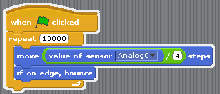
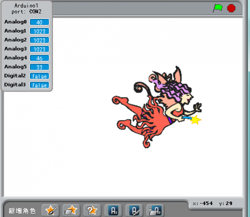
Click [[File:ks0165-2.png|500px|frameless|thumb]] , the costume moves freely; bounce back when it hits the edge. <br> | |||
Move the slider on the shield to change the value in Analog0, the greater the value, the faster the costume moves. <br> | |||
<br>[[File:ks0165-6.png|500px|frameless|thumb]]<br> | |||
<br> | |||
* '''For script 2:''' <br> | |||
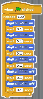
Click [[File:ks0165-2.png|500px|frameless|thumb]], the D10, D11, D13 LEDs on the shield displays light chasing effect; stops after 100 cycles. | |||
<br> | |||
== Resources == | |||
* '''Code Download of Robotale Scratch:'''<br> | |||
https://fs.keyestudio.com/KS0165 | |||
* '''Video:'''<br> | |||
http://video.keyestudio.com/ks0165/ | |||
<br> | |||
== Buy From == | |||
*[https://www.keyestudio.com/free-shipping-keyestudio-robotale-scratch-for-arduino-nano-p0490-p0490.html '''Official Website'''] | |||
[[Category:Module]] | |||
Latest revision as of 11:28, 8 January 2021
Keyestudio Scratch Shield
Introduction
keyestudio Scratch shield is used with Arduino Nano. Using the Scratch programming language, you can easily create simple interactive programs with Arduino or create programs based on the input of Arduino from sensors.
keyestudio Robotale Scratch incorporates a light sensor, sound sensor, a button and a slider, as well as 4 additional inputs that can sense electrical resistance via cables.
Designed for educators and beginners, keyestudio Robotale Scratch is a good way to get into the very basics of programming and reading sensors.
Specification
- Use with Nano development board
- Incorporate a light sensor, sound sensor, a button and a slider
- S4A simple programming
User Instruction
1. Connect Nano development board to the computer, use Arduino IDE for firmware uploading.
2. Open S4A, click “Costumes”-Import to import new costumes.
3. Click “Script”, write the control script using blocks of the control group.
4. After completing the control script, click  to run the script.
Circuit Connection
Sample Code
Code Download:[1] or you can directly copy the below code.
// NEW IN VERSION 1.5:
// Changed pin 8 from standard servo to normal digital output

// NEW IN VERSION 1.4:
// Changed Serial.print() for Serial.write() in ScratchBoardSensorReport function to make it compatible with latest Arduino IDE (1.0)

// NEW IN VERSION 1.3:
// Now it works on GNU/Linux. Also tested with MacOS and Windows 7.
// timer2 set to 20ms, fixing a glitch that made this period unstable in previous versions.
// readSerialport() function optimized.
// pulse() modified so that it receives pulse width as a parameter instead using a global variable.
// updateServoMotors changes its name as a global variable had the same name.
// Some minor fixes.

// Thanks to Jorge Gomez for all these new fixes!

#define TIMER2_PRELOAD 100

char outputs[10];
int states[10];

unsigned long initialPulseTime;
unsigned long lastDataReceivedTime;

volatile boolean updateServoMotors;
volatile boolean newInterruption;

void setup()
{
 Serial.begin(38400);
 Serial.flush();
 configurePins();
 configureServomotors();
 lastDataReceivedTime = millis();
}

void loop()
{
 if (updateServoMotors)
 {
   sendUpdateServomotors();
   sendSensorValues();
   updateServoMotors = false;
 }
 else
 {
   readSerialPort();
 }
}

void configurePins()
{
 for (int index = 0; index < 10; index++)
 {
    states[index] = 0;
    pinMode(index+4, OUTPUT);
    digitalWrite(index+4, LOW); //reset pins
 }

 pinMode(2,INPUT);
 pinMode(3,INPUT);

 outputs[0] = 'c'; //pin 4
 outputs[1] = 'a'; //pin 5
 outputs[2] = 'a'; //pin 6
 outputs[3] = 'c'; //pin 7
 outputs[4] = 's'; //pin 8
 outputs[5] = 'a'; //pin 9
 outputs[6] = 'd'; //pin 10
 outputs[7] = 'd'; //pin 11
 outputs[8] = 'd'; //pin 12
 outputs[9] = 'd'; //pin 13
}

void configureServomotors() //servomotors interruption configuration (interruption each 10 ms on timer2)
{
 newInterruption = false;
 updateServoMotors = false;

 TCCR2A = 0;
 TCCR2B = 1<<CS22 | 1<<CS21 | 1<<CS20;
 TIMSK2 = 1<<TOIE2; //timer2 Overflow Interrupt
 TCNT2 = TIMER2_PRELOAD; //start timer
}

void sendSensorValues()
{
  int sensorValues[6], readings[5], sensorIndex;
    for (sensorIndex = 0; sensorIndex < 6; sensorIndex++) //for analog sensors, calculate the median of 5 sensor readings in order to avoid variability and power surges
    {
      for (int p = 0; p < 5; p++)
        readings[p] = analogRead(sensorIndex);
      InsertionSort(readings, 5); //sort readings
      sensorValues[sensorIndex] = readings[2]; //select median reading
    }

    //send analog sensor values
    for (sensorIndex = 0; sensorIndex < 6; sensorIndex++)
      ScratchBoardSensorReport(sensorIndex, sensorValues[sensorIndex]);

    //send digital sensor values
    ScratchBoardSensorReport(6, digitalRead(2)?1023:0);
    ScratchBoardSensorReport(7, digitalRead(3)?1023:0);
}

void InsertionSort(int* array, int n)
{
  for (int i = 1; i < n; i++)
    for (int j = i; (j > 0) && ( array[j] < array[j-1] ); j--)
      swap( array, j, j-1 );
}

void swap (int* array, int a, int b)
{
  int temp = array[a];
  array[a] = array[b];
  array[b] = temp;
}

void ScratchBoardSensorReport(int sensor, int value) //PicoBoard protocol, 2 bytes per sensor
{
  Serial.write( B10000000
                | ((sensor & B1111)<<3)
                | ((value>>7) & B111));
  Serial.write( value & B1111111);
}

void readSerialPort()
{
  int pin, inByte, sensorHighByte;

  if (Serial.available() > 1)
  {
    lastDataReceivedTime = millis();
    inByte = Serial.read();

    if (inByte >= 128) // Are we receiving the word's header?
    {
      sensorHighByte = inByte;
      pin = ((inByte >> 3) & 0x0F);
      while (!Serial.available()); // Wait for the end of the word with data
      inByte = Serial.read();
      if (inByte <= 127) // This prevents Linux ttyACM driver to fail
      {
        states[pin - 4] = ((sensorHighByte & 0x07) << 7) | (inByte & 0x7F);
          updateActuator(pin - 4);
      }
    }
  }
  else checkScratchDisconnection();
}

void reset() //with xbee module, we need to simulate the setup execution that occurs when a usb connection is opened or closed without this module
{
  for (int pos = 0; pos < 10; pos++)  //stop all actuators
  {
    states[pos] = 0;
    digitalWrite(pos + 2, LOW);
  }

  //reset servomotors
  newInterruption = false;
  updateServoMotors = false;
  TCNT2 = TIMER2_PRELOAD;

  //protocol handshaking
  sendSensorValues();
  lastDataReceivedTime = millis();
}

void updateActuator(int pinNumber)
{
  if (outputs[pinNumber] == 'd')  digitalWrite(pinNumber + 4, states[pinNumber]);
  else if (outputs[pinNumber] == 'a')  analogWrite(pinNumber + 4, states[pinNumber]);
}

void sendUpdateServomotors()
{
  for (int p = 0; p < 10; p++)
  {
    if (outputs[p] == 'c') servomotorC(p + 4, states[p]);
    if (outputs[p] == 's') servomotorS(p + 4, states[p]);
  }
}

void servomotorC (int pinNumber, int dir)
{
  if (dir == 1) pulse(pinNumber, 1300); //clockwise rotation
  else if (dir == 2) pulse(pinNumber, 1700); //anticlockwise rotation
}

void servomotorS (int pinNumber, int angle)
{
  if (angle < 0) pulse(pinNumber, 600);
  else if (angle > 180) pulse(pinNumber, 2400);
  else pulse(pinNumber, (angle * 10) + 600);
}

void pulse (int pinNumber, int pulseWidth)
{
  initialPulseTime = micros();
  digitalWrite(pinNumber, HIGH);

  while (micros() < pulseWidth + initialPulseTime){}
  digitalWrite(pinNumber, LOW);
}

void checkScratchDisconnection() //the reset is necessary when using an wireless arduino board (because we need to ensure that arduino isn't waiting the actuators state from Scratch) or when scratch isn't sending information (because is how serial port close is detected)
{
  if (millis() - lastDataReceivedTime > 1000) reset(); //reset state if actuators reception timeout = one second
}

ISR(TIMER2_OVF_vect) //timer1 overflow interrupt vector handler
{ //timer2 => 8 bits counter => 256 clock ticks
  //preeescaler = 1024 => this routine is called 61 (16.000.000/256/1024) times per second approximately => interruption period =  1 / 16.000.000/256/1024 = 16,384 ms
  //as we need a 20 ms interruption period but timer2 doesn't have a suitable preescaler for this, we program the timer with a 10 ms interruption period and we consider an interruption every 2 times this routine is called.
  //to have a 10 ms interruption period, timer2 counter must overflow after 156 clock ticks => interruption period = 1 / 16.000.000/156/1024 = 9,984 ms => counter initial value (TCNT) = 100
  if (newInterruption)
  {
    updateServoMotors = true;
  }
  newInterruption = !newInterruption;
  TCNT2 = TIMER2_PRELOAD;  //reset timer
}
Script edit
- Script 1:
- Script 2:
Result
- For script 1:
Click  , the costume moves freely; bounce back when it hits the edge.
Move the slider on the shield to change the value in Analog0, the greater the value, the faster the costume moves.
- For script 2:
Click  , the D10, D11, D13 LEDs on the shield displays light chasing effect; stops after 100 cycles.
Resources
- Code Download of Robotale Scratch:
https://fs.keyestudio.com/KS0165
- Video:
http://video.keyestudio.com/ks0165/
