KS0460 keyestudio Logic DC Jack Module: Difference between revisions
Keyestudio (talk | contribs) |
Keyestudio (talk | contribs) |
||
| (7 intermediate revisions by the same user not shown) | |||
| Line 1: | Line 1: | ||
[[Image:Ks0460-1.png|500px|frameless]]<br> | [[Image:Ks0460-1.png|500px|frameless|right]]<br> | ||
<br> | <br> | ||
== Description == | == Description == | ||
When we design program to do experiments, we often need to use logical transformation. <br> | When we design program to do experiments, we often need to use logical transformation. <br> | ||
The keyestudio Logic DC jack module comes with a logic conversion function that includes AND gates and | The keyestudio Logic DC jack module comes with a logic conversion function that includes AND gates and NOT gates.<br> | ||
When in use, the toggle switch is turned to the "OFF" terminal, there is no output; when the toggle switch is toggled at the "SW1" terminal, the logic | When in use, the toggle switch is turned to the "OFF" terminal, there is no output; when the toggle switch is toggled at the "SW1" terminal, the logic NOT gate function is implemented, and the IN1 input level and the OUT output level are opposite; <br> | ||
When the switch is toggled at the "ON" terminal, logic and function are implemented, and the IN1 level and the IN2 level are combined to obtain the OUT level.<br> | When the switch is toggled at the "ON" terminal, logic and function are implemented, and the IN1 level and the IN2 level are combined to obtain the OUT level.<br> | ||
The working voltage of the module is 5V. <br> | The working voltage of the module is 5V. <br> | ||
There are two power | There are two ways for supplying power. The first way is to connect 5V power supply to GND and VCC; the aother way is to connect the DC 5.5-15V power supply to the black DC head of the module. <br> | ||
'''Special Note: When the module is connected to external power supply and other MCUs. The module must be connected to the microcontroller for common (GND) ground connection.'''<br> | <span style="color:red"><br>'''Special Note: When the module is connected to external power supply and other MCUs. The module must be connected to the microcontroller for common (GND) ground connection.''' </span><br> | ||
<br> | <br> | ||
| Line 26: | Line 26: | ||
<br> | <br> | ||
== Wiring diagram == | == Wiring diagram == | ||
<br>[[Image:Ks0460-3.png| | <br>[[Image:Ks0460-3.png|600px|frameless]]<br> | ||
== Test Code == | == Test Code == | ||
| Line 36: | Line 36: | ||
pinMode(IN1,OUTPUT); | pinMode(IN1,OUTPUT); | ||
pinMode(IN2,OUTPUT); | pinMode(IN2,OUTPUT); | ||
} | } | ||
void loop() { | void loop() { | ||
| Line 49: | Line 49: | ||
delay(1000); | delay(1000); | ||
} | } | ||
</pre> | |||
<br> | <br> | ||
| Line 58: | Line 58: | ||
==Resource== | ==Resource== | ||
*'''Download all the relevant info from the link:'''<br> | *'''Download all the relevant info from the link:'''<br> | ||
https:// | https://fs.keyestudio.com/KS0460 | ||
<br> | |||
<br> | <br> | ||
==Buy from == | |||
*[https://keyestudio.com/keyestudio-logic-dc-jack-module-for-arduino-p0603.html '''Official Website'''] | |||
<br> | |||
[[category:Module]] | |||
Latest revision as of 09:19, 4 March 2021
Description
When we design program to do experiments, we often need to use logical transformation.
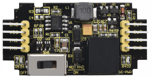
The keyestudio Logic DC jack module comes with a logic conversion function that includes AND gates and NOT gates.
When in use, the toggle switch is turned to the "OFF" terminal, there is no output; when the toggle switch is toggled at the "SW1" terminal, the logic NOT gate function is implemented, and the IN1 input level and the OUT output level are opposite;
When the switch is toggled at the "ON" terminal, logic and function are implemented, and the IN1 level and the IN2 level are combined to obtain the OUT level.
The working voltage of the module is 5V.
There are two ways for supplying power. The first way is to connect 5V power supply to GND and VCC; the aother way is to connect the DC 5.5-15V power supply to the black DC head of the module.
Special Note: When the module is connected to external power supply and other MCUs. The module must be connected to the microcontroller for common (GND) ground connection.
Technical parameters
- Working voltage: DC 5V
- External power supply: DC 5.5-15V
- Working current: external power supply up to 2A
- Maximum power: 7.5W
- Display color: black and white
- Operating temperature range: -20℃ to +60℃
- Size: 47*24*13mm<b
- Weight: 6.0g
- Environmental attributes: ROHS
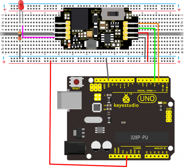
Wiring diagram
Test Code
#define IN1 2
#define IN2 3
void setup() {
  // put your setup code here, to run once:
pinMode(IN1,OUTPUT);
pinMode(IN2,OUTPUT);
}

void loop() {
  // put your main code here, to run repeatedly:
digitalWrite(IN1,LOW);
delay(1000);
digitalWrite(IN1,HIGH);
delay(2000);
digitalWrite(IN2,LOW);
delay(1000);
digitalWrite(IN2,HIGH);
delay(1000);
}
Test Result
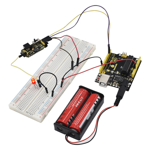
According to the wiring diagram, upload the test code successfully. After power-on, when the toggle switch is turned to the “OFF” end, the red LED is off; when the toggle switch is toggled at the “SW1” end, press the reset button on UNO R3 board, the red LED is on for 1 second, off for 4 seconds, alternately and circularly; when the toggle switch is toggled on the "ON" end, press the reset button on UNO R3 board, the red LED is off for 1 second, on for 2 seconds, and then off for 1 second, on for 1 second, alternately and circularly.

Resource
- Download all the relevant info from the link:
https://fs.keyestudio.com/KS0460
Buy from

