KS0453 Keyestudio 3-channel Line Tracking Module: Difference between revisions
Keyestudio (talk | contribs) |
Keyestudio (talk | contribs) |
||
| (4 intermediate revisions by the same user not shown) | |||
| Line 28: | Line 28: | ||
<br> | <br> | ||
== Wiring Diagram == | == Wiring Diagram == | ||
<br>[[File:Ks0453-3.png| | <br>[[File:Ks0453-3.png|700px|frameless|thumb]]<br> | ||
<br> | <br> | ||
== Test Code == | == Test Code == | ||
<pre> | <pre> | ||
| Line 66: | Line 67: | ||
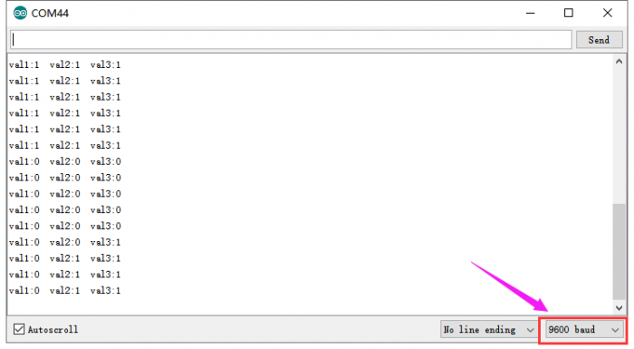
Done uploading the code to control board, open the serial monitor and set the baud rate to 9600. <br> | Done uploading the code to control board, open the serial monitor and set the baud rate to 9600. <br> | ||
When the tacking module detects black line, output 1; detecting white line, output 0. As figure shown below. | When the tacking module detects black line, output 1; detecting white line, output 0. As figure shown below. | ||
<br>[[File:Ks0453-4.png| | <br>[[File:Ks0453-4.png|700px|frameless|thumb]]<br> | ||
| Line 72: | Line 73: | ||
==Resource== | ==Resource== | ||
*'''Download all the relevant info. from the link:'''<br> | *'''Download all the relevant info. from the link:'''<br> | ||
https://fs.keyestudio.com/KS0453 | |||
<br> | |||
==Buy from == | ==Buy from == | ||
*[ '''Official Website'''] | *[ '''Official Website'''] | ||
Latest revision as of 09:37, 4 March 2021
Description
In the smart car DIY process, we often use a line tracking sensor to make the smart car follow a line.
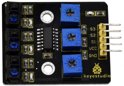
The keyestudio 3-channel line tracking module actually is an infrared sensor. The component used is a TCRT5000 infrared tube.
The working principle is to use the different reflectivity of infrared light to color, converting the strength of the reflected signal into a current signal.
During the detection, black is active at HIGH level, and white is active at LOW. The detection height is 0-3 cm.
We have integrated three groups of TCRT5000 infrared tubes on a single board, convenient for wiring and control.
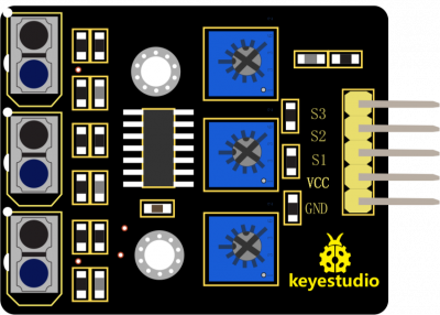
Turn the adjustable trimpot to adjust the module’s sensitivity.
The module comes with two 3mm positioning holes for mounting on other devices.
Note: before testing, turn the potentiometer to adjust the sensitivity. The sensitivity is the best when make the LED at the threshold point between ON and OFF.

Technical Parameters
- Operating voltage: DC 3.3-5V
- Detection height: 0—3cm
- Interface: 5pin of 2.54mm pitch
- Positioning hole diameter: 3mm
- Dimensions: 42mm*31mm*7mm
- Weight: 6.6g
- Environment attribute: ROHS
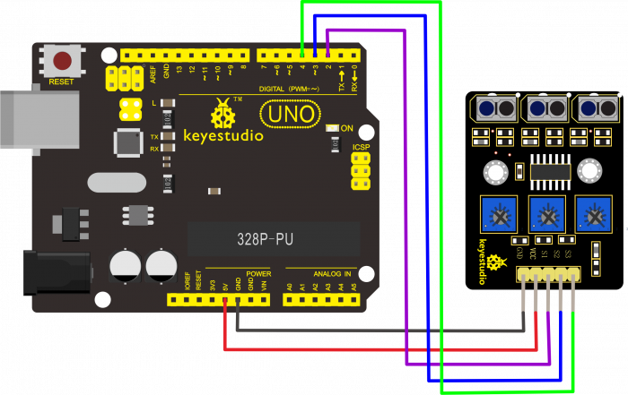
Wiring Diagram
Test Code
int sensor1 = 2;
int sensor2 = 3;
int sensor3 = 4;
int val1;
int val2;
int val3;
void setup()
{
  Serial.begin(9600);
  pinMode(sensor1, INPUT); // set sensor to input mode
  pinMode(sensor2, INPUT); // set sensor to input mode
  pinMode(sensor2, INPUT); // set sensor to input mode
}

void loop()
{
  val1=digitalRead(sensor1);
  Serial.print("val1:");
  Serial.print(val1);
  val2=digitalRead(sensor2);
  Serial.print("  val2:");
  Serial.print(val2);
  val3=digitalRead(sensor3);
  Serial.print("  val3:");
  Serial.println(val3);
  delay(200);
}
Test Result
Done uploading the code to control board, open the serial monitor and set the baud rate to 9600.
When the tacking module detects black line, output 1; detecting white line, output 0. As figure shown below.

Resource
- Download all the relevant info. from the link:
https://fs.keyestudio.com/KS0453
Buy from
- [ Official Website]

