KS0296 Keyestudio Joystick Breakout Board for micro bit: Difference between revisions
Keyestudio (talk | contribs) |
Keyestudio (talk | contribs) No edit summary |
||
| Line 13: | Line 13: | ||
== Parameters == | == Parameters == | ||
* Input Voltage:DC 4.75-12V | * Input Voltage:DC 4.75-12V | ||
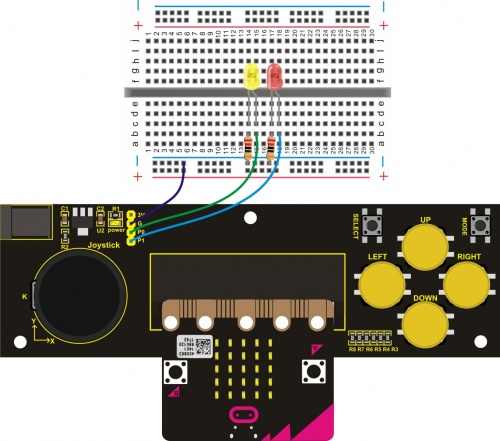
== Wiring Diagram == | |||
<br>[[File:KS0296.jpg|500px|frameless|thumb]]<br> | |||
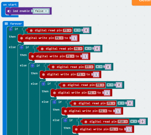
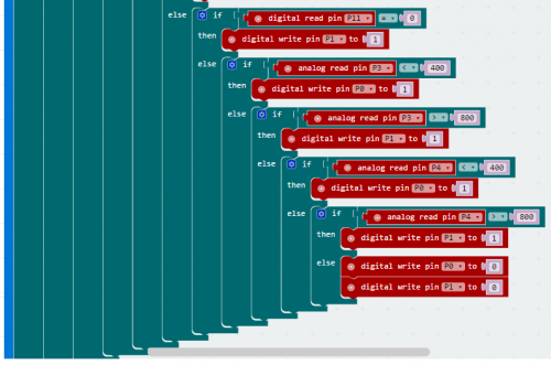
== Testing Program == | |||
<br>[[File:Ks0296 code 1.png|500px|frameless|thumb]]<br> | |||
<br>[[File:Ks0296 code 2.png|500px|frameless|thumb]]<br> | |||
== Testing Result == | |||
Insert the micro bit development board into Keyestudio joystick breakout board, powering up, 2 LEDs will display as below: | |||
1、Both joystick and buttons have no operation, 2 LEDs are off. | |||
2、Press down any buttons ( include joystick Z axis button), red LED is on; release the button, LED will be off. | |||
3、Joystick upward, red LED on; joystick downward, yellow LED on; joystick leftward, yellow LED on; joystick rightward, red LED on. | |||
== Resource == | == Resource == | ||
Revision as of 09:10, 23 April 2018
Keyestudio Joystick Breakout Board for micro:bit
Introduction
micro bit is an entry level development board designed by BBC for teens programming education. It supports the PXT graphical programming interface developed by Microsoft and can be used under Windows, MacOS, IOS, Android and many other operating systems without downloading the compiler.
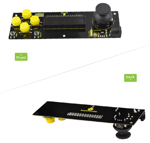
Keyestudio joystick breakout board for micro bit comes with AMS1117 chip. You can also connect external DC 4.75-12V to power for micro bit development board.
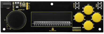
It can be used to simulate the mouse keyboard. On-board 3V、G、P0、P1 are connected to microbit board to imitate the serial port, thus connect the Bluetooth devices.
This board consists of 6 buttons and a joystick. Connect the button and joystick to micro bit pins.
Connect SELECT button to P7; MODE button to P6; UP button to P10; LEFT button to P11; RIGHT button to P9; DOWN button to P8. Connect joystick X axis to P4; Y axis to P3; Z axis to P5. You can control the external devices by reading the above interface states.
Parameters
- Input Voltage:DC 4.75-12V
Wiring Diagram
Testing Program
Testing Result
Insert the micro bit development board into Keyestudio joystick breakout board, powering up, 2 LEDs will display as below: 1、Both joystick and buttons have no operation, 2 LEDs are off. 2、Press down any buttons ( include joystick Z axis button), red LED is on; release the button, LED will be off. 3、Joystick upward, red LED on; joystick downward, yellow LED on; joystick leftward, yellow LED on; joystick rightward, red LED on.
Resource
Datasheet:
https://drive.google.com/open?id=1L9BGzfU3KXfl6fVnN_f3uJtbn28DLueM
Buy From
Official Website:
http://www.keyestudio.com/ks0296.html
From AliExpress: [1]
From Amazon: [2]
From Ebay: [3]
