Ks0064 keyestudio I2C 8x8 LED Matrix HT16K33: Difference between revisions
Keyestudio (talk | contribs) No edit summary |
Keyestudio (talk | contribs) No edit summary |
||
| Line 1: | Line 1: | ||
[[image:KS0336.png|thumb|600px|right|Keyestudio PIR Motion Sensor 3PCS]] | |||
==Introduction== | ==Introduction== | ||
A fun way to make a small display is to use an 8x8 matrix or a 4-digit 7-segment display. Matrices like these are 'multiplexed' - to control 64 LEDs you need 16 pins. That's a lot of pins, and there are driver chips like the MAX7219 that can control a matrix for you, but there's a lot of wiring to set up and they take up a ton of space. After all, wouldn't it be awesome if you could control a matrix without tons of wiring? That's where these lovely LED matrix backpacks come in. <br> | |||
The matrices use the constant-current drivers for ultra-bright, consistent color, 1/16 step display dimming, all via a simple I2C interface. These 1.2" matrix backpacks come with three address-selection jumpers so you can connect up to eight 1.2" 8x8's together (or a combination, such as four 1.2" 8x8's and four 7-segments, etc) on a single I2C bus. | |||
== Features == | |||
* 8 rows and 8 cols LED matrix | |||
* Driven by HT16K33 chip | |||
* Access to I2C communication pins | |||
* Occupy less IO ports of microcontrollers | |||
* Easy connection and available for more experiment extensions | |||
== | == Parameters== | ||
* Input | * Input voltage: 5V | ||
* Rated input frequency: 400KHZ | * Rated input frequency: 400KHZ | ||
* | * Input power: 2.5W | ||
* Input | * Input current: 500mA | ||
==Pinout== | |||
<br>[[ | <br>[[Image:KS0064.jpg|800px|frameless]]<br> | ||
==Wire it Up== | |||
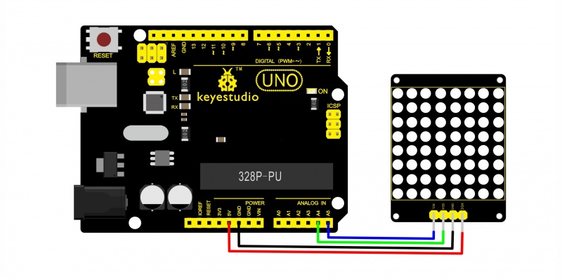
Connect the SCL pin to Analog A5, SDA pin to Analog A4 port; Connect VCC pin to 5V port, GND pin to GND. | |||
<br>[[Image:Ks0052.jpg|800px|frameless]]<br> | |||
==Sample Code== | ==Sample Code== | ||
Below is an example code, you can upload it to [http://wiki.keyestudio.com/index.php/Download_Arduino_IDE Arduino IDE]. | |||
*[http://wiki.keyestudio.com/index.php/Download_Arduino_IDE Download Arduino IDE ] | |||
*[http://wiki.keyestudio.com/index.php/Install_Arduino_Driver Install Arduino Driver ] | |||
*[http://wiki.keyestudio.com/index.php/Install_Arduino_Library Install Arduino Library ] | |||
<pre> | <pre> | ||
#include <Wire.h> | #include <Wire.h> | ||
| Line 52: | Line 71: | ||
</pre> | </pre> | ||
==Resources == | '''Note:''' before upload the code, you should place the library inside Arduino libraries. Or else fail to compile it. | ||
You can download the code libraries from the link below: <br> | |||
https://drive.google.com/open?id=1FUTIwsfGdxTXXgYDGxI7U2VoP0g3G-2L | |||
==Example Result== | |||
Done wiring and powered up, upload well the code to UNO board, you will see the dot matrix display the image shown below. | |||
<br>[[Image:KS0336-2.jpg|800px|frameless]]<br> | |||
==Packaging Included== | |||
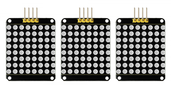
Keyestudio 8x8 Dot Matrix Module * 3PCS | |||
<br>[[Image:KS0336-3.jpg|800px|frameless]]<br> | |||
== Resources == | |||
* [https://drive.google.com/open?id=1R5K48jiZtJht6eXZuLmNJx5qKiSf5ug_ You can click here to download the datasheet] | |||
* [https://drive.google.com/open?id=1FUTIwsfGdxTXXgYDGxI7U2VoP0g3G-2L Click here to download the code libraries] | |||
* Video: http://www.keyestudio.com/wp/ks0064/ | |||
== Buy From == | |||
''' | * '''Official Website:''' http://www.keyestudio.com/ks0064.html | ||
https:// | * [https://www.amazon.com/dp/B0179AGI9K '''From Amazon'''] | ||
* [https://www.aliexpress.com/store/product/3PCS-Keyestudio-Red-color-common-cathode-I2C-8-8-LED-dot-Matrix-module-HT16K33-for-Arduino/1452162_32886174149.html?spm=2114.12010612.8148356.9.8cc65f38Ul6C7x '''From Aliexpress'''] | |||
Revision as of 17:29, 27 July 2018
Introduction
A fun way to make a small display is to use an 8x8 matrix or a 4-digit 7-segment display. Matrices like these are 'multiplexed' - to control 64 LEDs you need 16 pins. That's a lot of pins, and there are driver chips like the MAX7219 that can control a matrix for you, but there's a lot of wiring to set up and they take up a ton of space. After all, wouldn't it be awesome if you could control a matrix without tons of wiring? That's where these lovely LED matrix backpacks come in.
The matrices use the constant-current drivers for ultra-bright, consistent color, 1/16 step display dimming, all via a simple I2C interface. These 1.2" matrix backpacks come with three address-selection jumpers so you can connect up to eight 1.2" 8x8's together (or a combination, such as four 1.2" 8x8's and four 7-segments, etc) on a single I2C bus.
Features
- 8 rows and 8 cols LED matrix
- Driven by HT16K33 chip
- Access to I2C communication pins
- Occupy less IO ports of microcontrollers
- Easy connection and available for more experiment extensions
Parameters
- Input voltage: 5V
- Rated input frequency: 400KHZ
- Input power: 2.5W
- Input current: 500mA
Pinout
Wire it Up
Connect the SCL pin to Analog A5, SDA pin to Analog A4 port; Connect VCC pin to 5V port, GND pin to GND.
Sample Code
Below is an example code, you can upload it to Arduino IDE.
#include <Wire.h>
#include "Adafruit_LEDBackpack.h"
#include "Adafruit_GFX.h"
#ifndef _BV
#define _BV(bit) (1<<(bit))
#endif
Adafruit_LEDBackpack matrix = Adafruit_LEDBackpack();
uint8_t counter = 0;
void setup() {
  Serial.begin(9600);
  Serial.println("HT16K33 test");
  matrix.begin(0x70);  // pass in the address
}
void loop() {
  // paint one LED per row. The HT16K33 internal memory looks like
  // a 8x16 bit matrix (8 rows, 16 columns)
  for (uint8_t i=0; i<8; i++) {
// draw a diagonal row of pixels

    matrix.displaybuffer[i] = _BV((counter+i) % 16) | _BV((counter+i+8) % 16)  ;
  }
  // write the changes we just made to the display
  matrix.writeDisplay();
  delay(100);
 counter++;
  if (counter >= 16) counter = 0;
}
Note: before upload the code, you should place the library inside Arduino libraries. Or else fail to compile it.
You can download the code libraries from the link below:
https://drive.google.com/open?id=1FUTIwsfGdxTXXgYDGxI7U2VoP0g3G-2L
Example Result
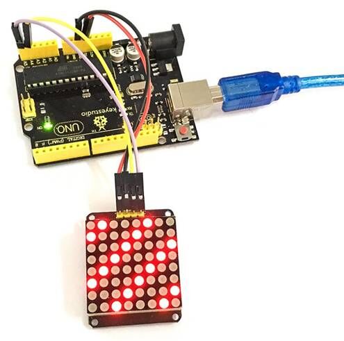
Done wiring and powered up, upload well the code to UNO board, you will see the dot matrix display the image shown below.
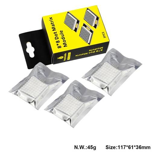
Packaging Included
Keyestudio 8x8 Dot Matrix Module * 3PCS
Resources
Buy From
- Official Website: http://www.keyestudio.com/ks0064.html
