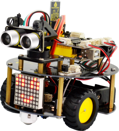
Ks0364 keyestudio Smart Little Turtle Robot V2.0: Difference between revisions
Keyestudio (talk | contribs) |
Keyestudio (talk | contribs) |
||
| (81 intermediate revisions by the same user not shown) | |||
| Line 243: | Line 243: | ||
| align="center" | 34 | | align="center" | 34 | ||
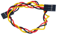
| align="center" | female-female jumper wire | | align="center" | female-female jumper wire | ||
<br> | |||
| align="center" | 1 | | align="center" | 1 | ||
| align="center" | <br>[[File:图片1 - jumper wire.png|300px|frameless|thumb]]<br> | | align="center" | <br>[[File:图片1 - jumper wire.png|300px|frameless|thumb]]<br> | ||
| Line 290: | Line 301: | ||
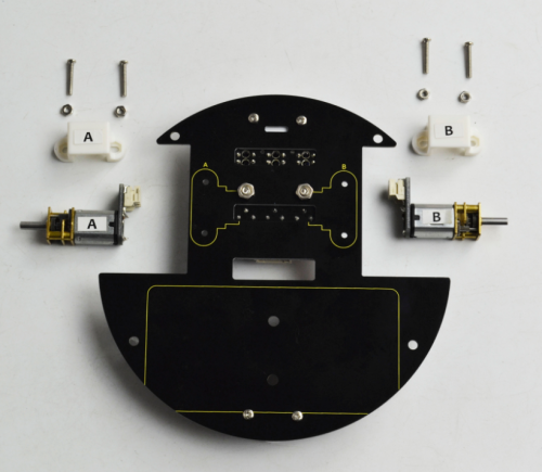
* Motor *2 | * Motor *2 | ||
<br>[[File:Ass 6.png|500px|frameless|thumb]]<br> | <br>[[File:Ass 6.png|500px|frameless|thumb]]<br> | ||
<span style=color:red> '''Note:''' Now you can check the label A,B on the motor panel.</span><br> | |||
<br>[[File:Motor A-B.png|500px|frameless|thumb]]<br> | |||
<br> | |||
Firstly place four M2 Nuts inside the holes of white N20 motor holders. You should get it as below. | Firstly place four M2 Nuts inside the holes of white N20 motor holders. You should get it as below. | ||
<br>[[File:Ass 7.png|500px|frameless|thumb]]<br> | <br>[[File:Ass 7.png|500px|frameless|thumb]]<br> | ||
| Line 300: | Line 316: | ||
Back view: | Back view: | ||
<br>[[File:Ass 11.png|500px|frameless|thumb]]<br> | <br>[[File:Ass 11.png|500px|frameless|thumb]]<br> | ||
<br> | <br> | ||
| Line 440: | Line 457: | ||
===Project 1: Getting Started with ARDUINO=== | ===Project 1: Getting Started with ARDUINO=== | ||
====1) | ==== 1)UNO Control Board ==== | ||
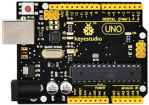
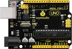
When it comes to using the UNO R3 as core of our robot, the UNO is the best board to get started with electronics and coding. If this is your first experience tinkering with the platform, the UNO is the most robust board you can start playing with. <br> | When it comes to using the UNO R3 as core of our robot, the UNO is the best board to get started with electronics and coding. If this is your first experience tinkering with the platform, the UNO is the most robust board you can start playing with. <br> | ||
[[image:UNO R3--.png|thumb|300px|right]] | [[image:UNO R3--.png|thumb|300px|right]] | ||
| Line 762: | Line 779: | ||
Furthermore, in the motor driving project below, it also involves the concept PWM. | Furthermore, in the motor driving project below, it also involves the concept PWM. | ||
<br> | <br> | ||
<br> | |||
====5) Light up LED Matrix==== | ====5) Light up LED Matrix==== | ||
'''Overview:''' | |||
In the previous project, we have simply tested the LED. Now we have added a new 8*8 Dot Matrix module to the turtle to show the robot states. Amazing display! | '''Overview:''' <br> | ||
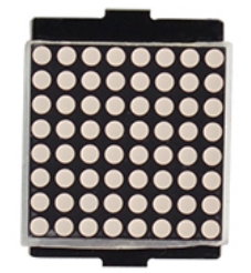
Do you know how is the cool advertising display made? It is exactly composed of these small LED matrix. If you want to make a similar display, this keyestudio 8*8 Dot Matrix | In the previous project, we have simply tested the LED. Now we have added a new 8*8 Dot Matrix module to the turtle to show the robot states. Amazing display! <br> | ||
Do you know how is the cool advertising display made? It is exactly composed of these small LED matrix. If you want to make a similar display, this [http://wiki.keyestudio.com/index.php/Ks0064_keyestudio_I2C_8x8_LED_Matrix_HT16K33 keyestudio 8*8 Dot Matrix module] will meet you need. <br> | |||
This tiny display has 64 LEDs packed into a 8*8 dot matrix. It integrated HT16K33as driver chip, so with this LED matrix module, you can control it through connecting the I2C communication interfaces ( A4-SDA ; A5-SCL). <br> | This tiny display has 64 LEDs packed into a 8*8 dot matrix. It integrated HT16K33as driver chip, so with this LED matrix module, you can control it through connecting the I2C communication interfaces ( A4-SDA ; A5-SCL). <br> | ||
It is great for displaying image/text or creating bizarre patterns, and is highly portable and convenient to use. Of course you can program it via IDE or via Mixly block. With just a few steps, you are ready to impress others!<br> | It is great for displaying image/text or creating bizarre patterns, and is highly portable and convenient to use. Of course you can program it via IDE or via Mixly block. With just a few steps, you are ready to impress others!<br> | ||
[[image:KS0364 - 图片2.png|thumb|500px|right]] | |||
<br> | |||
'''Hookup Guide:'''<br> | '''Hookup Guide:'''<br> | ||
Connect the LED matrix module to the pin header on the motor drive shield. Connect the SCL pin to pin A5, SDA pin to pin A4; Connect VCC pin to 5V, GND to ground. | Connect the LED matrix module to the pin header on the motor drive shield. Connect the SCL pin to pin A5, SDA pin to pin A4; Connect VCC pin to 5V, GND to ground. | ||
<br>[[File:Ks0364 - connection 3.png|700px|frameless|thumb]]<br> | |||
<br> | |||
'''Sample Code 3:''' <br> | '''Sample Code 3:''' <br> | ||
<pre> | |||
#include <Wire.h> | |||
#include "Adafruit_LEDBackpack.h" | |||
#include "Adafruit_GFX.h" | |||
Adafruit_LEDBackpack matrix = Adafruit_LEDBackpack(); | |||
void setup() { | |||
Serial.begin(9600); | |||
Serial.println("HT16K33 test"); | |||
matrix.begin(0x70); // pass in the address | |||
} | |||
'''Code To Note:'''<br> | void loop() | ||
In the code, it needs to call three libraries, that is Wire.h; Adafruit_LEDBackpack. | { | ||
/////////smile face/////////////// | |||
matrix.displaybuffer[0] = B00000011; | |||
matrix.displaybuffer[1] = B10000000; | |||
You can download the libraries from the link below:<br> | matrix.displaybuffer[2] = B00010011; | ||
https://drive.google.com/open?id=16ii-ZQTNK_Fn8KG81rhBw7JX1zQQ6nG6 | matrix.displaybuffer[3] = B00100000; | ||
matrix.displaybuffer[4] = B00100000; | |||
matrix.displaybuffer[5] = B00010011; | |||
matrix.displaybuffer[6] = B10000000; | |||
matrix.displaybuffer[7] = B00000011; | |||
matrix.writeDisplay(); | |||
} | |||
</pre> | |||
<br> | |||
<span style="color: red">'''Code To Note:''' </span> <br> | |||
In the code, it needs to call three libraries, that is ''Wire.h; Adafruit_LEDBackpack.h and Adafruit_GFX.h'' <br> | |||
''Wire.h'' is a built-in library of Arduino IDE, so not need to add it, but you should place the libraries folder [https://drive.google.com/open?id=1Fg4iyz1GAwLuM2Pid2zuK3o0rjIoWdiZ Adafruit_LEDBackpack.h ] and [https://drive.google.com/open?id=1EWay8sCtzs7juY7WWuEg3I3fRTOku-HT Adafruit_GFX.h ] inside the libraries directory of IDE. | |||
<br>[[File:KS0364 - 图片3.png|500px|frameless|thumb]]<br> | |||
<br> | |||
'''Note:''' place well the libraries folder, need to reopen the Arduino IDE again, and the libraries should be effective. <br> | |||
You can download the libraries from the link below: <br> | |||
https://drive.google.com/open?id=16ii-ZQTNK_Fn8KG81rhBw7JX1zQQ6nG6 | |||
<br> | |||
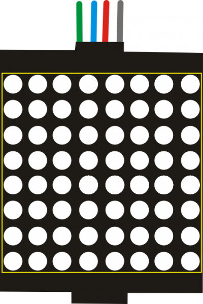
Place the LED matrix as the | Place the LED matrix as the right picture shown.<br> | ||
[[image:点阵.png|thumb|400px|right]] | |||
Note: the number 0 in the matrix.displaybuffer[0] represents the columns of LED. The number 0 is the first column, and the number 1 represents the second column. The rest can be done in the same manner. <br> | In the experiment, you can control the LED dot matrix display through the code '''matrix.displaybuffer[0] = B00000011''' | ||
B00000011 represents the on and off state of 8 LEDs in the cols. The number 0 represents off, while the number 1 represents on. <br> | <br> | ||
So matrix.displaybuffer[0] = B00000011 means that the first column, the LEDs in the row 1, 8, 7, 6, 5, 4 are set to off, the LEDs in the row 3 and 2 are on. <br> | <span style="color: red">'''Note:''' </span> the number '''0''' in the '''matrix.displaybuffer[0]''' represents the columns of LED. The number 0 is the first column, and the number 1 represents the second column. The rest can be done in the same manner. <br> | ||
'''B00000011''' represents the on and off state of 8 LEDs in the cols. The number 0 represents off, while the number 1 represents on. <br> | |||
So '''matrix.displaybuffer[0] = B00000011''' means that the first column, the LEDs in the row 1, 8, 7, 6, 5, 4 are set to off, the LEDs in the row 3 and 2 are on. <br> | |||
<br> | |||
'''What you should see?''' <br> | |||
Hookup well and upload the code to the board, you should see the keyestudio 8*8 Dot matrix show a smile face. | |||
<br>[[File:KS0364 - 图片4.png|600px|frameless|thumb]]<br> | |||
<br> | |||
===Project 2: Line Tracking Turtle=== | ===Project 2: Line Tracking Turtle=== | ||
====1) Principle and Application of Line Tracking Sensor==== | ====1) Principle and Application of Line Tracking Sensor==== | ||
'''Overview:''' | '''Overview:''' <br> | ||
The tracking sensor is actually an infrared sensor. The component used here is the TCRT5000 infrared tube. | The tracking sensor is actually an infrared sensor. The component used here is the TCRT5000 infrared tube. <br> | ||
Its working principle is to use the different reflectivity of infrared light to the color, then convert the strength of the reflected signal into a current signal. | Its working principle is to use the different reflectivity of infrared light to the color, then convert the strength of the reflected signal into a current signal. <br> | ||
During the process of detection, black is active at HIGH level, but white is active at LOW level. And detection height is 0-3 cm. | During the process of detection, black is active at HIGH level, but white is active at LOW level. And detection height is 0-3 cm. <br> | ||
The following figure is our keyestudio 3-channel line tracking module. We have integrated 3 sets of TCRT5000 infrared tube on a single board, which is more convenient for wiring and control. | The following figure is our keyestudio 3-channel line tracking module. We have integrated 3 sets of TCRT5000 infrared tube on a single board, which is more convenient for wiring and control. <br> | ||
By rotating the adjustable potentiometer on the sensor, it can adjust the detection sensitivity of the sensor. | By rotating the adjustable potentiometer on the sensor, it can adjust the detection sensitivity of the sensor. | ||
<br>[[File:KS0313 2-1-1.png|700px|frameless|thumb]]<br> | |||
'''TECH SPECS:''' | <br> | ||
Operating Voltage: 3.3-5V (DC) | '''TECH SPECS:''' <br> | ||
Interface: 5PIN | * Operating Voltage: 3.3-5V (DC) | ||
Output Signal: Digital signal | * Interface: 5PIN | ||
Detection Height: 0-3 cm | * Output Signal: Digital signal | ||
* Detection Height: 0-3 cm | |||
<br> | |||
'''Wiring Diagram:''' | '''Wiring Diagram:''' <br> | ||
Okay, next let’s do a simple test for this tracking module. | Okay, next let’s do a simple test for this tracking module. <br> | ||
Connect the line tracking module to the shield using connector wire. Then connect the LED module to the pin11 header on the shield. The connection diagram is shown as below. | Connect the line tracking module to the shield using connector wire. Then connect the LED module to the pin11 header on the shield. The connection diagram is shown as below. | ||
<br>[[File:Ks0364 - connection 4.png|700px|frameless|thumb]]<br> | |||
Wire it up well as the above diagram, then you can type the following test code. <br> | |||
<br> | |||
'''Test Code 4:''' | '''Test Code 4:''' | ||
<pre> | <pre> | ||
| Line 834: | Line 893: | ||
{ | { | ||
if( digitalRead(sensor1)==LOW) // read the state of sensor, if detect the white paper, it is at LOW level. | if( digitalRead(sensor1)==LOW) // read the state of sensor, if detect the white paper, it is at LOW level. | ||
{digitalWrite(ledPin, HIGH); //light an LED | {digitalWrite(ledPin, HIGH); // light an LED | ||
} | } | ||
else // or else | else // or else | ||
{ | { | ||
digitalWrite(ledPin, LOW); //turn off an LED | digitalWrite(ledPin, LOW); // turn off an LED | ||
} | } | ||
} | } | ||
</pre> | </pre> | ||
Test Code 5: | <br> | ||
So how do you think about that? It is really simple. For another two-channel, you can refer to the above code to finish the testing.<br> | |||
'''Test Code 5:''' | |||
<pre> | <pre> | ||
int sensor2 = 7; // define the pin of middle sensor as pin D7 | int sensor2 = 7; // define the pin of middle sensor as pin D7 | ||
int ledPin =11; //define LEDpin as Digital 11 | int ledPin =11; // define LEDpin as Digital 11 | ||
void setup() | void setup() | ||
{ | { | ||
pinMode(sensor2, INPUT); //define the sensor as INPUT | pinMode(sensor2, INPUT); // define the sensor as INPUT | ||
pinMode(ledPin,OUTPUT);//define LED as OUTPUT | pinMode(ledPin,OUTPUT); // define LED as OUTPUT | ||
} | } | ||
void loop() | void loop() | ||
{ | { | ||
if( digitalRead(sensor2)==LOW) //read the state of sensor, if detect the white paper, it is at LOW level. | if( digitalRead(sensor2)==LOW) // read the state of sensor, if detect the white paper, it is at LOW level. | ||
{digitalWrite(ledPin, HIGH); //light an LED | {digitalWrite(ledPin, HIGH); // light an LED | ||
} | } | ||
else //or else | else //or else | ||
{ | { | ||
digitalWrite(ledPin, LOW); //turn off an LED | digitalWrite(ledPin, LOW); // turn off an LED | ||
} | } | ||
} | } | ||
</pre> | </pre> | ||
<br> | |||
'''Test Code 6:''' | '''Test Code 6:''' | ||
<pre> | <pre> | ||
| Line 888: | Line 949: | ||
</pre> | </pre> | ||
<br> | |||
Upload well the code to the board, you should see that if the tracking sensor detects a white object, the LED module will light up. | Upload well the code to the board, you should see that if the tracking sensor detects a white object, the LED module will light up. | ||
<br> [[File:KS0313 2-1-4.png|800px|frameless|thumb]]<br> | |||
<br> | |||
In the section below, we are about to match the digital sensors with other modules to make interactive works. | |||
<br> | |||
<br> | |||
====2) Motor Driving and Speed Control==== | ====2) Motor Driving and Speed Control==== | ||
<br>[[File:Ks0313 Motor .jpg|500px|frameless|thumb]]<br> | |||
'''Overview:''' | '''Overview:''' <br> | ||
There are many ways to drive the motor. Our robot uses the most commonly used L298P solution. | There are many ways to drive the motor. Our robot uses the most commonly used L298P solution. <br> | ||
L298P is an excellent high-power motor driver IC produced by STMicroelectronics. It can directly drive DC motors, two-phase and four-phase stepping motors. | L298P is an excellent high-power motor driver IC produced by STMicroelectronics. It can directly drive DC motors, two-phase and four-phase stepping motors. <br> | ||
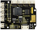
The driving current up to 2A, and output terminal of motor adopts eight high-speed Schottky diodes as protection. We have designed the motor driver shield based on the L298P circuit. | The driving current up to 2A, and output terminal of motor adopts eight high-speed Schottky diodes as protection. We have designed the motor driver shield based on the L298P circuit. <br> | ||
The stackable design can make it be plugged directly into the Arduino, reducing the technical difficulty of using and driving the motor. | The stackable design can make it be plugged directly into the Arduino, reducing the technical difficulty of using and driving the motor. | ||
When stack the driver shield onto UNO R3 board, after the BAT is powered on, press the POWER button lightly. The external power will be supplied to both the driver shield and UNO R3 board at the same time. | <br>[[File:KS0364 - 图片5.png|800px|frameless|thumb]]<br> | ||
In order to facilitate wiring, the driver shield comes with an anti-reverse interface. When connecting the motor, power supplyand sensor modules, you just need to plug incorrectly. | When stack the driver shield onto UNO R3 board, after the BAT is powered on, press the POWER button lightly. The external power will be supplied to both the driver shield and UNO R3 board at the same time. <br> | ||
The Bluetooth interface on the driver shield is fully compatible with keyestudio HC-06 Bluetooth module. When connecting, you just need to plug HC-06 Bluetooth module into the corresponding interface. | In order to facilitate wiring, the driver shield comes with an anti-reverse interface. When connecting the motor, power supplyand sensor modules, you just need to plug incorrectly. <br> | ||
At the same time, thedrive shield solders 2.54mm pin headers tolead outsome unused digital ports and analog ports, so that you can continue to add other sensors for experiments extension. | The Bluetooth interface on the driver shield is fully compatible with keyestudio HC-06 Bluetooth module. When connecting, you just need to plug HC-06 Bluetooth module into the corresponding interface. <br> | ||
At the same time, thedrive shield solders 2.54mm pin headers tolead outsome unused digital ports and analog ports, so that you can continue to add other sensors for experiments extension. <br> | |||
<br> | |||
'''Specifications:''' | '''Specifications:''' | ||
1. Logic part input voltage: 5V | * 1. Logic part input voltage: 5V | ||
2. Driving part input voltage: DC 7-12V | * 2. Driving part input voltage: DC 7-12V | ||
3. Logic part working current: <36mA | * 3. Logic part working current: <36mA | ||
4.Driving part working current: <2A | * 4.Driving part working current: <2A | ||
5. Maximum powerdissipation: 25W (T=75℃) | * 5. Maximum powerdissipation: 25W (T=75℃) | ||
6. Control signal input level: | * 6. Control signal input level: | ||
High level: 2.3V<Vin<5V | High level: 2.3V<Vin<5V <br> | ||
Low level: -0.3V<Vin<1.5V | Low level: -0.3V<Vin<1.5V | ||
7. Working temperature: -25℃~+130℃ | * 7. Working temperature: -25℃~+130℃ | ||
<br> | |||
'''Pinout Instructions:'''<br> | '''Pinout Instructions:'''<br> | ||
As the diagram shown below, you can get the detailed information of connectors on the motor drive shield.<br> | As the diagram shown below, you can get the detailed information of connectors on the motor drive shield.<br> | ||
<br>[[File:KS0313 2-2-2.png|800px|frameless|thumb]]<br> | <br>[[File:KS0313 2-2-2.png|800px|frameless|thumb]]<br> | ||
<br> | |||
'''Driving DC Motor:''' <br> | '''Driving DC Motor:''' <br> | ||
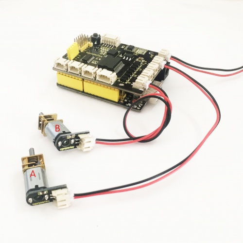
In the previous section, we have shown you the basic principle and parameters of L298P motor drive module. You can get the details of all interfaces on the board. So in the following, we will formally introduce how to drive the motor? First, you should connect well two motors to the shield, i.e. motor A and motor B shown as below. | In the previous section, we have shown you the basic principle and parameters of L298P motor drive module. You can get the details of all interfaces on the board. So in the following, we will formally introduce how to drive the motor? First, you should connect well two motors to the shield, i.e. motor A and motor B shown as below. | ||
<br>[[File: | <br>[[File:Ks0364 - connection 5.png|700px|frameless|thumb]]<br> | ||
<br> | |||
Well, next let’s create the sketch. <br> | Well, next let’s create the sketch. <br> | ||
The code logic of the | The code logic of the robot is nothing more than 5 kinds of movement modes, namely go forward, go backward, turn left, turn right and stop. So think about it. How could it implement those functions? <br> | ||
Simply, for example, both left and right motor of robot turn forward, so it is able to go forward. If both the left and right motor turn reverse, the robot will go backward. <br> | |||
It is much more easier to understand the motor turning, however, it would be a little bit complicated to work out the speed control of motor. | Besides, if the left motor turns forward but right motor turns reverse, the robot will turn right. If the right motor turns forward but left motor turns reverse, the robot will turn left. <br> | ||
As for the speed control of motor, it involves the PWM mode. So what is PWM? | So how to control the forward and backward of motor? Actually, you can easily achieve that by controlling the microcontroller pin for motor direction to be HIGH or LOW level. <br> | ||
<br> | |||
It is much more easier to understand the motor turning, however, it would be a little bit complicated to work out the speed control of motor. | |||
As for the speed control of motor, it involves the PWM mode mentioned in the previous section. So what is PWM? | |||
<br> | |||
PWM is the short for Pulse Width Modulation. PWM is a technique for getting analog results with digital means. Digital control is used to create a square wave (a signal switched between on and off) to control the analog output. The output voltage of Arduino Digital port only has LOW and HIGH level, corresponding to the output voltage of 0 Volts and 5 Volts. | |||
<br> | |||
Like the graphic shown below, the green lines represent a regular time period. This duration or period is the inverse of the PWM frequency. | |||
In other words, with Arduino's PWM frequency at about 500Hz, the green lines would measure 2 milliseconds each. <br> | |||
A call to analogWrite() is on a scale of 0-255, such that analogWrite(255) requests a 100% duty cycle (always on), and analogWrite(127) is a 50% duty cycle (on half the time) for example. <br> | |||
<br> [[Image:KS0313(4)-1.png|500px|frameless]] <br> | |||
<br> | |||
<br> | For example, we have marked the PWM pins that can be used for analog output on the UNO board. <br> | ||
The PWM pins are D3, D5, D6, D9, D10, and D11. | |||
For example | |||
<br>[[Image:KS0313(4).png|500px|frameless]]<br> | <br>[[Image:KS0313(4).png|500px|frameless]]<br> | ||
<br> | |||
The function called by the PWM is: '''analogWrite(pin, value)'''. <br> | |||
Note that the value is between 0 (always off) and 255 (always on). The speed of the motor is controlled actually by this value. The bigger the value is, the faster the speed is. Rather, the smaller the value is, the slower the speed it is until it stops. <br> | |||
In the following figure, look at the language logic for motor states: go forward, backward, turn left, turn right and stop. <br> | |||
'''M1''' and '''M2''' represent the motor’s direction control, that is, forward and backward rotation. <br> | |||
In the following figure, look at the language logic | '''E1''' and '''E2''' represent the speed control, and speed is set to 150. <br> | ||
{| width="80%" cellspacing="0" border="1" | {| width="80%" cellspacing="0" border="1" | ||
| Line 958: | Line 1,035: | ||
|- | |- | ||
| align="center" | | | align="center" | Forward | ||
| align="center" | 150 | | align="center" | 150 | ||
| align="center" | HIGH | | align="center" | HIGH | ||
| align="center" | Motor | | align="center" | Motor A goes forward | ||
| align="center" | 150 | | align="center" | 150 | ||
| align="center" | HIGH | | align="center" | HIGH | ||
| align="center" | Motor | | align="center" | Motor B goes forward | ||
|- | |- | ||
| align="center" | | | align="center" | Backward | ||
| align="center" | 150 | | align="center" | 150 | ||
| align="center" | LOW | | align="center" | LOW | ||
| align="center" | Motor | | align="center" | Motor A goes backward | ||
| align="center" | 150 | | align="center" | 150 | ||
| align="center" | LOW | | align="center" | LOW | ||
| align="center" | Motor | | align="center" | Motor B goes backward | ||
|- | |- | ||
| align="center" | | | align="center" | Left | ||
| align="center" | 150 | | align="center" | 150 | ||
| align="center" | LOW | | align="center" | LOW | ||
| align="center" | Motor | | align="center" | Motor A goes forward | ||
| align="center" | 150 | | align="center" | 150 | ||
| align="center" | | | align="center" | HIGH | ||
| align="center" | Motor | | align="center" | Motor B goes backward | ||
|- | |- | ||
| align="center" | | | align="center" | Right | ||
| align="center" | 150 | | align="center" | 150 | ||
| align="center" | HIGH | | align="center" | HIGH | ||
| align="center" | Motor | | align="center" | Motor A goes backward | ||
| align="center" | 150 | | align="center" | 150 | ||
| align="center" | LOW | | align="center" | LOW | ||
| align="center" | Motor | | align="center" | Motor B goes forward | ||
|- | |- | ||
| Line 997: | Line 1,074: | ||
| align="center" | 0 | | align="center" | 0 | ||
| align="center" | LOW | | align="center" | LOW | ||
| align="center" | Motor | | align="center" | Motor A stops | ||
| align="center" | 0 | | align="center" | 0 | ||
| align="center" | LOW | | align="center" | LOW | ||
| align="center" | Motor | | align="center" | Motor B stops | ||
|- | |- | ||
|} | |} | ||
<br> | |||
<br> | <br> | ||
'''Example Code 7: ''' <br> | '''Example Code 7: ''' <br> | ||
Okay, next we will start to write the example code. The part of Single line comment (//) is the explanation for the code. Based on that, you can understand it better. | Okay, next we will start to write the example code. The part of Single line comment (//) is the explanation for the code. Based on that, you can understand it better. | ||
<pre> | <pre> | ||
int E1 = 9; // set the speed pin of motor A as D9 | int E1 = 9; // set the speed pin of motor A as D9 | ||
| Line 1,012: | Line 1,091: | ||
int M1 = 2; // set the direction pin of motor A as D2 | int M1 = 2; // set the direction pin of motor A as D2 | ||
int M2 = 4; // set the direction pin of motor B as D4 | int M2 = 4; // set the direction pin of motor B as D4 | ||
void setup(void) | void setup(void) | ||
{ | { | ||
| Line 1,037: | Line 1,116: | ||
void turnL(void) // set the left turn | void turnL(void) // set the left turn | ||
{ | { | ||
digitalWrite(M1,LOW); // motor A turns reverse and the wheel will go backward | digitalWrite(M1,LOW); // motor A turns reverse and the wheel will go backward | ||
digitalWrite(M2, HIGH); // motor B turns forward and the wheel goes forward, the smart car will turn left. | digitalWrite(M2, HIGH); // motor B turns forward and the wheel goes forward, the smart car will turn left. | ||
analogWrite(E1,150); // speed of motor A | analogWrite(E1,150); // speed of motor A | ||
| Line 1,045: | Line 1,124: | ||
void turnR(void) // set the right turn | void turnR(void) // set the right turn | ||
{ | { | ||
digitalWrite(M1,HIGH); // motor A turns forward and the wheel will go forward | digitalWrite(M1,HIGH); // motor A turns forward and the wheel will go forward | ||
digitalWrite(M2,LOW); // motor B turns reverse and the wheel goes backward, the smart car will turn right. | digitalWrite(M2,LOW); // motor B turns reverse and the wheel goes backward, the smart car will turn right. | ||
analogWrite(E1,150); // speed of motor A | analogWrite(E1,150); // speed of motor A | ||
| Line 1,054: | Line 1,133: | ||
{ | { | ||
digitalWrite(M1,LOW); // motor A turns reverse | digitalWrite(M1,LOW); // motor A turns reverse | ||
digitalWrite(M2, LOW); // | digitalWrite(M2, LOW); // motor B turns reverse | ||
analogWrite(E1, 0); // speed of motor A, speed as zero, means stop | analogWrite(E1, 0); // speed of motor A, speed as zero, means stop | ||
analogWrite(E2, 0); // speed of motor B, speed as zero, means stop | analogWrite(E2, 0); // speed of motor B, speed as zero, means stop | ||
| Line 1,062: | Line 1,141: | ||
{ | { | ||
advance(); // go forward | advance(); // go forward | ||
delay(1000); //delay1S | delay(1000); // delay1S | ||
back(); //backward | back(); //backward | ||
delay(1000);//delay1S | delay(1000);// delay1S | ||
turnL(); //turn left | turnL(); //turn left | ||
delay(1000);//delay1S | delay(1000);//delay1S | ||
turnR(); //turn right | turnR(); //turn right | ||
delay(1000); //delay1S | delay(1000); //delay1S | ||
stopp(); // stop | stopp(); // stop | ||
| Line 1,075: | Line 1,154: | ||
</pre> | </pre> | ||
<br> | |||
'''Test Result:''' <br> | '''Test Result:''' <br> | ||
Stack well the drive shield onto UNO R3 board, and upload the above code to the board, then press down the POWER button, you should see the motor go forward for one second, backward one second, then turn left for one second, turn right for one second and stop one second, alternately repeating. | Stack well the drive shield onto UNO R3 board, and upload the above code to the board, then press down the POWER button, you should see the motor go forward for one second, backward one second, then turn left for one second, turn right for one second and stop one second, alternately repeating. | ||
<br>[[File:Motor 2.jpg| | <br>[[File:Motor 2.jpg|600px|frameless|thumb]]<br> | ||
<br> | |||
====3) Line Tracking Turtle==== | ====3) Line Tracking Turtle==== | ||
[[File:Ks0364 - line track .jpg|500px|thumb|right]] | |||
'''Project Principle:'''<br> | '''Project Overview:''' <br> | ||
Using the characteristic that black has low reflectivity to light. When flat surface is not black, the infrared light transmitted by the sensor will be reflected back mostly, so the sensor outputs low level 0.When the flat surface has a black line and the sensor is above the black line, the reflected infrared light is very less due to the weak reflectivity of black, so it does not reach | In the previous sections, you have learned the principles and applications of both tracking module and the motor drive shield. After master that knowledge, let’s combine these two modules to make the turtle with line tracking function. <br> | ||
Use the main control board to determine whether the output end of sensor is 0 or 1, finally detect the black line.The main control board will control the turning direction of | So first what does line tracking mean? It refers to following the line trajectory. For instance, the smart robot will always follow or track the black line. <br> | ||
The principle is using the tracking sensor to detect the black track on the pavement, and detection signal will feed back to ARDUINO main control board. Then main control board will analyze and judge the collected signals to control and drive the motor in time, thus can adjust the turning direction of turtle robot. <br> | |||
That is why the turtle robot can automatically follow the black track, achieving the automatic line tracking function. <br> | |||
This technology has been applied to many areas such as driverless vehicles, unmanned factories, warehouses, and service robots. | |||
<br> | |||
'''Project Principle:''' <br> | |||
Using the characteristic that black has low reflectivity to light. <br> | |||
When flat surface is not black, the infrared light transmitted by the sensor will be reflected back mostly, so the sensor outputs low level 0.<br> | |||
When the flat surface has a black line and the sensor is above the black line, the reflected infrared light is very less due to the weak reflectivity of black, so it does not reach the action level and sensor outputs high level 1. <br> | |||
Use the main control board to determine whether the output end of sensor is 0 or 1, finally detect the black line. The main control board will control the turning direction of motor according to the received signal, so finally can control the movement of smart car. This is a simple line tracking robot. | |||
<br> | |||
'''Wiring Diagram:'''<br> | '''Wiring Diagram:'''<br> | ||
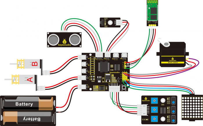
Connect the tracking sensor, two motors and battery pack to the motor drive shield as follows. | Connect the tracking sensor, two motors and battery pack to the motor drive shield as follows. | ||
<br>[[File: | <br>[[File:Ks0364 - connection 6.png|800px|frameless|thumb]]<br> | ||
<br> | |||
'''Example Code 8:''' <br> | '''Example Code 8:''' <br> | ||
Wire it up well as the above diagram. Okay, let’s move on to write the test code. Think about the logic | Wire it up well as the above diagram. Okay, let’s move on to write the test code. Think about the code logic. <br> | ||
There are two kinds of tracking sensor’s states as follows:<br> | There are two kinds of tracking sensor’s states as follows: <br> | ||
1. The middle tracking sensor detects a black line, if the sensor on the left side detects a white line, while the sensor on the right side detects a black line, the smart car will turn right. On the contrary, if the sensor on the right detects a white line, but the left one detects a black line, the smart car will turn left. If both sides detect a white line or a black line, | 1.The middle tracking sensor detects a black line, if the sensor on the left side detects a white line, while the sensor on the right side detects a black line, the smart car will turn right. <br> | ||
2. The middle tracking sensor does not detect a black line, if the sensor on the left side detects a white line, while the sensor on the right side detects a black line, the smart car will turn right. On the contrary, if the sensor on the right detects a white line, but the left one detects a black line, the smart car will turn left. If three sensors all detect a white line, | On the contrary, if the sensor on the right detects a white line, but the left one detects a black line, the smart car will turn left. If both sides detect a white line or a black line, it will go forward. <br> | ||
<br> | |||
2.The middle tracking sensor does not detect a black line, if the sensor on the left side detects a white line, while the sensor on the right side detects a black line, the smart car will turn right. <br> | |||
On the contrary, if the sensor on the right detects a white line, but the left one detects a black line, the smart car will turn left. If three sensors all detect a white line, it will stop. <br> | |||
<br> | |||
Well, figure out the logic, then combine the example code of motor driving mentioned in the above section, you can have a try to write out the logic of line tracking. <br> | |||
<pre> | |||
#define INT_A 2 // define the left motor direction pin D2 | |||
#define INT_B 4 // define the right motor direction pin D4 | |||
#define left_A 9 // define the left motor speed(PWM)pin D9 | |||
#define right_B 5 // define the right motor speed(PWM)D5 | |||
const int S1 = 8; // S1 right tracking sensor control pin to D8 | |||
const int S2 = 7; // S2 middle tracking sensor control pin to D7 | |||
const int S3 = 6; // S3 left tracking sensor control pin to D6 | |||
int s1,s2,s3; //define three variables, separately receive the digital value read by 3-channel tracking sensor (0 or 1) | |||
void setup() | |||
{ | |||
Serial.begin(9600); //set the monitor baud rate to 9600 | |||
delay(100); //delay 100ms | |||
pinMode(INT_A,OUTPUT); // set the motor control pin as OUTPUT | |||
pinMode(INT_B,OUTPUT); | |||
pinMode(left_A,OUTPUT); | |||
pinMode(right_B,OUTPUT); | |||
} | |||
void loop() | |||
{ | { | ||
s1 = digitalRead(S1); //assign the digital value read from pin S1,S2,S3 to s1,s2,s3 | |||
s2 = digitalRead(S2); | |||
s3 = digitalRead(S3); | |||
if(s2==1) //if s2 pin detects a black line | |||
{ | |||
if(s3==1 && s1==0) //if s3 pin detects a black line but s1 doesn’t | |||
{ | |||
left(); // turn left | |||
} | |||
else if(s3==0 && s1==1) //if s3 does not detect a black line, but s1 detects it. | |||
{ | |||
right(); //turn right | |||
} | |||
else //other situations | |||
{ | |||
front(); // go forward | |||
} | |||
} | |||
else //s2 does not detect a black line | |||
{ | |||
if(s3==1&&s1==0) //if s3 detects a black line | |||
{ | |||
left(); //turn left | |||
} | |||
else if(s3==0&&s1==1) //s1 detects a black line | |||
{ | |||
right(); // turn right | |||
} | |||
else // none detect black line | |||
{ | |||
Stop(); // stop | |||
} | |||
} | |||
} | } | ||
void | // forward | ||
void front() | |||
{ | { | ||
digitalWrite( | digitalWrite(INT_A,LOW); // control the left motor turn forward | ||
digitalWrite( | digitalWrite(INT_B,LOW); // control the right motor turn forward | ||
analogWrite( | analogWrite(left_A,200); // set the motor speed(PWM=200) | ||
analogWrite( | analogWrite(right_B,200); | ||
} | |||
void back( | //backward | ||
void back() | |||
{ | { | ||
digitalWrite(INT_A,HIGH); // control the left motor turn backward | |||
digitalWrite(INT_B,HIGH); // control the right motor turn backward | |||
analogWrite(left_A,200); | |||
analogWrite(right_B,200); | |||
} | |||
void | //turn left | ||
void left() | |||
{ | { | ||
digitalWrite(INT_A,HIGH); // control the left motor turn backward | |||
digitalWrite(INT_B,LOW); // control the right motor turn forward | |||
analogWrite(left_A,100); // motors speed(PWM为100) | |||
analogWrite(right_B,100); | |||
} | } | ||
void | // turn right | ||
void right() | |||
{ | { | ||
digitalWrite(INT_A,LOW); // control the left motor turn forward | |||
digitalWrite(INT_B,HIGH); // control the right motor turn backward | |||
analogWrite(left_A,100); | |||
analogWrite(right_B,100); | |||
} | } | ||
void | // stop | ||
void Stop() | |||
{ | { | ||
digitalWrite(INT_A,LOW); | |||
digitalWrite(INT_B,LOW); | |||
analogWrite(left_A,0); // both side PWM is 0 | |||
analogWrite(right_B,0); | |||
} | } | ||
</pre> | |||
<br> | <br> | ||
'''Example Picture: '''<br> | '''Example Picture: '''<br> | ||
<br>[[File:Line track motor.jpg| | <br>[[File:Line track motor.jpg|500px|frameless|thumb]]<br> | ||
<br> | |||
Upload well the above code to the main board, then press down the POWER button on the motor drive shield. If draw a black line on the ground, you should see that the smart car will track the black line. | Upload well the above code to the main board, then press down the POWER button on the motor drive shield. If draw a black line on the ground, you should see that the smart car will track the black line. | ||
<br>[[File: | <br>[[File:Ks0364 - line track .jpg|500px|frameless|thumb]]<br> | ||
<br> | |||
===Project 3: Turtle Robot Avoiding Obstacles=== | ===Project 3: Turtle Robot Avoiding Obstacles=== | ||
<br> | |||
====1) Principle and Application of Ultrasonic Module==== | ====1) Principle and Application of Ultrasonic Module==== | ||
[[File:KS0313 3-2-1.png|600px|thumb|right]] | |||
'''Description:'''<br> | '''Description:''' <br> | ||
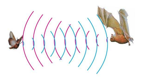
There is an animal called bat in nature. The | There is an animal called bat in nature. The bats can fly at night, not depend on its eyes, but on its ears and vocal organs. When the bat flies, it will emit a scream, an ultrasonic signal that humans cannot hear because of its high audio frequency. If these ultrasonic signals hit other objects on the flight path, they will be reflected back immediately. After receive the returned information, the bats complete the whole process of listening, seeing, calculating and bypassing obstacles during the flutter. <br> | ||
The principle of the ultrasonic rangefinder module is as the same as the above principle. The ultrasonic module will emit the ultrasonic waves after trigger signal. When the ultrasonic waves encounter the object and are reflected back, the module outputs an echo signal, so it can determine the distance of object from the time difference between trigger signal and echo signal. <br> | <br> | ||
Ultrasonic sensor has a wide range of sensitivity, no blind area, and no interference with obstacles. | The principle of the ultrasonic rangefinder module is as the same as the above principle. <br> | ||
As the following picture shown, it is our keyestudio ultrasonic module. You can see it has two somethings like eyes. One is transmitting end, the other is receiving end. | The ultrasonic module will emit the ultrasonic waves after trigger signal. When the ultrasonic waves encounter the object and are reflected back, the module outputs an echo signal, so it can determine the distance of object from the time difference between trigger signal and echo signal. <br> | ||
Ultrasonic sensor has a wide range of sensitivity, no blind area, and no interference with obstacles. | |||
<br> | |||
As the following picture shown, it is our keyestudio ultrasonic module. You can see it has two somethings like eyes. One is transmitting end, the other is receiving end. <br> | |||
<br>[[File:KS0313 3-2-2.png|800px|frameless|thumb]] [[File:KS0313 3-2-3.png|800px|frameless|thumb]]<br> | <br>[[File:KS0313 3-2-2.png|800px|frameless|thumb]] [[File:KS0313 3-2-3.png|800px|frameless|thumb]]<br> | ||
<br> | |||
'''TECH SPECS:'''<br> | '''TECH SPECS:'''<br> | ||
*Operating Voltage: 5V(DC)<br> | *Operating Voltage: 5V(DC)<br> | ||
*Operating Current: 15mA<br> | *Operating Current: 15mA <br> | ||
*Operating Frequency: 40khz<br> | *Operating Frequency: 40khz <br> | ||
*Maximum Detection Distance: 3-5m<br> | *Maximum Detection Distance: 3-5m <br> | ||
*Minimum Detection Distance: 3-4cm<br> | *Minimum Detection Distance: 3-4cm <br> | ||
*Sensing Angle: less than 15 degrees<br> | *Sensing Angle: less than 15 degrees <br> | ||
''' | <br> | ||
'''Hookup Guide:'''<br> | |||
Connect the ultrasonic module to the shield. Shown as below.<br> | Connect the ultrasonic module to the shield. Shown as below.<br> | ||
[[File: | [[File:Ks0364 - connection 7.png|700px|frameless|thumb]]<br> | ||
<br> | |||
'''【Notice:】'''<br> | '''【Notice:】'''<br> | ||
1.Must first connect the ultrasonic module and then power up. Or connect the ground first.<br> | 1.Must first connect the ultrasonic module and then power up. Or connect the ground first.<br> | ||
| Line 1,220: | Line 1,347: | ||
(2) The module automatically sends eight square waves of 40khz to automatically detect whether there is a signal return back;<br> | (2) The module automatically sends eight square waves of 40khz to automatically detect whether there is a signal return back;<br> | ||
(3) There is a signal return, through the IO output a High level, and the duration period of High level is the time of Ultrasonic wave from emission to return. <br> | (3) There is a signal return, through the IO output a High level, and the duration period of High level is the time of Ultrasonic wave from emission to return. <br> | ||
Test distance = (High level time * speed of sound (340M/S))/2 | '''Test distance = (High level time * speed of sound (340M/S))/2 ''' <br> | ||
Then you can get the formula: detection distance = (High level time/58) (cm) | Then you can get the formula: '''detection distance = (High level time/58)(cm)''' <br> | ||
<br> | |||
'''Example Code 9: '''<br> | '''Example Code 9: '''<br> | ||
<pre> | <pre> | ||
int pinTrip=12;// connect the SR04 Trip , give more than 10us High level | int pinTrip=12;// connect the SR04 Trip , give more than 10us High level | ||
| Line 1,252: | Line 1,379: | ||
</pre> | </pre> | ||
<br> | |||
'''Test Result:''' <br> | '''Test Result:''' <br> | ||
Stack well the shield on UNO R3 board, and upload well the above code, then open the serial monitor of Arduino IDE, set the baud rate | Stack well the shield on UNO R3 board, and upload well the above code, then open the serial monitor of Arduino IDE, set the baud rate to 9600. | ||
[[File:KS0313 3-2-5.png| | When ultrasonic sensor detects an obstacle ahead, on the monitor you should see the distance measured between obstacle and sensor. Shown below. | ||
<br>[[File:KS0313 3-2-5.png|600px|frameless|thumb]] [[File:KS0313 3-2-6.png|600px|frameless|thumb]]<br> | |||
<br> | <br> | ||
==== 2) Micro Servo Control ==== | |||
==== | <br>[[File:Ks0194- servo.png|400px|frameless|thumb]]<br> | ||
<br>[[File:Ks0194- servo.png| | |||
'''Description:'''<br> | '''Description:'''<br> | ||
Servo motor is a position control rotary actuator. It mainly consists of housing, circuit board, core-less motor, gear and position sensor.<br> | |||
Included with your servo motor you will find a variety of white motor mounts that connect to the shaft of your servo. You may choose to attach any mount you wish for the circuit. It will serve as a visual aid, making it easier to see the servo spin.<br> | Included with your servo motor you will find a variety of white motor mounts that connect to the shaft of your servo. You may choose to attach any mount you wish for the circuit. It will serve as a visual aid, making it easier to see the servo spin. <br> | ||
<br> | |||
'''Working principle:''' <br> | '''Working principle:''' <br> | ||
The receiver or MCU outputs a signal to the servo motor. The motor has a built-in reference circuit that gives out reference signal, cycle of 20ms and width of 1.5ms. The motor compares the acquired DC bias voltage to the voltage of potentiometer and outputs a voltage difference. | |||
<br> | |||
Servo motors come with many specifications. But all of them have three connection wires, distinguished by brown, red, orange color (different brand may have different color). Brown one is for GND, red one for power positive, orange one for signal. <br> | |||
Servo | |||
<br>[[File:ks0194-2.png|600px|frameless|thumb]]<br> | <br>[[File:ks0194-2.png|600px|frameless|thumb]]<br> | ||
When you send the right signal through the signal wire, the servo will move to a specific angle and stay there. Common servos rotate over a range of about 0° to 180°. The signal that is sent is a PWM signal. | |||
<br>[[File:180度舵机.png|600px|frameless|thumb]]<br> | <br>[[File:180度舵机.png|600px|frameless|thumb]]<br> | ||
<br> | |||
The rotation angle of servo motor is controlled by regulating the duty cycle of PWM(Pulse-Width Modulation) signal. The standard cycle of the PWM signal is 20ms (50Hz). Theoretically, the width is distributed between 1ms-2ms, but in fact, it's between 0.5ms-2.5ms. The width corresponds the rotation angle from 0° to 180°. <br> | |||
<br> | <br> | ||
'''Parameters'''<br> | '''Parameters:'''<br> | ||
*Operating voltage: DC 4.8V〜6V | *Operating voltage: DC 4.8V〜6V | ||
*Angle range: about 180°(in 500→2500μsec) | *Angle range: about 180°(in 500→2500μsec) | ||
| Line 1,294: | Line 1,420: | ||
*Weight: 9± 1 g (without servo mounts) | *Weight: 9± 1 g (without servo mounts) | ||
'''Hookup Guide: '''<br> | <br> | ||
'''Hookup Guide: ''' <br> | |||
Ready to start hooking everything up? Check out the connection diagram below. Connect the black servo to the shield. Brown wire is for GND, red one for 5V pin, orange one for signal pin. | Ready to start hooking everything up? Check out the connection diagram below. Connect the black servo to the shield. Brown wire is for GND, red one for 5V pin, orange one for signal pin. | ||
<br>[[File:Ks0364 - connection 8.png|700px|frameless|thumb]]<br> | |||
You can check out the test code for the servo below. | <br> | ||
You can check out the test code for the servo below.<br> | |||
'''Code 10:''' <br> | '''Code 10:''' <br> | ||
<pre> | |||
int servopin=3;// define the digital 9 is connected to servo signal line | |||
int myangle;// define the angle variable | |||
int pulsewidth;// define the pulsewidth variable | |||
int val; | |||
void setup() | |||
{ | |||
pinMode(servopin,OUTPUT);// set the servo interface as OUTPUT | |||
Serial.begin(9600);// connect to serial port, baud rate to 9600 | |||
Serial.println("servo=o_seral_simple ready" ); | |||
servopulse(servopin,90);// call the pulse function, make the servo rotate to 90degree | |||
} | |||
void loop() | |||
{ | |||
servopulse(servopin,90);// call the pulse function, make the servo rotate to 90degree | |||
} | |||
void servopulse(int servopin,int myangle)// define a pulse function | |||
{ | |||
pulsewidth=(myangle*11)+500;// convert the angle into pulse width of 500-2480 | |||
digitalWrite(servopin,HIGH);// set the servo pin to HIGH | |||
delayMicroseconds(pulsewidth);// delay the microseconds of pulsewidth | |||
digitalWrite(servopin,LOW);// set the servo pin to LOW | |||
delay(20-pulsewidth/1000); | |||
} | |||
</pre> | |||
<br> | |||
'''Test Result:''' <br> | '''Test Result:''' <br> | ||
Wire it up and upload well the code, press down the reset button on the shield, micro servo will rotate to the angle of | Wire it up and upload well the code, press down the reset button on the shield, micro servo will rotate to the angle of 90 degrees. | ||
<br>[[File:KS0364 - 图片6.png|600px|frameless|thumb]]<br> | |||
<br> | |||
The smart robot with UNO R3 as the controlling core, makes use of ultrasonic module and micro servo of 180 degrees to detect the obstacles, and the detection signal will feed back to the control board. | ==== 3) Turtle Robot Avoiding Obstacles ==== | ||
'''Description:''' <br> | |||
It is rather not suitable for human to work in some relatively harsh environments. At this moment, if we have a robot that can shuttle freely in such environments, then how good should it be! <br> | |||
Based on this original intention, our team develop the robot that be able to automatically avoid an obstacle when running on complicated terrain. <br> | |||
[[File:Ks0364 avoid.jpg|500px|thumb|right ]] | |||
This project is a simple and automatic obstacle avoidance system based on Arduino control board. <br> | |||
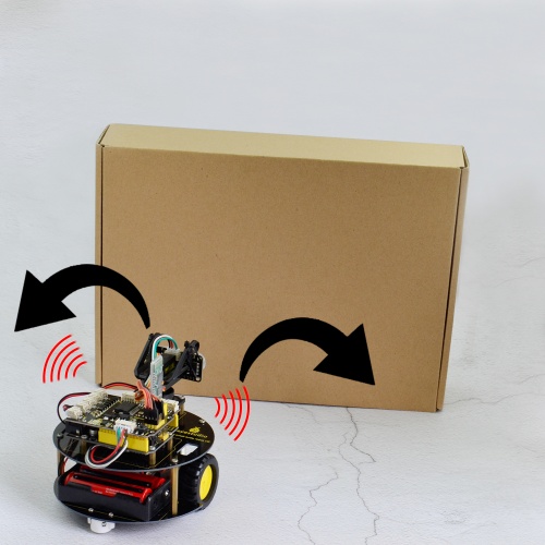
The smart robot with UNO R3 as the controlling core, makes use of ultrasonic module and micro servo of 180 degrees to detect the obstacles, and the detection signal will feed back to the control board. <br> | |||
Arduino main board will then analyze and judge the collected signals to control the motordriving in time. Finally control the smart car automatically avoid an obstacle ahead to run forward smoothly. <br> | |||
<br> | |||
'''Project Principle:'''<br> | '''Project Principle:'''<br> | ||
1. Use the ultrasonic module to detect the distance between the robot and obstacle ahead. | * 1. Use the ultrasonic module to detect the distance between the robot and obstacle ahead. <br> | ||
2. When the measured distance between ultrasonic sensor and obstacle ahead is less than 15cm, smart robot will stop for 100ms. The ultrasonic will make use of servo to turn left in 90 degrees, and stop for 100ms to detect the obstacle distance on the left. Then use the servo to turn right in 180 degrees, stop to detect the obstacle distance on the right. | * 2. When the measured distance between ultrasonic sensor and obstacle ahead is less than 15cm, smart robot will stop for 100ms. The ultrasonic will make use of servo to turn left in 90 degrees, and stop for 100ms to detect the obstacle distance on the left. Then use the servo to turn right in 180 degrees, stop to detect the obstacle distance on the right. <br> | ||
3. If the distance measured at the left side is greater than that of the right side, ultrasonic sensor will first turn to the front, turtle robot turns left in 90 degrees and then goes forward. | * 3. If the distance measured at the left side is greater than that of the right side, ultrasonic sensor will first turn to the front, turtle robot turns left in 90 degrees and then goes forward. | ||
Otherwise, turtle robot will turn right in 90 degrees and then go forward. | * Otherwise, turtle robot will turn right in 90 degrees and then go forward. <br> | ||
4. Arduino control board will control the motor’s rotating direction and servo angle according to the distance value measured by ultrasonic sensor between robot and obstacle. | * 4. Arduino control board will control the motor’s rotating direction and servo angle according to the distance value measured by ultrasonic sensor between robot and obstacle. | ||
<br> | |||
'''Wiring Diagram:'''<br> | '''Wiring Diagram:'''<br> | ||
Firstly you can follow the connection diagram below. | Firstly you can follow the connection diagram below. | ||
Connect the ultrasonic module, micro servo and two motors to the drive shield. | Connect the ultrasonic module, micro servo and two motors to the drive shield. | ||
<br>[[File:Ks0364 - connection 9.png|700px|frameless|thumb]]<br> | |||
<br> | |||
'''Code 11:''' <br> | '''Code 11:''' <br> | ||
Let’s move on to an example code for the obstacle avoidance robot. You can see the code reference below: | Let’s move on to an example code for the obstacle avoidance robot. You can see the code reference below: | ||
<pre> | |||
#define INT_A 2 // control the left motor direction pin to D2 | |||
#define INT_B 4 // control the right motor direction pin to D4 | |||
#define left_A 9 // define the left motor speed as pin D9 | |||
#define right_B 5 // define the right motor speed as pin D5 | |||
// Ultrasonic | |||
int servopin=3;// digital 3 is connected to servo signal pin | |||
int myangle;// define the angle | |||
int pulsewidth;// define the pulsewidth | |||
#include <SR04.h> // add the ultrasonic libraries | |||
#define TRIG_PIN 12 // define the pin ting of ultrasonic as D12 | |||
#define ECHO_PIN 13 //define the pin echo of ultrasonic as D13 | |||
SR04 sr04 = SR04(ECHO_PIN,TRIG_PIN); // build the ultrasonic object to control the ultrasonic | |||
long a,a1,a2; // used to receive the distance measured by ultrasonic | |||
void setup() | |||
{ | |||
Serial.begin(9600); // set the monitor baud rate to 9600 | |||
delay(100); // delay 100ms | |||
pinMode(INT_A,OUTPUT); // set the motor control pin as OUTPUT | |||
pinMode(INT_B,OUTPUT); | |||
pinMode(left_A,OUTPUT); | |||
pinMode(right_B,OUTPUT); | |||
pinMode(servopin,OUTPUT);// set the servo pin as OUTPUT | |||
servopulse(servopin,90); // call the pulse function, make the ultrasonic keep front. | |||
} | |||
void loop() | |||
{ | |||
a=sr04.Distance(); // assign the front distance measured by ultrasonic to a | |||
Serial.print(a); // print a value on the monitor | |||
Serial.println("cm"); // print cm and line wrap | |||
delay(100); // delay | |||
if(a<15) // whether the distance a is less than 15cm, if yes, then perform the program in the brace. | |||
{ | |||
Stop(); // car stops | |||
delay(100); // delay 100ms | |||
servopulse(servopin,160);// call the pulse function to make ultrasonic sensor turn left in 90 degrees | |||
a1=sr04.Distance(); // assign the left obstacle distance measured by ultrasonic to a1 | |||
Serial.print("a1 = "); // print out the a1 = on the serial monitor | |||
Serial.print(a1); //print a1 value | |||
Serial.println("cm"); // print cm and line wrap | |||
delay(100); // delay 100ms | |||
servopulse(servopin,20);// call the pulse function to make ultrasonic sensor turn right in 90 degrees | |||
a2=sr04.Distance(); // assign the right obstacle distance measured by ultrasonic to a2 | |||
Serial.print("a2 = "); | |||
Serial.print(a2); | |||
Serial.println("cm"); | |||
delay(100); | |||
if(a1>a2) // whether a1 is greater than a2(whether left distance is greater than that measured on the right side.) | |||
{ | |||
servopulse(servopin,90);// call the pulse function, make the ultrasonic keep front. | |||
left(); //turn left | |||
delay(370); // delay370ms,the time for car to turn left in 90 degrees as much as possible. | |||
front(); // go front | |||
} | |||
else // if a1<a2 | |||
{ | |||
servopulse(servopin,90); // call the pulse function, make the ultrasonic keep front. | |||
right(); // turn right | |||
delay(370); // delay 370ms,the time for car to turn right in 90 degrees as much as possible. | |||
front(); // the car goes forward | |||
} | |||
} | |||
else // if a>15cm | |||
{ | |||
front(); //the car goes forward | |||
} | |||
} | |||
// forward | |||
void front() | |||
{ | |||
digitalWrite(INT_A,LOW); // control the left motor turn forward | |||
digitalWrite(INT_B,LOW); // control the right motor turn forward | |||
analogWrite(left_A,200); // set the motor speed(PWM=200) | |||
analogWrite(right_B,200); | |||
} | |||
// backward | |||
void back() | |||
{ | |||
digitalWrite(INT_A,HIGH); // control the left motor turn backward | |||
digitalWrite(INT_B,HIGH); //control the right motor turn backward | |||
analogWrite(left_A,200); | |||
analogWrite(right_B,200); | |||
} | |||
// turn left | |||
void left() | |||
{ | |||
digitalWrite(INT_A,HIGH); //control the left motor turn backward | |||
digitalWrite(INT_B,LOW); // control the right motor turn forward | |||
analogWrite(left_A,150); // two motors’ speed(PWM为150) | |||
analogWrite(right_B,150); | |||
} | |||
// turn right | |||
void right() | |||
{ | |||
digitalWrite(INT_A,LOW); // control the left motor turn forward | |||
digitalWrite(INT_B,HIGH); // control the right motor turn backward | |||
analogWrite(left_A,150); | |||
analogWrite(right_B,150); | |||
} | |||
// stop | |||
void Stop() | |||
{ | |||
digitalWrite(INT_A,LOW); | |||
digitalWrite(INT_B,LOW); | |||
analogWrite(left_A,0); // PWM of both left and right is 0 | |||
analogWrite(right_B,0); | |||
} | |||
// servo | |||
void servopulse(int servopin,int myangle)// define a pulse function | |||
{ | |||
for(int i=0;i<50;i++) | |||
{ | |||
pulsewidth=(myangle*11)+500;// convert the angle into the pulsewidth of 500-2480 | |||
digitalWrite(servopin,HIGH);// servo pin to HIGH | |||
delayMicroseconds(pulsewidth);// delay the microseconds of pulsewidth | |||
digitalWrite(servopin,LOW);// servo pin to LOW | |||
delay(20-pulsewidth/1000); // delay the rest circle time to LOW level(20ms circle ) | |||
} | |||
} | |||
</pre> | |||
<br> | |||
'''Test Result:''' <br> | '''Test Result:''' <br> | ||
Upload the above code to the control board, and stack well the drive shield onto control board, then press lightly down the POWER button on the drive shield. | Upload the above code to the control board, and stack well the drive shield onto control board, then press lightly down the POWER button on the drive shield. <br> | ||
When detects an obstacle ahead, our smart robot is able to automatically avoid it to run forward freely. You can try it out and see whether it works in that way. | When detects an obstacle ahead, our smart robot is able to automatically avoid it to run forward freely. You can try it out and see whether it works in that way. | ||
<br>[[File:KS0364 - 图片7.png|500px|frameless|thumb]]<br> | |||
===Project 4: Infrared Remote Control Robot === | |||
==== 1) Principle and Application of Infrared Receiver==== | |||
'''Principle of IR Remote Control:''' <br> | |||
[[File:KS0364 - 图片8.png|300px|thumb|right ]] | |||
There is no doubt that infrared remote control is commonly seen in our daily life. It's hard to imagine our world without it. <br> | |||
In reality, an infrared remote control can be used to control a wide range of home appliances such as television, audio, video recorders and satellite signal receivers. It is so practical. Well, in the following let’s get a better understanding of the infrared remote control. | |||
<br> | |||
Infrared remote control is composed of infrared transmitting and infrared receiving systems. That is, consist of an infrared remote control, an infrared receiver module and a microcontroller that can decode. You can refer to the figure below. <br> | |||
<br>[[File:KS0313 4-1-1.png|800px|frameless|thumb]]<br> | |||
<br> | |||
The 38K infrared carrier signal transmitted by an infrared remote controller is encoded by an encoding chip inside the remote controller. It is composed of a pilot code, user code, data code, and data inversion code. <br> | |||
The time interval between pulses is used to distinguish whether it is a signal 0 or 1. (when the ratio of high level to low level is about 1:1, considered as signal 0.) And the encoding is just well composed of signal 0 and 1. <br> | |||
<br> | |||
The user code of the same button on remote controller is unchanged. Using difference data distinguish the key pressed on the remote control. <br> | |||
When press down a button on the remote control, it will send out an infrared carrier signal. And when infrared receiver receives that signal, its program will decode the carrier signal, and through different data codes, thus can judge which key is pressed. <br> | |||
The microcontroller is decoded by an received signal 0 or 1 to determine which key is pressed by the remote control. | |||
<br> | |||
As for an infrared receiver module, it is mainly composed of an infrared receiving head. This device integrates with reception, amplification and demodulation. Its internal IC has been demodulated, able to complete all the work from infrared reception to output TTL level signal compatible. It outputs Digital signal. Suitable for IR remote control and infrared data transmission. <br> | |||
The infrared receiver module has only three pins (Signal line, VCC, GND), very convenient to communicate with Arduino and other microcontrollers. | |||
<br>[[File:KS0364 图片9.png|500px|frameless|thumb]]<br> | |||
<br> | |||
'''Parameters of IR Receiver:'''<br> | |||
* 1)Operating Voltage: 3.3-5V(DC) <br> | |||
* 2)Interface: 3PIN <br> | |||
* 3)Output Signal: Digital signal <br> | |||
* 4)Receiving Angle: 90 degrees <br> | |||
* 5)Frequency: 38khz <br> | |||
* 6)Receiving Distance: 18m <br> | |||
<br> | |||
'''Decoding and Control of IR Remote Control:''' <br> | |||
First of all, let’s figure out the decoding. You can refer to the steps as follows: <br> | |||
'''Step 1:''' Connect the infrared receiver module to the P3 connector on the shield using the connector wire. <br> | |||
<br>[[File:Ks0364 - connection 10.png|800px|frameless|thumb]]<br> | |||
<br> | |||
'''Step 2:''' Download the libraries of infrared remote control inside the Arduino Libraries directory. | |||
<br>[[File:KS0364 图片10.png|700px|frameless|thumb]]<br> | |||
<br> | |||
The infrared remote control libraries include transmitting and receiving functions of remote control, so that you just need to call the internal functions to control the remote control. | |||
You can download the libraries from here: [https://drive.google.com/open?id=13woTmKIIsAEvqb9y31b42JM3H7NTVPw8] [[File:KS0313 4-1-4.png|800px|frameless|thumb]] IRremote.zip <br> | |||
<br> | |||
'''Step 3:''' Open the Arduino IDE, upload the code to read the value of remote control. <br> | |||
<br>[[File:IR Code.png|800px|frameless|thumb]]<br> | |||
<br> | |||
'''Code 12:''' <br> | |||
<pre> | |||
#include <IRremote.h> // library file | |||
int RECV_PIN = 15; //receiver module is connected to A1,namely Digital 15 | |||
IRrecv irrecv(RECV_PIN); | |||
decode_results results; | |||
void setup() | |||
{ | |||
Serial.begin(9600); // set the baud rate | |||
irrecv.enableIRIn(); // Start the receiver | |||
} | |||
void loop() { | |||
if (irrecv.decode(&results)) { // if receive the code | |||
Serial.println(results.value, HEX); // print the value of remote control | |||
irrecv.resume(); // Receive the next value | |||
} | |||
} | |||
</pre> | |||
<span style="color: red">''' Code to Note:''' </span ><br> | |||
Before verify the above code in ArduinoIDE, do remember to add IRremote folder into \Arduino\compiler libraries directory, or it will fail to compile it. <br> | |||
<br> | |||
'''Step 4:''' Upload well the above code to ARDUINO controller, then open the serial monitor and set the baud rate to 9600. Aimed at the IR receiver sensor, press down the button of remote control, you will see the corresponding encode of button is displayed on the monitor. If you press the button too long, it will easily appear a messy code like FFFFFF shown as below. | |||
<br>[[File:KS0313 4-1-6.png|800px|frameless|thumb]]<br> | |||
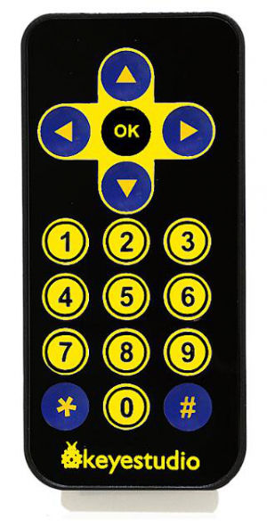
Below we have listed out each button value of keyestudio remote control. You can keep it for reference. | |||
<br>[[File:KS0313 4-1-7.png|800px|frameless|thumb]]<br> | |||
<br> | |||
Next, let’s use the remote control to make a small experiment. Use the remote control to make 8*8 dot matrix display different images. <br> | |||
<br> | |||
'''Hookup Guide:''' <br> | |||
Connect the IR receiver and dot matrix to the shield as the figure shown below: | |||
<br>[[File:Ks0364 - connection 11.png|800px|frameless|thumb]]<br> | |||
<br> | |||
Below is an example code. | |||
<br> | |||
'''Code 13:''' <br> | |||
'''Note:''' Before test the code, should add the dot matrix and IR receiver libraries to the Arduino libraries directory. If you have added them before, directly compile and upload the code below to Arduino software. <br> | |||
Download all the libraries folder from the link here: | |||
https://drive.google.com/open?id=16ii-ZQTNK_Fn8KG81rhBw7JX1zQQ6nG6 | |||
<pre> | |||
#// dot matrix | |||
#include <Wire.h> // add the IIC libraries | |||
#include "Adafruit_LEDBackpack.h" // add the libraries of dot matrix | |||
#include "Adafruit_GFX.h" | |||
Adafruit_LEDBackpack matrix = Adafruit_LEDBackpack(); // build an object to control the dot matrix | |||
// IR receiver | |||
#include <IRremote.h> // add the libraries of IR receiver | |||
int RECV_PIN = A0; // define the IR receiver pin as A0 | |||
IRrecv irrecv(RECV_PIN); | |||
decode_results results; | |||
// decoding of remote control | |||
const long IR_front = 0x00FF629D; | |||
const long IR_back = 0x00FFA857; | |||
const long IR_left = 0x00FF22DD; | |||
const long IR_right = 0x00FFC23D; | |||
const long IR_stop = 0x00FF02FD; | |||
const long IR_1 = 0x00FF6897; | |||
const long IR_2 = 0x00FF9867; | |||
const long IR_3 = 0x00FFB04F; | |||
const long IR_4 = 0x00FF30CF; | |||
const long IR_5 = 0x00FF18E7; | |||
const long IR_6 = 0x00FF7A85; | |||
const long IR_7 = 0x00FF10EF; | |||
const long IR_8 = 0x00FF38C7; | |||
const long IR_9 = 0x00FF5AA5; | |||
const long IR_0 = 0x00FF52AD; | |||
void setup() | |||
{ | |||
Serial.begin(9600); // set the baud rate to 9600 | |||
irrecv.enableIRIn(); // Start the receiver | |||
delay(100); //delay 100ms | |||
//dot matrix | |||
matrix.begin(0x70); // pass in the address | |||
chushi(); // the matrix display when starting up | |||
} | |||
void loop() | |||
{ | |||
if(irrecv.decode(&results)) // if receive the IR signal | |||
{ | |||
int val = results.value; // assign the received result to val | |||
Serial.println(val,HEX); // print out the hexadecimal val value on the serial monitor | |||
switch(val) // perform the corresponding function for the corresponding data received. | |||
{ | |||
case IR_front: qian(); break; // display the front arrow | |||
case IR_back: hou(); break; // display the back arrow | |||
case IR_left: zuo(); break; // display the left arrow | |||
case IR_right: you(); break; //display the right arrow | |||
case IR_stop: ting(); break; //display × | |||
case IR_1: S(); break; //display S | |||
case IR_2: ZZ(); break; // display the arrow flexed to the left | |||
case IR_3: YZ(); break; // display the arrow flexed to the right | |||
case IR_4: ZX(); break; // display the arrow turn right in circle | |||
case IR_5: YX(); break; // the arrow circle turn left in circle | |||
default : printf("error"); | |||
} | |||
irrecv.resume(); // Receive the next value | |||
} | |||
} | |||
////////////////////////matrix display image//////////////////////////// | |||
// forward | |||
void qian() | |||
{ | |||
matrix.displaybuffer[3] = B11111111; | |||
matrix.displaybuffer[4] = B11111111; | |||
matrix.displaybuffer[2] = B00000001; | |||
matrix.displaybuffer[1] = B00000010; | |||
matrix.displaybuffer[0] = B00000100; | |||
matrix.displaybuffer[5] = B00000001; | |||
matrix.displaybuffer[6] = B00000010; | |||
matrix.displaybuffer[7] = B00000100; | |||
matrix.writeDisplay(); | |||
} | |||
//backward | |||
void hou() | |||
{ | |||
matrix.displaybuffer[3] = B11111111; | |||
matrix.displaybuffer[4] = B11111111; | |||
matrix.displaybuffer[2] = B00100000; | |||
matrix.displaybuffer[1] = B00010000; | |||
matrix.displaybuffer[0] = B00001000; | |||
matrix.displaybuffer[5] = B00100000; | |||
matrix.displaybuffer[6] = B00010000; | |||
matrix.displaybuffer[7] = B00001000; | |||
matrix.writeDisplay(); | |||
} | |||
//turn right | |||
void you() | |||
{ | |||
for(int i=0;i<8;i++) | |||
{ | |||
matrix.displaybuffer[i] = B00001100; | |||
} | |||
matrix.displaybuffer[6] = B00011110; | |||
matrix.displaybuffer[5] = B00101101; | |||
matrix.displaybuffer[4] = B11001100; | |||
matrix.writeDisplay(); | |||
} | |||
//turn left | |||
void zuo() | |||
{ | |||
for(int i=0;i<8;i++) | |||
{ | |||
matrix.displaybuffer[i] = B00001100; | |||
} | |||
matrix.displaybuffer[1] = B00011110; | |||
matrix.displaybuffer[2] = B00101101; | |||
matrix.displaybuffer[3] = B11001100; | |||
matrix.writeDisplay(); | |||
} | |||
//stop | |||
void ting() | |||
{ | |||
matrix.displaybuffer[0] = B11000000; | |||
matrix.displaybuffer[1] = B00100001; | |||
matrix.displaybuffer[2] = B00010010; | |||
matrix.displaybuffer[3] = B00001100; | |||
matrix.displaybuffer[4] = B00001100; | |||
matrix.displaybuffer[5] = B00010010; | |||
matrix.displaybuffer[6] = B00100001; | |||
matrix.displaybuffer[7] = B11000000; | |||
matrix.writeDisplay(); | |||
} | |||
//start up | |||
void chushi() | |||
{ | |||
matrix.displaybuffer[0] = B00000011; | |||
matrix.displaybuffer[1] = B10000000; | |||
matrix.displaybuffer[2] = B00010011; | |||
matrix.displaybuffer[3] = B00100000; | |||
matrix.displaybuffer[4] = B00100000; | |||
matrix.displaybuffer[5] = B00010011; | |||
matrix.displaybuffer[6] = B10000000; | |||
matrix.displaybuffer[7] = B00000011; | |||
matrix.writeDisplay(); | |||
} | |||
//S line | |||
void S() | |||
{ | |||
matrix.displaybuffer[0] = B00000000; | |||
matrix.displaybuffer[1] = B00000000; | |||
matrix.displaybuffer[2] = B00110001; | |||
matrix.displaybuffer[3] = B11001000; | |||
matrix.displaybuffer[4] = B11000100; | |||
matrix.displaybuffer[5] = B00100011; | |||
matrix.displaybuffer[6] = B00000000; | |||
matrix.displaybuffer[7] = B00000000; | |||
matrix.writeDisplay(); | |||
} | |||
// turn around the wheel on the left | |||
void ZZ() | |||
{ | |||
matrix.displaybuffer[0] = B00000000; | |||
matrix.displaybuffer[1] = B10000011; | |||
matrix.displaybuffer[2] = B11000001; | |||
matrix.displaybuffer[3] = B10100010; | |||
matrix.displaybuffer[4] = B00010100; | |||
matrix.displaybuffer[5] = B00001000; | |||
matrix.displaybuffer[6] = B00000000; | |||
matrix.displaybuffer[7] = B00000000; | |||
matrix.writeDisplay(); | |||
} | |||
// turn around the wheel on the right | |||
void YZ() | |||
{ | |||
matrix.displaybuffer[0] = B00000000; | |||
matrix.displaybuffer[1] = B00000000; | |||
matrix.displaybuffer[2] = B00001000; | |||
matrix.displaybuffer[3] = B00010100; | |||
matrix.displaybuffer[4] = B10100010; | |||
matrix.displaybuffer[5] = B11000001; | |||
matrix.displaybuffer[6] = B10000011; | |||
matrix.displaybuffer[7] = B00000000; | |||
matrix.writeDisplay(); | |||
} | |||
// turn left in circle | |||
void ZX() | |||
{ | |||
matrix.displaybuffer[0] = B00000000; | |||
matrix.displaybuffer[1] = B00011100; | |||
matrix.displaybuffer[2] = B00100010; | |||
matrix.displaybuffer[3] = B01000001; | |||
matrix.displaybuffer[4] = B00000001; | |||
matrix.displaybuffer[5] = B00111001; | |||
matrix.displaybuffer[6] = B00110010; | |||
matrix.displaybuffer[7] = B00101100; | |||
matrix.writeDisplay(); | |||
} | |||
// turn right in circle | |||
void YX() | |||
{ | |||
matrix.displaybuffer[0] = B00001100; | |||
matrix.displaybuffer[1] = B00110010; | |||
matrix.displaybuffer[2] = B00111001; | |||
matrix.displaybuffer[3] = B00000001; | |||
matrix.displaybuffer[4] = B00000001; | |||
matrix.displaybuffer[5] = B00100010; | |||
matrix.displaybuffer[6] = B00011100; | |||
matrix.displaybuffer[7] = B00000000; | |||
matrix.writeDisplay(); | |||
} | |||
</pre> | |||
<br> | |||
'''What you will see?''' <br> | |||
Upload the above code to the board, and turn on the POWER button on the shield. Aligned with the IR receiver, use remote control to control the turtle robot run, showing the running states on the dot matrix display. | |||
<br>[[File:KS0364 图片11.png|500px|frameless|thumb]]<br> | |||
<br> | |||
==== 2) Infrared Control Turtle Robot ==== | |||
'''Overview:''' <br> | |||
In the previous section, we have introduced how to use an IR remote control to control a 8*8 dot matrix. So think that how to control the smart robot with an IR remote control. <br> | |||
It is very simple. Use ARDUINO board to analyze and judge the collected infrared signal so as to drive the motor forward,backward and turn. | |||
You can apply the decoding value of remote control mentioned before to the code that used to control the robot with IR remote control. | |||
It also adds a 8*8 dot matrix to display the running state of turtle robot. <br> | |||
<br> | |||
'''Wiring Diagram:''' <br> | |||
<br>[[File:Ks0364 - connection 12.png|700px|frameless|thumb]]<br> | |||
<br> | |||
Next let’s look back to the decoding value of IR remote control. | |||
<br>[[File:KS0313 4-1-7.png|800px|frameless|thumb]]<br> | |||
<br> | |||
You can get the details: <br> | |||
* Forward button: 0x00FF629D | |||
* Backward button: 0x00FFA857 | |||
* Stop button: 0x00FF02FD | |||
* Left button: 0x00FF22DD | |||
* Right Button: 0x00FFC23D | |||
You can apply those data to the code of infrared controlled robot. | |||
<br> | |||
'''Code 14:''' <br> | |||
'''Note:''' Before test the code, should add all the libraries needed to the Arduino libraries directory. If you have added them before, directly compile and upload the code below to Arduino software. <br> | |||
Download all the libraries folder from the link here: <br> | |||
https://drive.google.com/open?id=16ii-ZQTNK_Fn8KG81rhBw7JX1zQQ6nG6 | |||
<pre> | |||
//DOT MATRIX | |||
#include <Wire.h> // add IIC libraries | |||
#include "Adafruit_LEDBackpack.h" // add the libraries of matrix display | |||
#include "Adafruit_GFX.h" | |||
Adafruit_LEDBackpack matrix = Adafruit_LEDBackpack(); // build an object to control a dot matrix | |||
// IR receiver | |||
#include <IRremote.h> // add the libraries of IR receiver | |||
int RECV_PIN = A0; // define the ir receiver pin as A0 | |||
IRrecv irrecv(RECV_PIN); | |||
decode_results results; | |||
// decoding value of ir receiver | |||
const long IR_front = 0x00FF629D; | |||
const long IR_back = 0x00FFA857; | |||
const long IR_left = 0x00FF22DD; | |||
const long IR_right = 0x00FFC23D; | |||
const long IR_stop = 0x00FF02FD; | |||
const long IR_1 = 0x00FF6897; | |||
const long IR_2 = 0x00FF9867; | |||
const long IR_3 = 0x00FFB04F; | |||
const long IR_4 = 0x00FF30CF; | |||
const long IR_5 = 0x00FF18E7; | |||
const long IR_6 = 0x00FF7A85; | |||
const long IR_7 = 0x00FF10EF; | |||
const long IR_8 = 0x00FF38C7; | |||
const long IR_9 = 0x00FF5AA5; | |||
const long IR_0 = 0x00FF52AD; | |||
// control two motors | |||
#define INT_A 2 // control the left motor direction pin D2 | |||
#define INT_B 4 // control the right motor direction pin D4 | |||
#define left_A 9 // define the left motor speed control pin as D9 | |||
#define right_B 5 // define the right motor speed control pin as D5 | |||
int i=0; | |||
long val; // define a variable to receive the signal sent by IR transmitter | |||
void setup() | |||
{ | |||
Serial.begin(9600); // set the serial baud rate to 9600 | |||
irrecv.enableIRIn(); // Start the receiver | |||
delay(100); // delay 100ms | |||
pinMode(INT_A,OUTPUT); // set the motor control pin as OUTPUT | |||
pinMode(INT_B,OUTPUT); | |||
pinMode(left_A,OUTPUT); | |||
pinMode(right_B,OUTPUT); | |||
// DOT MATRIX | |||
matrix.begin(0x70); // pass in the address | |||
chushi(); //initial matrix display | |||
} | |||
void loop() | |||
{ | |||
i = 1; | |||
if(irrecv.decode(&results)) // if receive the infrared signal | |||
{ | |||
val = results.value; // assign the result value to val | |||
Serial.println(val,HEX); // print out hexadecimal val value on the serial monitor | |||
switch(val) // perform the corresponding function for the received data | |||
{ | |||
case IR_front: front(),qian(); break; // if receive the(IR_front = 0x00FF629D),perform the front function(front())and matrix display function(qian()) | |||
case IR_back: back(),hou(); break; // backward | |||
case IR_left: left(),zuo(); break; // turn left | |||
case IR_right: right(),you(); break; // turn right | |||
case IR_stop: Stop(),ting(); break; // stop | |||
case IR_1: front_s(); break; // walk in S line | |||
case IR_2: left_l(),ZZ(); break; // turn around the wheel on the left | |||
case IR_3: right_l(),YZ(); break; // turn around the wheel on the right | |||
case IR_4: right_r(),ZX(); break; // turn a circle to the right | |||
case IR_5: left_r(),YX(); break; // turn a circle to the left | |||
default : printf("error"); | |||
} | |||
irrecv.resume(); // Receive the next value | |||
} | |||
} | |||
// go forward | |||
void front() | |||
{ | |||
digitalWrite(INT_A,LOW); // control the left motor turn forward | |||
digitalWrite(INT_B,LOW); // control the right motor turn forward | |||
analogWrite(left_A,200); // set the two motors’ speed(PWM=200) | |||
analogWrite(right_B,200); | |||
} | |||
// backward | |||
void back() | |||
{ | |||
digitalWrite(INT_A,HIGH); // control the left motor turn backward | |||
digitalWrite(INT_B,HIGH); // control the right motor turn backward | |||
analogWrite(left_A,200); // set the two motors’ speed (PWM=200) | |||
analogWrite(right_B,200); | |||
} | |||
// turn left | |||
void left() | |||
{ | |||
digitalWrite(INT_A,HIGH); // control the left motor turn backward | |||
digitalWrite(INT_B,LOW); // control the right motor turn forward | |||
analogWrite(left_A,100); // set the two motors’ speed(PWM为100) | |||
analogWrite(right_B,100); | |||
} | |||
// turn right | |||
void right() | |||
{ | |||
digitalWrite(INT_A,LOW); // control the left motor turn forward | |||
digitalWrite(INT_B,HIGH); // control the right motor turn backward | |||
analogWrite(left_A,100); // two motors’ speed(PWM为100) | |||
analogWrite(right_B,100); | |||
} | |||
// stop | |||
void Stop() | |||
{ | |||
digitalWrite(INT_A,LOW); | |||
digitalWrite(INT_B,LOW); | |||
analogWrite(left_A,0); // both PWM are 0 | |||
analogWrite(right_B,0); | |||
} | |||
//walk in S line | |||
void front_s() | |||
{ | |||
S(); | |||
while(i>0) | |||
{ | |||
digitalWrite(INT_A,LOW); // control the left motor turn forward | |||
digitalWrite(INT_B,LOW); // control the right motor turn forward | |||
analogWrite(left_A,50); // left motor PWM=100 | |||
analogWrite(right_B,255); // right motor PWM=255 (walk in S line to the left) | |||
delay(300); // delay 1S | |||
analogWrite(left_A,255); // left motor PWM=255 | |||
analogWrite(right_B,50); // right motor PWM=100 (walk in S line to the right) | |||
delay(300); // delay 1S | |||
if(irrecv.decode(&results)) // if receive the infrared signal | |||
{ | |||
irrecv.resume(); // Receive the next value | |||
val=results.value; // assign the received data to val | |||
if(val==IR_stop) // if receive the stop command | |||
{ | |||
Stop(); // stop | |||
break; // exit the current function | |||
} | |||
} | |||
} | |||
} | |||
//turn around the wheel on the left | |||
void left_l() | |||
{ | |||
digitalWrite(INT_A,HIGH); // control the left motor turn backward | |||
digitalWrite(INT_B,LOW); // control the right motor turn forward | |||
analogWrite(left_A,0); //left PWM=0,left wheel stops | |||
analogWrite(right_B,200); //right PWM=200,right wheel goes front | |||
} | |||
// turn around the wheel on the right | |||
void right_l() | |||
{ | |||
digitalWrite(INT_A,HIGH); // control the left motor turn backward | |||
digitalWrite(INT_B,LOW); // control the right motor turn forward | |||
analogWrite(left_A,200); //left PWM=200, left wheel goes forward | |||
analogWrite(right_B,0); //right PWM=0,right wheel stops | |||
} | |||
// turn a circle to the right | |||
void right_r() | |||
{ | |||
digitalWrite(INT_A,LOW); // control the left motor turn forward | |||
digitalWrite(INT_B,LOW); // control the right motor turn forward | |||
analogWrite(left_A,100); // left motor PWM=100 | |||
analogWrite(right_B,200); // right motor PWM=200 (car turns around to the left) | |||
} | |||
// turn around to the left | |||
void left_r() | |||
{ | |||
digitalWrite(INT_A,LOW); // control the left motor turn forward | |||
digitalWrite(INT_B,LOW); // control the right motor turn forward | |||
analogWrite(left_A,200); // left motor PWM=100 | |||
analogWrite(right_B,100); // right motor PWM=200 ( car turns around to the left) | |||
} | |||
////////////////////////matrix display image//////////////////////////// | |||
// front image | |||
void qian() | |||
{ | |||
matrix.displaybuffer[3] = B11111111; | |||
matrix.displaybuffer[4] = B11111111; | |||
matrix.displaybuffer[2] = B00000001; | |||
matrix.displaybuffer[1] = B00000010; | |||
matrix.displaybuffer[0] = B00000100; | |||
matrix.displaybuffer[5] = B00000001; | |||
matrix.displaybuffer[6] = B00000010; | |||
matrix.displaybuffer[7] = B00000100; | |||
matrix.writeDisplay(); | |||
} | |||
// back image | |||
void hou() | |||
{ | |||
matrix.displaybuffer[3] = B11111111; | |||
matrix.displaybuffer[4] = B11111111; | |||
matrix.displaybuffer[2] = B00100000; | |||
matrix.displaybuffer[1] = B00010000; | |||
matrix.displaybuffer[0] = B00001000; | |||
matrix.displaybuffer[5] = B00100000; | |||
matrix.displaybuffer[6] = B00010000; | |||
matrix.displaybuffer[7] = B00001000; | |||
matrix.writeDisplay(); | |||
} | |||
//right image | |||
void you() | |||
{ | |||
for(int i=0;i<8;i++) | |||
{ | |||
matrix.displaybuffer[i] = B00001100; | |||
} | |||
matrix.displaybuffer[6] = B00011110; | |||
matrix.displaybuffer[5] = B00101101; | |||
matrix.displaybuffer[4] = B11001100; | |||
matrix.writeDisplay(); | |||
} | |||
// left image | |||
void zuo() | |||
{ | |||
for(int i=0;i<8;i++) | |||
{ | |||
matrix.displaybuffer[i] = B00001100; | |||
} | |||
matrix.displaybuffer[1] = B00011110; | |||
matrix.displaybuffer[2] = B00101101; | |||
matrix.displaybuffer[3] = B11001100; | |||
matrix.writeDisplay(); | |||
} | |||
// stop image | |||
void ting() | |||
{ | |||
matrix.displaybuffer[0] = B11000000; | |||
matrix.displaybuffer[1] = B00100001; | |||
matrix.displaybuffer[2] = B00010010; | |||
matrix.displaybuffer[3] = B00001100; | |||
matrix.displaybuffer[4] = B00001100; | |||
matrix.displaybuffer[5] = B00010010; | |||
matrix.displaybuffer[6] = B00100001; | |||
matrix.displaybuffer[7] = B11000000; | |||
matrix.writeDisplay(); | |||
} | |||
// initial image | |||
void chushi() | |||
{ | |||
matrix.displaybuffer[0] = B00000011; | |||
matrix.displaybuffer[1] = B10000000; | |||
matrix.displaybuffer[2] = B00010011; | |||
matrix.displaybuffer[3] = B00100000; | |||
matrix.displaybuffer[4] = B00100000; | |||
matrix.displaybuffer[5] = B00010011; | |||
matrix.displaybuffer[6] = B10000000; | |||
matrix.displaybuffer[7] = B00000011; | |||
matrix.writeDisplay(); | |||
} | |||
//S line | |||
void S() | |||
{ | |||
matrix.displaybuffer[0] = B00000000; | |||
matrix.displaybuffer[1] = B00000000; | |||
matrix.displaybuffer[2] = B00110001; | |||
matrix.displaybuffer[3] = B11001000; | |||
matrix.displaybuffer[4] = B11000100; | |||
matrix.displaybuffer[5] = B00100011; | |||
matrix.displaybuffer[6] = B00000000; | |||
matrix.displaybuffer[7] = B00000000; | |||
matrix.writeDisplay(); | |||
} | |||
// turn around the wheel on the left | |||
void ZZ() | |||
{ | |||
matrix.displaybuffer[0] = B00000000; | |||
matrix.displaybuffer[1] = B10000011; | |||
matrix.displaybuffer[2] = B11000001; | |||
matrix.displaybuffer[3] = B10100010; | |||
matrix.displaybuffer[4] = B00010100; | |||
matrix.displaybuffer[5] = B00001000; | |||
matrix.displaybuffer[6] = B00000000; | |||
matrix.displaybuffer[7] = B00000000; | |||
matrix.writeDisplay(); | |||
} | |||
// turn around the wheel on the right | |||
void YZ() | |||
{ | |||
matrix.displaybuffer[0] = B00000000; | |||
matrix.displaybuffer[1] = B00000000; | |||
matrix.displaybuffer[2] = B00001000; | |||
matrix.displaybuffer[3] = B00010100; | |||
matrix.displaybuffer[4] = B10100010; | |||
matrix.displaybuffer[5] = B11000001; | |||
matrix.displaybuffer[6] = B10000011; | |||
matrix.displaybuffer[7] = B00000000; | |||
matrix.writeDisplay(); | |||
} | |||
// turn around to the left | |||
void ZX() | |||
{ | |||
matrix.displaybuffer[0] = B00000000; | |||
matrix.displaybuffer[1] = B00011100; | |||
matrix.displaybuffer[2] = B00100010; | |||
matrix.displaybuffer[3] = B01000001; | |||
matrix.displaybuffer[4] = B00000001; | |||
matrix.displaybuffer[5] = B00111001; | |||
matrix.displaybuffer[6] = B00110010; | |||
matrix.displaybuffer[7] = B00101100; | |||
matrix.writeDisplay(); | |||
} | |||
// turn around to the right | |||
void YX() | |||
{ | |||
matrix.displaybuffer[0] = B00001100; | |||
matrix.displaybuffer[1] = B00110010; | |||
matrix.displaybuffer[2] = B00111001; | |||
matrix.displaybuffer[3] = B00000001; | |||
matrix.displaybuffer[4] = B00000001; | |||
matrix.displaybuffer[5] = B00100010; | |||
matrix.displaybuffer[6] = B00011100; | |||
matrix.displaybuffer[7] = B00000000; | |||
matrix.writeDisplay(); | |||
} | |||
</pre> | |||
<br> | |||
'''What you will see?''' <br> | |||
Upload the above code to the board, and turn on the POWER button on the shield. Aligned with the IR receiver, use remote control to control the turtle robot run, showing the running states on the dot matrix display. | |||
<br>[[File:Ks0364 IR.jpg|500px|frameless|thumb]]<br> | |||
<br> | |||
<br> | |||
===Project 5: Bluetooth Controlled Robot === | |||
<br> | |||
====1) Principle and Application of Bluetooth Remote Control==== | |||
<br> | |||
Bluetooth, as the name implies, blue teeth, and he is not used to bite people, but a wireless data transmission method. Bluetooth technology is a wireless standard technology that enables short-range data exchange among fixed devices, mobile devices, and personal area networks of buildings (UHF radio waves in the ISM band of 2.4 to 2.485 GHz). <br> | |||
There are two kinds of commonly used Bluetooth module on the market, HC-05 and HC-06 models. The difference between them is that the HC-05 is a master-slave one. <br> | |||
It can not only make small reports to its own “master”, but also can receive the command given to it. The HC-06 can only work in slave mode, which can only accept the superior command. For instance, in many cases you may want to be an overbearing man, letting the subordinates obey the order without any nonsense. So in such situation, it is enough to use the HC-06 module shown as below. | |||
<br>[[File:KS0313 5-1-1.png|800px|frameless|thumb]]<br> | |||
<br> | |||
'''Specification Parameters:'''<br> | |||
* 1) Bluetooth Protocol: Bluetooth 2.1+ EDR Standard <br> | |||
* 2) USB Protocol: USB v1.1/2.0 <br> | |||
* 3) Operating Frequency: 2.4GHz ISM Frequency Band <br> | |||
* 4) Modulation Mode: Gauss Frequency Shift Keying <br> | |||
* 5) Transmit Power: ≤ 4dBm, Second Stage <br> | |||
* 6) Sensitivity: ≤-84dBm at 0.1% Bit Error Rate <br> | |||
* 7) Transmission Speed: 2.1Mbps(Max)/160 kbps(Asynchronous);1Mbps/1Mbps(Synchronous) <br> | |||
* 8) Safety Feature: Authentication and Encryption <br> | |||
* 9) Supported Configuration: Bluetooth Serial Port (major and minor) <br> | |||
* 10) Supply Voltage: DC 5V <br> | |||
* 11) Operating Temperature: -20 to 55℃ <br> | |||
<br> | |||
'''Wiring Diagram:'''<br> | |||
Next, we are going to do a small experiment. When Bluetooth module receives a signal sent by phone, finally control an LED on and off. | |||
<br>[[File:Ks0364 - connection 13.png|800px|frameless|thumb]]<br> | |||
<br> | |||
'''Test Code 15:'''<br> | |||
<pre> | |||
int val; | |||
int led=11; | |||
void setup() | |||
{ | |||
Serial.begin(9600); | |||
pinMode(11,OUTPUT); | |||
} | |||
void loop() | |||
{ val=Serial.read(); | |||
if(val=='U') | |||
{ | |||
digitalWrite(11, HIGH); // turn the LED on (HIGH is the voltage level) | |||
} | |||
if(val=='D') | |||
{ | |||
digitalWrite(11, LOW); // turn the LED off by making the voltage LOW | |||
} | |||
} | |||
</pre> | |||
<br> | |||
After wiring, upload the above code to the board, and connect the Bluetooth module. Pay more attention to the connecting direction. Plug it correctly and you should see an LED on the module flash. | |||
<br>[[File:KS0313 5-1-3.png|600px|frameless|thumb]]<br> | |||
<br> | |||
<span style="color: red">''' Pay special attention to:''' <br> | |||
You must first upload the code to the board and then plug in the Bluetooth module, otherwise the program fails to compile. Because the data transmits of Bluetooth module will occupy the microcontroller’s TX and RX pins that are also used for the code upload of microcontroller, it exists a conflict. </span > <br> | |||
After uploading the code, you have to do another thing, that is, install an application of Bluetooth serial assistant on the phone. <br> | |||
[[File:KS0313 5-1-4.png|400px|thumb|right]] | |||
You can click the link below to download the Bluetooth serial assistant: <br> | |||
https://drive.google.com/open?id=1D16V4HZ5H6k7p1-NMCqb0JRy_dl5tvuC | |||
<br> | |||
The Bluetooth we used here is Bluetooth 2.0. Currently, it only supports the Android devices. Do not support Apple devices. Please pay attention to this when using it. | |||
<br> | |||
After the serial assistant is installed, must first connect the device, open the mobile Bluetooth, search for a Bluetooth device. If find a Bluetooth device named HC-06, pair and enter 1234, finally you should see the paired device shown as below. | |||
<br>[[File:KS0313 5-1-5.png|600px|frameless|thumb]] [[File:Ks0364 bluetooth (2).jpg|250px|frameless|thumb]] [[File:Ks0364 U.jpg|250px|frameless|thumb]] <br> | |||
<br> | |||
Then open the Bluetooth serial communication APP, namely BT Client, and connect well the Bluetooth just paired. <br> | |||
Done connecting, an LED on the Bluetooth module is always on. If enter the letter '''U''' in the Bluetooth APP, the LED connected on the pin 11is on; if enter the letter '''D''', the LED is off. | |||
<br>[[File:Ks0364-U.JPG|500px|frameless|thumb]]<br> | |||
<br> | |||
====2) Bluetooth Controlled Turtle Robot ==== | |||
In the previous section, you have learned the principles of Bluetooth and how to use Bluetooth to control a small light. Okay, based on that, could we use Bluetooth to send a command to control the robot run? <br> | |||
Absolutely yeah. In the previous section, we can use a mobile APP to send a character. Use a Bluetooth module to receive the Bluetooth signal from the mobile phone, and feed it back to the main control board. Then main control board will analyze and judge the collected signals. If correct, it will control the robot run. <br> | |||
Here we don't need a Bluetooth serial assistant as mentioned above. Just use an Android APP developed by our keyestudio team to control the robot. <br> | |||
[[File:KS0313 5-2-1.png|800px|thumb|right]] | |||
You can click the link to download the APP: <br> | |||
https://drive.google.com/open?id=1g-bwP1SyJVfQseywRORQ6rOJOVd3JU5i | |||
<br> | |||
The interface of this APP is very simple, as shown below. | |||
<br>[[File:KS0313 5-2-2.png|800px|frameless|thumb]] <br> | |||
<br> | |||
Connected the Bluetooth, let’s make use of a little program that can read the serial data, to check what character the five buttons send. Then apply them to the example code for Bluetooth robot in the following projects.<br> | |||
<br> | |||
'''Test Code 16:''' | |||
<pre> | |||
char val; // define the variable val | |||
void setup() | |||
{ | |||
Serial.begin(9600);// set the baud rate as 9600, the same as software setting. When connecting the particular device like Bluetooth, it should be consistent with the baud rate of other devices. | |||
} | |||
void loop() | |||
{ | |||
val=Serial.read();//read the data received from serial port, and assign it to val | |||
Serial.println(val);// print val data | |||
delay(300);//delay 0.3S | |||
} | |||
</pre> | |||
<br> | |||
Through the above program, we can get that five buttons are Upward (“U”), Downward (“D”), Left (“L”), Right (“R”), and Stop (“S”). The principle is very simple. <br> | |||
When Bluetooth module receives these characters sent by the mobile phone, and then it will send them to ARDUINO. ARDUINO will control the rotation direction of motor according to the preset value in the code. <br> | |||
When receive the information "U", smart robot will move forward. When receive "D", it goes backward. If receive "L", turn left. If receive "R", turn right. The smart car will stop when receive the "S". <br> | |||
<br> | |||
'''Hookup Guide:''' <br> | |||
'''Note:''' Bluetooth module is directly plugged into the shield. <br> | |||
<br>[[File:Ks0364 - connection 14.png|800px|frameless|thumb]] <br> | |||
<br> | |||
After wiring, you can get the project code as follows: <br> | |||
<br> | |||
'''Test Code 17:''' <br> | |||
'''Note:''' Before test the code, should add the libraries needed to the Arduino libraries directory. If you have added them before, directly compile and upload the code below to Arduino software. <br> | |||
Download all the libraries folder from the link here: <br> | |||
https://drive.google.com/open?id=16ii-ZQTNK_Fn8KG81rhBw7JX1zQQ6nG6 | |||
<br> | |||
<span style="color: red"> '''Pay special attention:''' </span > should first upload the code successfully, then connect the Bluetooth module. Otherwise, fail to upload the code.<br> | |||
<pre> | |||
#include <Wire.h> | |||
#include "Adafruit_LEDBackpack.h" | |||
#include "Adafruit_GFX.h" | |||
Adafruit_LEDBackpack matrix = Adafruit_LEDBackpack(); | |||
#define INT_A 2 //define the left motor control pin as D2 | |||
#define INT_B 4 // define the right motor control pin as D4 | |||
#define left_A 9 // define the left motor speed pin as D9 | |||
#define right_B 5 // define the right motor speed pin as D5 | |||
void setup() | |||
{ | |||
Serial.begin(9600); // set the baud rate of monitor to 9600 | |||
delay(100); //delay 100ms | |||
pinMode(INT_A,OUTPUT); // set the motor control pin as OUTPUT | |||
pinMode(INT_B,OUTPUT); | |||
pinMode(left_A,OUTPUT); | |||
pinMode(right_B,OUTPUT); | |||
// DOT matrix | |||
matrix.begin(0x70); // pass in the address | |||
chushi(); // initial matrix image | |||
} | |||
void loop() | |||
{ | |||
int val; //define the variable, used to receive the data from Bluetooth | |||
if(Serial.available()) // if receive the data | |||
{ | |||
val = Serial.read(); // assign the data read to val | |||
} | |||
switch(val) // perform the corresponding function for data received | |||
{ | |||
case 'U': front(),qian(); break; //if val equals U,then perform the front function(front())and image function(qian()),break statement means that exist the current function if receive other data | |||
case 'D': back(),hou(); break; //backward | |||
case 'L': left(),zuo(); break; // turn left | |||
case 'R': right(),you(); break; // turn right | |||
case 'S': Stop(),ting(); break; // stop | |||
default :Serial.print("error"); | |||
} | |||
} | |||
// go front | |||
void front() | |||
{ | |||
digitalWrite(INT_A,LOW); // control the left motor rotate forward | |||
digitalWrite(INT_B,LOW); // control the right motor rotate forward | |||
analogWrite(left_A,200); // set the two motors’ speed(PWM=200) | |||
analogWrite(right_B,200); | |||
} | |||
// backward | |||
void back() | |||
{ | |||
digitalWrite(INT_A,HIGH); // control the left motor rotate backward | |||
digitalWrite(INT_B,HIGH); // control the right motor rotate backward | |||
analogWrite(left_A,200); | |||
analogWrite(right_B,200); | |||
} | |||
// turn left | |||
void left() | |||
{ | |||
digitalWrite(INT_A,HIGH); // control the left motor rotate backward | |||
digitalWrite(INT_B,LOW); // control the right motor rotate forward | |||
analogWrite(left_A,100); // two motors’ speed(PWM为100) | |||
analogWrite(right_B,100); | |||
} | |||
// turn right | |||
void right() | |||
{ | |||
digitalWrite(INT_A,LOW); // control the left motor rotate forward | |||
digitalWrite(INT_B,HIGH); // control the right motor rotate backward | |||
analogWrite(left_A,100); | |||
analogWrite(right_B,100); | |||
} | |||
// stop | |||
void Stop() | |||
{ | |||
digitalWrite(INT_A,LOW); | |||
digitalWrite(INT_B,LOW); | |||
analogWrite(left_A,0); //both PWM are 0 | |||
analogWrite(right_B,0); | |||
} | |||
/////////////////////dot matrix///////////////////////// | |||
// front image | |||
void qian() | |||
{ | |||
matrix.displaybuffer[3] = B11111111; | |||
matrix.displaybuffer[4] = B11111111; | |||
matrix.displaybuffer[2] = B00000001; | |||
matrix.displaybuffer[1] = B00000010; | |||
matrix.displaybuffer[0] = B00000100; | |||
matrix.displaybuffer[5] = B00000001; | |||
matrix.displaybuffer[6] = B00000010; | |||
matrix.displaybuffer[7] = B00000100; | |||
matrix.writeDisplay(); | |||
} | |||
// backward image | |||
void hou() | |||
{ | |||
matrix.displaybuffer[3] = B11111111; | |||
matrix.displaybuffer[4] = B11111111; | |||
matrix.displaybuffer[2] = B00100000; | |||
matrix.displaybuffer[1] = B00010000; | |||
matrix.displaybuffer[0] = B00001000; | |||
matrix.displaybuffer[5] = B00100000; | |||
matrix.displaybuffer[6] = B00010000; | |||
matrix.displaybuffer[7] = B00001000; | |||
matrix.writeDisplay(); | |||
} | |||
// turn right image | |||
void you() | |||
{ | |||
for(int i=0;i<8;i++) | |||
{ | |||
matrix.displaybuffer[i] = B00001100; | |||
} | |||
matrix.displaybuffer[6] = B00011110; | |||
matrix.displaybuffer[5] = B00101101; | |||
matrix.displaybuffer[4] = B11001100; | |||
matrix.writeDisplay(); | |||
} | |||
// turn left image | |||
void zuo() | |||
{ | |||
for(int i=0;i<8;i++) | |||
{ | |||
matrix.displaybuffer[i] = B00001100; | |||
} | |||
matrix.displaybuffer[1] = B00011110; | |||
matrix.displaybuffer[2] = B00101101; | |||
matrix.displaybuffer[3] = B11001100; | |||
matrix.writeDisplay(); | |||
} | |||
// stop image | |||
void ting() | |||
{ | |||
matrix.displaybuffer[0] = B11000000; | |||
matrix.displaybuffer[1] = B00100001; | |||
matrix.displaybuffer[2] = B00010010; | |||
matrix.displaybuffer[3] = B00001100; | |||
matrix.displaybuffer[4] = B00001100; | |||
matrix.displaybuffer[5] = B00010010; | |||
matrix.displaybuffer[6] = B00100001; | |||
matrix.displaybuffer[7] = B11000000; | |||
matrix.writeDisplay(); | |||
} | |||
// initial image | |||
void chushi() | |||
{ | |||
matrix.displaybuffer[0] = B00000011; | |||
matrix.displaybuffer[1] = B10000000; | |||
matrix.displaybuffer[2] = B00010011; | |||
matrix.displaybuffer[3] = B00100000; | |||
matrix.displaybuffer[4] = B00100000; | |||
matrix.displaybuffer[5] = B00010011; | |||
matrix.displaybuffer[6] = B10000000; | |||
matrix.displaybuffer[7] = B00000011; | |||
matrix.writeDisplay(); | |||
} | |||
</pre> | |||
<br> | |||
'''Example Result:''' <br> | |||
Done uploading the above code to control board, turn on the POWER button on the shield, then open APP, connect to Bluetooth, you should see the LED on the Bluetooth module is normally on. <br> | |||
Press down any buttons on APP, you can control the smart robot to run freely, showing the state image on the dot matrix display. | |||
<br>[[File:Ks0364 Bluetooth.jpg|500px|frameless|thumb]] <br> | |||
<br> | |||
===Project 6: 4 in 1 Complete Robot === | |||
'''Overview:''' <br> | |||
In the above projects, we have introduced four functions for the turtle robot, that is, line following, avoiding obstacles, IR control and Bluetooth remote control. <br> | |||
Now, let’s combine those functions together to make a complete robot. You can use the IR module to switch the functions. <br> | |||
'''Function switching methods:''' <br> | |||
Powered on and aligned with the IR receiver, press the number 1 on the IR remote control, the turtle robot will enter the line tracking function. Then press the key OK, it will exist the tracking function. <br> | |||
* If press the number 2, enter the obstacle avoidance function, and press OK to end that function. <br> | |||
* If press the number 3, enter the S line forward, and press OK to end the function. | |||
* If press the number 4, the robot will turn around the wheel on the left, and press OK to end the function. | |||
* If press the number 5, the robot will turn a circle to the left, and press OK to end the function. | |||
* If press the number 6, the robot will turn a circle to the right, and press OK to end the function. <br> | |||
When exist the function modes, be able to control the car through infrared control or Phone-Bluetooth control. <br> | |||
<br> | |||
'''Hookup Guide:''' <br> | |||
<br>[[File:Ks0364 - connection 15.png|700px|frameless|thumb]] <br> | |||
<br> | |||
'''Test Code 18:''' <br> | |||
<span style="color: red">''' Note:''' </span > Before test the code, should add all the libraries needed to the Arduino libraries directory. If you have added them before, directly compile and upload the code below to Arduino software. <br> | |||
Download all the libraries folder from the link here: <br> | |||
https://drive.google.com/open?id=16ii-ZQTNK_Fn8KG81rhBw7JX1zQQ6nG6 | |||
<pre> | |||
// dot matrix | |||
#include <Wire.h> // add IIC file | |||
#include "Adafruit_LEDBackpack.h" | |||
#include "Adafruit_GFX.h" | |||
Adafruit_LEDBackpack matrix = Adafruit_LEDBackpack(); // build an object to control the dot matrix | |||
// IR receiver | |||
#include <IRremote.h> // add the IR receiver libraries | |||
int RECV_PIN = A0; // define the IR receiver pin as A0 | |||
IRrecv irrecv(RECV_PIN); | |||
decode_results results; | |||
// decoding of IR remote control | |||
const long IR_front = 0x00FF629D; | |||
const long IR_back = 0x00FFA857; | |||
const long IR_left = 0x00FF22DD; | |||
const long IR_right = 0x00FFC23D; | |||
const long IR_stop = 0x00FF02FD; | |||
const long IR_1 = 0x00FF6897; | |||
const long IR_2 = 0x00FF9867; | |||
const long IR_3 = 0x00FFB04F; | |||
const long IR_4 = 0x00FF30CF; | |||
const long IR_5 = 0x00FF18E7; | |||
const long IR_6 = 0x00FF7A85; | |||
const long IR_7 = 0x00FF10EF; | |||
const long IR_8 = 0x00FF38C7; | |||
const long IR_9 = 0x00FF5AA5; | |||
const long IR_0 = 0x00FF52AD; | |||
// line following | |||
const int S1 = 8; // the S1 tracking sensor control pin to D8 | |||
const int S2 = 7; // the S2 tracking sensor control pin to D7 | |||
const int S3 = 6; // the S3 tracking sensor control pin to D6 | |||
int s1,s2,s3; // define 3 variables,separately used to receive the digital value read by 3 tracking sensors(0 or 1) | |||
// avoiding obstacles | |||
const int servopin=3;// define the digital 3 to connect to servo signal line | |||
//int myangle;// define the angle | |||
//int pulsewidth;// define the pulsewidth | |||
#include <SR04.h> // add the ultrasonic libraries | |||
#define TRIG_PIN 12 // define the pin ting of ultrasonic as D12 | |||
#define ECHO_PIN 13 // define the pin echo of ultrasonic as D13 | |||
SR04 sr04 = SR04(ECHO_PIN,TRIG_PIN); // build an object to control the ultrasonic | |||
long a,a1,a2; // used to receive the distance measured by ultrasonic | |||
// end the obstacle avoidance | |||
// control two motors | |||
#define INT_A 2 // control the left motor direction pin as D2 | |||
#define INT_B 4 // control the right motor direction pin as D4 | |||
#define left_A 9 // control the left motor speed pin as D9 | |||
#define right_B 5 //control the right motor direction pin as D5 | |||
long val; // define a variable to receive the signal from IR transmitter | |||
int i=0; | |||
void setup() | |||
{ | |||
Serial.begin(9600); // set the baud rate of serial monitor to 9600 | |||
irrecv.enableIRIn(); // Start the receiver | |||
delay(100); // delay 100ms | |||
pinMode(INT_A,OUTPUT); // set the motor control pin as OUTPUT | |||
pinMode(INT_B,OUTPUT); | |||
pinMode(left_A,OUTPUT); | |||
pinMode(right_B,OUTPUT); | |||
// DOT matrix | |||
matrix.begin(0x70); // pass in the address | |||
chushi(); // initial matrix display | |||
pinMode(servopin,OUTPUT);// set the servo pin as OUTPUT | |||
// make the ultrasonic turn front | |||
for(int i=0;i<=100;i++) // give enough time to servo to rotate to specific angle | |||
{ | |||
digitalWrite(servopin,HIGH);// set the servo pin to HIGH | |||
delayMicroseconds(1200);// delay the microseconds of pulsewidth | |||
digitalWrite(servopin,LOW);// set the servo pin to LOW | |||
delayMicroseconds(18800);// delay the microseconds of pulsewidth | |||
} | |||
} | |||
void loop() | |||
{ | |||
i=1; | |||
Bluetooth(); // Bluetooth control | |||
if(irrecv.decode(&results)) // if receive the infrared signal | |||
{ | |||
val = results.value; // assign the result to val | |||
Serial.println(val,HEX); // print out the hexadecimal val value on the monitor | |||
irrecv.resume(); // Receive the next value | |||
} | |||
switch(val) // perform the corresponding function for the data received | |||
{ | |||
case IR_front: front(),qian(); break; // go front and display the front image //if val equals to IR_front(IR_front=0x00FF629D),perform front() and qian() these two subfunctions,break statement is used to exist the current function | |||
case IR_back: back(),hou(); break; // backward and show the back image | |||
case IR_left: left(),zuo(); break; // turn left and show the left image | |||
case IR_right: right(),you(); break; // turn right and show the right image | |||
case IR_stop: Stop(),ting(); break; // stop and show the stop image | |||
case IR_1: xunji(),val=0; break; // enter the tracking function( press stop to end the function) | |||
case IR_2: bizhang(),val=0; break; // enter the obstacle avoiding function( press stop to end the function) | |||
case IR_3: left_l(),ZZ(); break; // turn around the wheel on the left | |||
case IR_4: right_run(),YX(); break; // turn around to the right | |||
case IR_5: front_s(); break; // go front in S line and display S image | |||
case IR_6: left_run(),ZX(); break; // turn around to the left | |||
default : printf("error"); | |||
} | |||
} | |||
// go front | |||
void front() | |||
{ | |||
digitalWrite(INT_A,LOW); // control the left motor turn forward | |||
digitalWrite(INT_B,LOW); // control the right motor turn forward | |||
analogWrite(left_A,200); // set the two motors’ speed (PWM=200) | |||
analogWrite(right_B,200); | |||
} | |||
// go backward | |||
void back() | |||
{ | |||
digitalWrite(INT_A,HIGH); // control the left motor turn backward | |||
digitalWrite(INT_B,HIGH); // control the right motor turn backward | |||
analogWrite(left_A,200); // set the two motors’ speed(PWM=200) | |||
analogWrite(right_B,200); | |||
} | |||
// turn left | |||
void left() | |||
{ | |||
digitalWrite(INT_A,HIGH); // control the left motor turn backward | |||
digitalWrite(INT_B,LOW); // control the right motor turn forward | |||
analogWrite(left_A,150); // set the two motors’ speed(PWM为150) | |||
analogWrite(right_B,150); | |||
} | |||
//turn right | |||
void right() | |||
{ | |||
digitalWrite(INT_A,LOW); // control the left motor turn forward | |||
digitalWrite(INT_B,HIGH); // control the right motor turn backward | |||
analogWrite(left_A,150); // set the two motors’ speed(PWM为150) | |||
analogWrite(right_B,150); | |||
} | |||
// stop | |||
void Stop() | |||
{ | |||
digitalWrite(INT_A,LOW); | |||
digitalWrite(INT_B,LOW); | |||
analogWrite(left_A,0); // both PWM are 0 | |||
analogWrite(right_B,0); | |||
} | |||
// turn around the wheel on the left | |||
void left_l() | |||
{ | |||
digitalWrite(INT_A,HIGH); // control the left motor turn backward | |||
digitalWrite(INT_B,LOW); // control the right motor turn forward | |||
analogWrite(left_A,0); //left PWM=0,means that the left wheel stops | |||
analogWrite(right_B,255); //right PWM=255,right wheel goes forward | |||
} | |||
// turn around to the right | |||
void right_run() | |||
{ | |||
digitalWrite(INT_A,LOW); //control the left motor turn forward | |||
digitalWrite(INT_B,LOW); // control the right motor turn forward | |||
analogWrite(left_A,255); // left motor PWM=255 | |||
analogWrite(right_B,100); // right motor PWM=100 | |||
} | |||
// turn around to the left | |||
void left_run() | |||
{ | |||
digitalWrite(INT_A,LOW); // control the left motor turn forward | |||
digitalWrite(INT_B,LOW); // control the right motor turn forward | |||
analogWrite(left_A,200); // left motor PWM=100 | |||
analogWrite(right_B,100); // right motor PWM=200 (turn a circle to the left) | |||
} | |||
// go front in S line | |||
void front_s() | |||
{ | |||
S(); | |||
while(i>0) | |||
{ | |||
digitalWrite(INT_A,LOW); // control the left motor turn forward | |||
digitalWrite(INT_B,LOW); // control the right motor turn forward | |||
analogWrite(left_A,50); // left motor PWM=100 | |||
analogWrite(right_B,255); // right motor PWM=255 ( walk in curved line to the left) | |||
delay(300); //delay 1 second | |||
analogWrite(left_A,255); //left motor PWM=255 | |||
analogWrite(right_B,50); //right motor PWM=100 ( walk in curved line to the right ) | |||
delay(300); //delay 1S | |||
if(irrecv.decode(&results)) // if receive the infrared signal | |||
{ | |||
irrecv.resume(); // Receive the next value | |||
val=results.value; // assign the received data to val | |||
if(val==IR_stop) // if receive the stop command | |||
{ | |||
Stop(); // stop | |||
break; // end the current function | |||
} | |||
} | |||
} | |||
} | |||
////////////////////////matrix display image//////////////////////////// | |||
// front image | |||
void qian() | |||
{ | |||
matrix.displaybuffer[3] = B11111111; | |||
matrix.displaybuffer[4] = B11111111; | |||
matrix.displaybuffer[2] = B00000001; | |||
matrix.displaybuffer[1] = B00000010; | |||
matrix.displaybuffer[0] = B00000100; | |||
matrix.displaybuffer[5] = B00000001; | |||
matrix.displaybuffer[6] = B00000010; | |||
matrix.displaybuffer[7] = B00000100; | |||
matrix.writeDisplay(); | |||
} | |||
// back image | |||
void hou() | |||
{ | |||
matrix.displaybuffer[3] = B11111111; | |||
matrix.displaybuffer[4] = B11111111; | |||
matrix.displaybuffer[2] = B00100000; | |||
matrix.displaybuffer[1] = B00010000; | |||
matrix.displaybuffer[0] = B00001000; | |||
matrix.displaybuffer[5] = B00100000; | |||
matrix.displaybuffer[6] = B00010000; | |||
matrix.displaybuffer[7] = B00001000; | |||
matrix.writeDisplay(); | |||
} | |||
//right image | |||
void you() | |||
{ | |||
for(int i=0;i<8;i++) | |||
{ | |||
matrix.displaybuffer[i] = B00001100; | |||
} | |||
matrix.displaybuffer[6] = B00011110; | |||
matrix.displaybuffer[5] = B00101101; | |||
matrix.displaybuffer[4] = B11001100; | |||
matrix.writeDisplay(); | |||
} | |||
// left image | |||
void zuo() | |||
{ | |||
for(int i=0;i<8;i++) | |||
{ | |||
matrix.displaybuffer[i] = B00001100; | |||
} | |||
matrix.displaybuffer[1] = B00011110; | |||
matrix.displaybuffer[2] = B00101101; | |||
matrix.displaybuffer[3] = B11001100; | |||
matrix.writeDisplay(); | |||
} | |||
// stop image | |||
void ting() | |||
{ | |||
matrix.displaybuffer[0] = B11000000; | |||
matrix.displaybuffer[1] = B00100001; | |||
matrix.displaybuffer[2] = B00010010; | |||
matrix.displaybuffer[3] = B00001100; | |||
matrix.displaybuffer[4] = B00001100; | |||
matrix.displaybuffer[5] = B00010010; | |||
matrix.displaybuffer[6] = B00100001; | |||
matrix.displaybuffer[7] = B11000000; | |||
matrix.writeDisplay(); | |||
} | |||
// initial display | |||
void chushi() | |||
{ | |||
for(int i=0;i<8;i++) | |||
{ | |||
matrix.displaybuffer[i] = B10101010; | |||
matrix.writeDisplay(); | |||
delay(100); | |||
} | |||
} | |||
//turn around the wheel on the left | |||
void ZZ() | |||
{ | |||
matrix.displaybuffer[0] = B00000000; | |||
matrix.displaybuffer[1] = B10000011; | |||
matrix.displaybuffer[2] = B11000001; | |||
matrix.displaybuffer[3] = B10100010; | |||
matrix.displaybuffer[4] = B00010100; | |||
matrix.displaybuffer[5] = B00001000; | |||
matrix.displaybuffer[6] = B00000000; | |||
matrix.displaybuffer[7] = B00000000; | |||
matrix.writeDisplay(); | |||
} | |||
//turn around to the left | |||
void ZX() | |||
{ | |||
matrix.displaybuffer[0] = B00000000; | |||
matrix.displaybuffer[1] = B00011100; | |||
matrix.displaybuffer[2] = B00100010; | |||
matrix.displaybuffer[3] = B01000001; | |||
matrix.displaybuffer[4] = B00000001; | |||
matrix.displaybuffer[5] = B00111001; | |||
matrix.displaybuffer[6] = B00110010; | |||
matrix.displaybuffer[7] = B00101100; | |||
matrix.writeDisplay(); | |||
} | |||
//turn around to the right | |||
void YX() | |||
{ | |||
matrix.displaybuffer[0] = B00001100; | |||
matrix.displaybuffer[1] = B00110010; | |||
matrix.displaybuffer[2] = B00111001; | |||
matrix.displaybuffer[3] = B00000001; | |||
matrix.displaybuffer[4] = B00000001; | |||
matrix.displaybuffer[5] = B00100010; | |||
matrix.displaybuffer[6] = B00011100; | |||
matrix.displaybuffer[7] = B00000000; | |||
matrix.writeDisplay(); | |||
} | |||
//S line | |||
void S() | |||
{ | |||
matrix.displaybuffer[0] = B00000000; | |||
matrix.displaybuffer[1] = B00000000; | |||
matrix.displaybuffer[2] = B00110001; | |||
matrix.displaybuffer[3] = B11001000; | |||
matrix.displaybuffer[4] = B11000100; | |||
matrix.displaybuffer[5] = B00100011; | |||
matrix.displaybuffer[6] = B00000000; | |||
matrix.displaybuffer[7] = B00000000; | |||
matrix.writeDisplay(); | |||
} | |||
//*******************************line tracking*******************************// | |||
void xunji() | |||
{ | |||
while(val) | |||
{ | |||
s1 = digitalRead(S1); // assign the digital value read from S1,S2,S3 pin to s1,s2,s3 | |||
s2 = digitalRead(S2); | |||
s3 = digitalRead(S3); | |||
if(s2==1) // if s2 pin detects a black line | |||
{ | |||
if(s3==1 && s1==0) // if s3 detects a black line,s1 not detect | |||
{ | |||
left(); // turn left | |||
} | |||
else if(s3==0 && s1==1) // if s3 not detect, but s1 detects | |||
{ | |||
right(); // turn right | |||
} | |||
else // or else | |||
{ | |||
front(); // go front | |||
} | |||
} | |||
else //s2 not detect a black line | |||
{ | |||
if(s3==1&&s1==0) // if s3 detects a black line | |||
{ | |||
left(); // turn left | |||
} | |||
else if(s3==0&&s1==1) //s1 detects a black line | |||
{ | |||
right(); // turn right | |||
} | |||
else // none detects a black line | |||
{ | |||
Stop(); // stop | |||
} | |||
} | |||
if(irrecv.decode(&results)) // if receive the infrared signal | |||
{ | |||
irrecv.resume(); // Receive the next value | |||
val=results.value; // assign the received data to val | |||
if(val==IR_stop) // if receive the stop command | |||
{ | |||
Stop(); //stop | |||
break; // exist the current function | |||
} | |||
} | |||
} | |||
} | |||
//************************* end tracking********************************// | |||
//******************************* avoiding obstacles *****************************// | |||
void bizhang() | |||
{ | |||
while(val) | |||
{ | |||
a=sr04.Distance(); // assign the front distance measured by ultrasonic to a | |||
Serial.print(a); // print out the value a on the serial monitor | |||
Serial.println("cm"); // print out cm and line wrap | |||
delay(100); //delay | |||
if(a<15) // if a is less than 15cm, yes to perform the program in the brace below | |||
{ | |||
Stop(); // stop | |||
delay(100); //delay 100ms | |||
//servopulse(servopin,160);// call the pulse function to make the ultrasonic turn right in 90 degrees | |||
// make the ultrasonic turn left in 90 degrees | |||
for(int i=0;i<=100;i++) // give servo enough time to rotate to the specific angle | |||
{ | |||
digitalWrite(servopin,HIGH);// set the servo pin to HIGH | |||
delayMicroseconds(600);// the microseconds to delay plusewidth | |||
digitalWrite(servopin,LOW);// set the servo pin to LOW | |||
delayMicroseconds(19400);// the microseconds to delay plusewidth | |||
} | |||
a1=sr04.Distance(); // assign the left obstacle distance measured by ultrasonic to a1 | |||
Serial.print("a1 = "); // on the serial monitor print out a1 = | |||
Serial.print(a1); // print out the value of a1 | |||
Serial.println("cm"); // print out cm and line wrap | |||
delay(100); // delay 100ms | |||
//servopulse(servopin,20);//call the pulse function to make the ultrasonic turn left in 90 degrees | |||
//make the ultrasonic turn right in 90 degrees | |||
for(int i=0;i<=300;i++) // give servo enough time to rotate to the specific angle | |||
{ | |||
digitalWrite(servopin,HIGH);// set the servo pin to HIGH | |||
delayMicroseconds(1800);//the microseconds to delay pulsewidth | |||
digitalWrite(servopin,LOW);// set the servo pin to LOW | |||
delayMicroseconds(18200);// the microseconds to delay pulsewidth | |||
} | |||
a2=sr04.Distance(); // assign the right obstacle distance measured by ultrasonic to a2 | |||
Serial.print("a2 = "); | |||
Serial.print(a2); | |||
Serial.println("cm"); | |||
delay(100); | |||
if(a1<a2) //if a1 is greater than a2(whether left distance is greater than right one) | |||
{ | |||
// servopulse(servopin,90);// call the pulse function to make the ultrasonic turn front | |||
// make the ultrasonic turn front | |||
for(int i=0;i<=200;i++) // give servo enough time to rotate to the specific angle | |||
{ | |||
digitalWrite(servopin,HIGH);// set the servo pin to HIGH | |||
delayMicroseconds(1200);// the microseconds to delay pulsewidth | |||
digitalWrite(servopin,LOW);// set the servo pin to LOW | |||
delayMicroseconds(18800);// the microseconds to delay pulsewidth | |||
} | |||
left(); // TURN LEFT | |||
delay(370); // delay 370ms,the time for car to turn left in 90 degrees as much as possible | |||
front(); // go front | |||
} | |||
else // if a1<a2 | |||
{ | |||
//servopulse(servopin,90);// call the pulse function to make the ultrasonic turn front | |||
// make the ultrasonic turn front | |||
for(int i=0;i<=100;i++) // give servo enough time to rotate to the specific angle | |||
{ | |||
digitalWrite(servopin,HIGH);// set the servo pin to HIGH | |||
delayMicroseconds(1200);// the microseconds to delay pulsewidth | |||
digitalWrite(servopin,LOW);// set the servo pin to LOW | |||
delayMicroseconds(18800);// the microseconds to delay pulsewidth | |||
} | |||
right(); // TURN RIGHT | |||
delay(370); // delay 370ms,the time for car to turn right in 90 degrees as much as possible | |||
front(); // go front | |||
} | |||
} | |||
else // if a>15cm | |||
{ | |||
front(); // continue to go forward | |||
} | |||
if(irrecv.decode(&results)) // if receive the infrared signal | |||
{ | |||
irrecv.resume(); // Receive the next value | |||
val=results.value; // assign the infrared data received to val | |||
if(val==IR_stop) // if it is stop key | |||
{ | |||
Stop(); // stop | |||
break; // exist the current function | |||
} | |||
} | |||
} | |||
} | |||
/*// servo | |||
void servopulse(int servopin,int myangle)// define a pulse function | |||
{ | |||
for(int i=0;i<50;i++) | |||
{ | |||
pulsewidth=(myangle*11)+500;// convert the angle into pulsewidth of 500-2480 | |||
digitalWrite(servopin,HIGH);// set the servo pin to HIGH | |||
delayMicroseconds(pulsewidth);// the microseconds to delay pulsewidth | |||
digitalWrite(servopin,LOW);// set the servo pin to LOW | |||
delay(20-pulsewidth/1000); | |||
} | |||
}*/ | |||
//*******************************end the obstacle avoiding function*********************************// | |||
//*******************************Bluetooth*************************************// | |||
void Bluetooth() | |||
{ | |||
int temp; // define the variable, used to receive the data read by Bluetooth | |||
if(Serial.available()) // if receive the data | |||
{ | |||
temp = Serial.read(); // assign the data received to temp | |||
} | |||
switch(temp) // perform the corresponding function for the data received | |||
{ | |||
case 'U': front(),qian(); break; // if val equals to U,perform front() and qian() subfunction,break statement means that exist the current function if receive other data. | |||
case 'D': back(),hou(); break; | |||
case 'L': left(),zuo(); break; | |||
case 'R': right(),you(); break; | |||
case 'S': Stop(),ting(); break; | |||
default : printf("error"); | |||
} | |||
} | |||
</pre> | |||
<br> | |||
'''Example Result:''' <br> | |||
Done uploading the above code to control board, turn on the POWER button on the shield, then open APP, connect to Bluetooth, you should see the LED on the Bluetooth module is normally on. <br> | |||
Then use an IR remote control to select the function modes to make the robot run freely, showing the state image on the dot matrix display. | |||
<br>[[File:5.jpg|500px|frameless|thumb]] <br> | |||
<br> | |||
==Our Tutorial== | |||
This tutorial is designed for everyone to play the smart robot. You will learn all the basic information about how to control this Arduino smart car with controller board, sensors and components. Easy to play and enjoy your time! <br> | |||
Is it great? Well, it's just the beginning of ARDUINO's journey. There are more and more awesome projects for you to explore. Furthermore, our KEYESTUDIO research and development team will continue to explore on this path, walking you through the basics up to complex projects. Hope that you can enjoy our works! <br> | |||
<br> | |||
== About keyestudio == | |||
Located in Shenzhen, the Silicon Valley of China, KEYES DIY ROBOT CO.,LTD is a thriving technology company dedicated to open-source hardware research and development, production and marketing. Keyestudio is a best-selling brand owned by KEYES Corporation, our product lines range from Arduino boards, shields, sensor modules, Raspberry Pi, micro:bit extension boards and smart car to complete starter kits designed for customers of any level to learn Arduino knowledge. <br> | |||
All of our products comply with international quality standards and are greatly appreciated in a variety of different markets throughout the world. For more details of our products, you can check it from the links below. <br> | |||
* Official Website: http://www.keyestudio.com/ | |||
* US Amazon storefront: http://www.amazon.com/shops/A26TCVWBQE4D9T | |||
* CA Amazon storefront: http://www.amazon.ca/shops/A26TCVWBQE4D9T | |||
* UK Amazon storefront: http://www.amazon.co.uk/shops/A39F7KX4U3W9JH | |||
* DE Amazon storefront: http://www.amazon.de/shops/A39F7KX4U3W9JH | |||
* FR Amazon storefront: http://www.amazon.de/shops/A39F7KX4U3W9JH | |||
* ES Amazon storefront: http://www.amazon.de/shops/A39F7KX4U3W9JH | |||
* IT Amazon storefront: http://www.amazon.de/shops/A39F7KX4U3W9JH | |||
* US Amazon storefront: http://www.amazon.com/shops/APU90DTITU5DG | |||
* CA Amazon storefront: http://www.amazon.ca/shops/APU90DTITU5DG | |||
* JP Amazon storefront: http://www.amazon.jp/shops/AE9VWCCXQIC6J | |||
<br> | |||
==Resource Download== | |||
* Download Libraries,Arduino Code,Mixly Code and softrware: | |||
https://fs.keyestudio.com/KS0364 | |||
You can get more reference from below links: <br> | |||
* KEYESTUDIO WIKI: http://wiki.keyestudio.com/ | |||
* ARDUINO Software: https://www.arduino.cc/en/Main/OldSoftwareReleases#1.5.x | |||
* Mixly Software WIN: https://drive.google.com/open?id=1CtP1bvZB-o4M5SfvIOOwFz-488gWsFTJ | |||
* Mixly Software MAC: https://drive.google.com/open?id=1S0N_q73Dcyp85DjnbYm6MocZm3penOqU | |||
* Assembly Video Link: http://video.keyestudio.com/KS0364/ | |||
== Customer Service == | |||
As a continuous and fast growing technology company, we keep striving our best to offer you excellent products and quality service as to meet your expectation. We look forward to hearing from you and any of your critical comment or suggestion would be much valuable to us. <br> | |||
You can reach out to us by simply drop a line at '''Fennie@keyestudio.com ''' <br> | |||
Thank you in advance. <br> | |||
<br> | |||
==Buy From== | |||
*[https://www.keyestudio.com/new-keyestudio-smart-little-turtle-robot-car-kit-v20-w-graphical-programming-user-manual-english-for-arduino-robot-p0050-p0050.html Official website] | |||
*[https://www.amazon.com/dp/B07KQTG1W6 Shop on amazon] | |||
[[Category: Smart Car ]] | |||
Latest revision as of 09:58, 7 January 2021
Intorduction
When you tell your child how beautiful the world is, it is better to take him directly to feel it; when the child asks you why the small alarm clock always sings, it is better to open the alarm clock and explore the secret of the sound with your child. When your child has a desire for a robot gift, you might do it with him as well! Now with ARDUINO, everything is impossible.
Arduino is a convenient, flexible and easy-to-use open source electronic prototyping platform, which is suitable for entry-level developers who are new to hardware.
Now our keyestudio team has upgraded the turtle robot based on the turtle generation1, adding some more interesting features. Let you enjoy the DIY fun and programming while learning with your child.
keyestudio Smart Little Turtle V2.0 is an enhanced kit based on easy-to-use and flexible Arduino platform. You are able to learn how to get started with both Arduino platform and Mixly block coding.
We provide you with complete tutorials of Arduino programming language and Mixly Graphical program to control the smart turtle robot, achieving the functions of line tracking, automatic obstacle avoidance, Bluetooth control and infrared remote control.
Furthermore, it adds a 8*8 matrix that can show you the running states of robot. The wiring for the turtle robot is more simple.You can easily build the robot with a little or even no programming experience.
Parameters
- Motor’svoltage range: 1-6V; motor shaft length: 10mm; speed: 6.0V 100rpm/min.
- Motor control is driven by L298P.
- Three groups of line tracking modules, to detect black-white line with higher accuracy and can also be used for anti-fall control.
- Ultrasonic module is used to detect whether there is obstacles or not.
- Bluetooth wireless modulecan be paired with Bluetooth device on phone to remotely control the turtle robot.
- Infrared receiver modulematches with an infrared remote control to control the turtle robot.
- Add a 8*8 dot matrix module, showing the robot states.
- Can access to the external voltage 6~ 12V
Component List
When get this turtle robot kit, at first glance, you will see the beautiful big packaging box. And each component is tidily packed inside the small box. What components you should get to build the robot? We have listed all the components as follows:
Assembly Guide
When all the components have been counted well, cannot wait to assemble it? Follow the assembly steps here to build your own robot.
(1) How to get started with? Begin with the bottom parts.
Firstly, you should prepare the components as follows:
- M3*6MM round-head screw *2
- Nut M3 nickle plating *2
- Bottom PCB*1
- Tracking sensor *1
- Universal caster *2
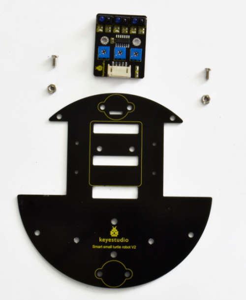
Insert two M3*6MM round-head screw into the tracking sensor, then tighten two M3 Nuts to the screws.
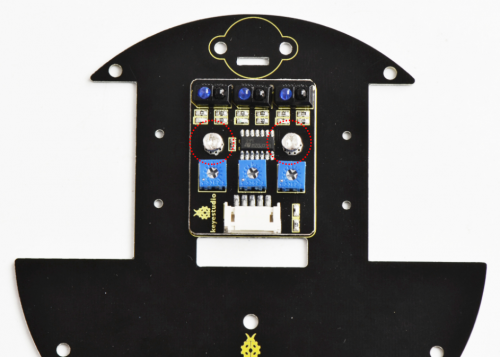
Back view:
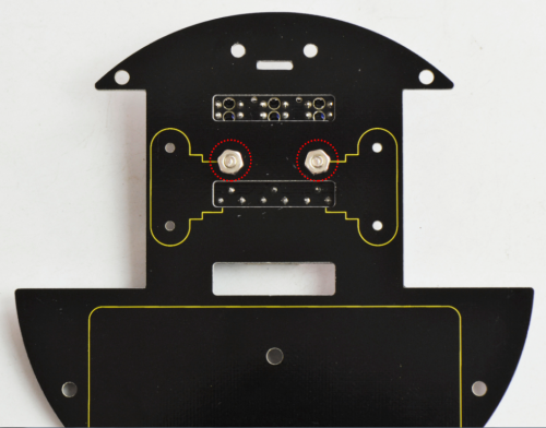
Then fix the two universal casters to the bottom PCB board.
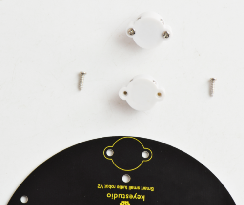
Well done as below:
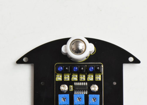
(2) Next, mount the motors on the bottom board. You should first get some parts below:
- U-type holder* 2
- M2*12MM round-head screws *4
- M2 Nut *4
- Motor *2
Note: Now you can check the label A,B on the motor panel.
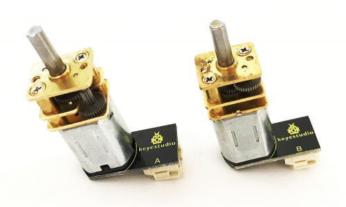
Firstly place four M2 Nuts inside the holes of white N20 motor holders. You should get it as below.
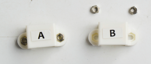
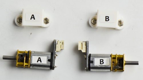
Then place the white holders onto the motors.
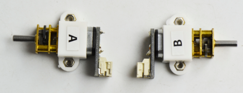
After that, fix these two motor connectors on the bottom PCB with four M2*12MM round-head screws.
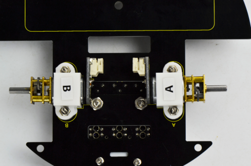
Back view:
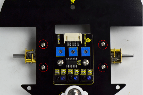
(3) Completed the above assembly, let's install the wheels for this small car.
- wheel *2
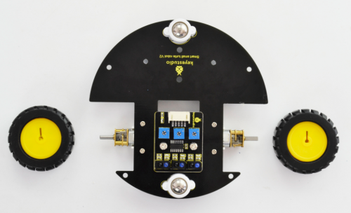
Directly plug the two yellow wheels into the motor shaft. You get it as below.
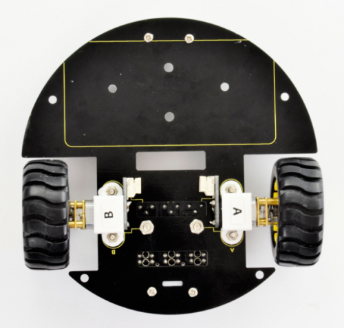
(4) Completed the above assembly, let's install the battery case. You should get all the installed parts as below.
- M3*6MM round-head screws *2
- M3 Nut *2
- Battery case *1
- 18650 Batteries ( not included) *2
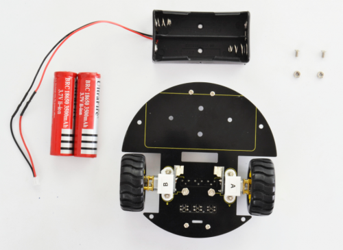
We have provided you with two kinds of battery case. Here we install the 18650 2-cell battery case for the robot. So we will take the turtle robot installed with 18650 battery case as example to start the following project sections.
Firstly you can install the 2-cell AA battery case to the bottom PCB with two M3*6MM round-head screws and M3 nuts as below.
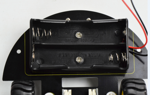
Then insert well the batteries.
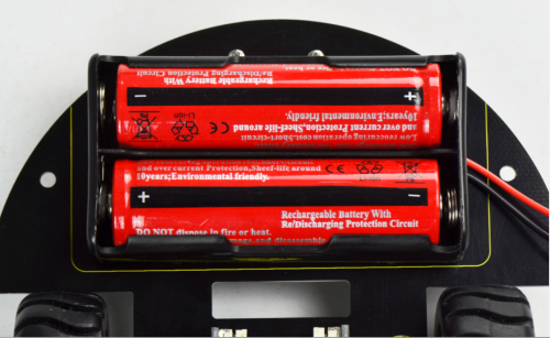
If you prefer to install another 4-cell AA battery case, please see below.
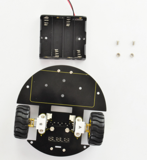
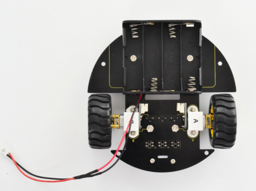
Completed the above steps, you should get prepared for wire connection of motors and tracking sensor below.
- JST-PH2.0MM-2P 24AWG black-red wire 160mm*2
- JST-PH2.0MM-5P 24AWG blue-green-yellow-red-black wire 15CM *1
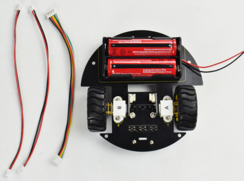
Separately connect the 2P black-red wire 160mm to the motor A and B below.
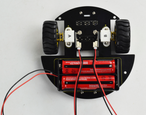
Then connect the 5P blue-green-yellow-red-black wire 15CM to the tracking sensor below.
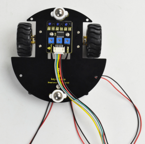
(5) Above parts are installed well, start to install the top parts for the robot.
you should get these components as follows:
- Top PCB *1
- M3 Nut *1
- M3*6MM round-head screws *9
- M3*10MM dual-pass copper pillar *8
- IR receiver sensor *1
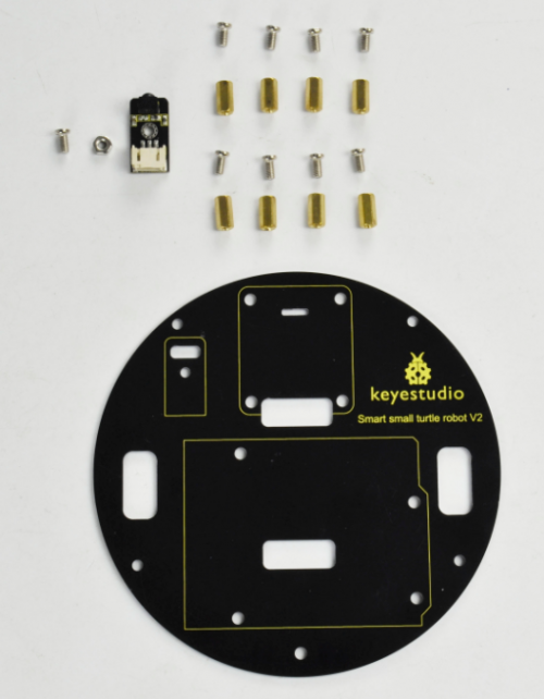
According to the silk mark of bottom PCB, install the IR receiver to the PCB using a M3 nut and a M3*6MM round-head screw. Then screw 8 dual-pass copper pillars to the PCB with 8 M3*6MM round-head screws.
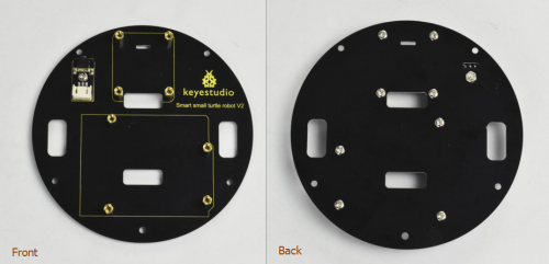
Followed by assembling the control board on bottom PCB. Prepare well the components below:
on bottom PCB. Prepare well the components below:
- Motor drive shield*1
- UNO R3 board*1
- M3*6MM round-head screws *4
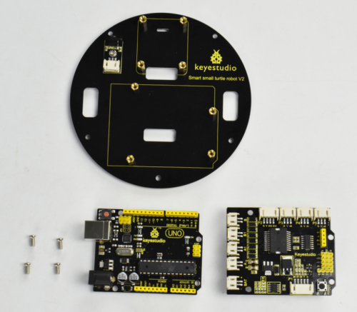
First of all, tighten the UNO board to the PCB using four M3*6MM round-head screws.
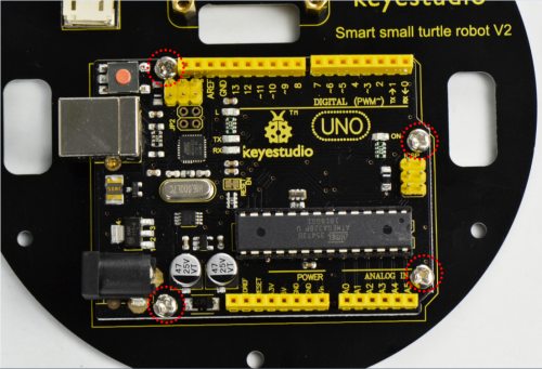
Then simply stack the drive shield onto the UNO R3.
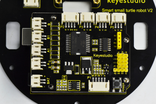
(6) Time to assemble the motor and plastic platform:
- black plastic platform *1
- M1.2*5 tapping screws *4
- Servo *1
- cross white mount *1
- M2*8 screw *1
mount the servo to the black plastic platform with four M1.2*5 tapping screws(included in plastic platform), a cross white mount and a M2*8 screw (included for servo)
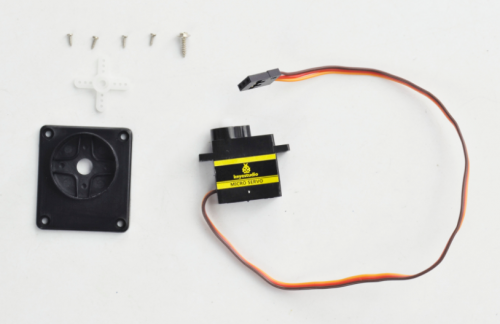
Firstly upload the code to UNO R3 to control the servo rotate to 90 degrees. Detailed method please refer to the project 3 micro servo control mentioned below.
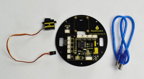
Then fix the cross white mount to the black plastic platform with four M1.2*5 tapping screws.
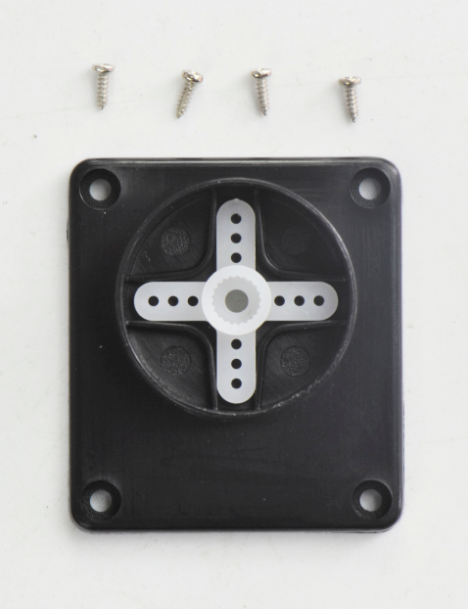
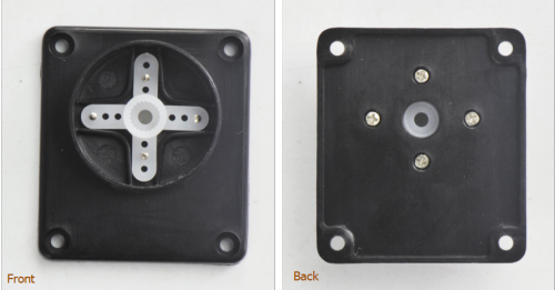
Then adjust the servo towards front in 90 degrees to install it.
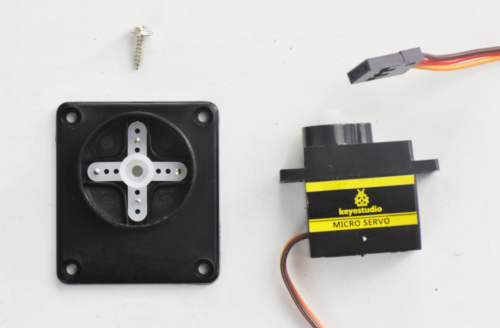
After that, fix the servo to the plastic platform using a M2*8 screw.
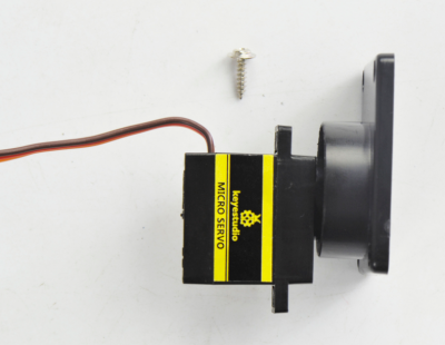
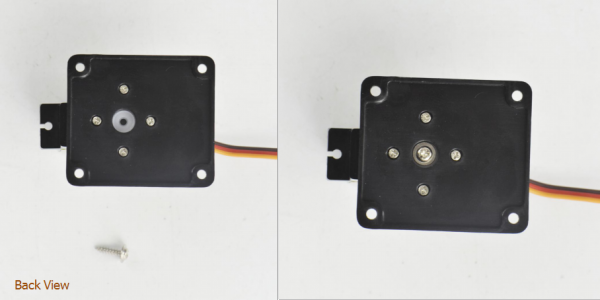
Finally, mount well another two plastic platform holders using two M2*8 screws.
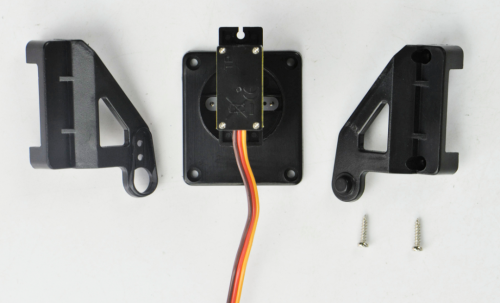
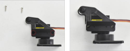
(7) Until now, let’s install the ultrasonic sensor to Servo platform part.
- ultrasonic sensor *1
- JST-PH2.0MM-4P wire 8CM *1
- Nylon cable ties*2
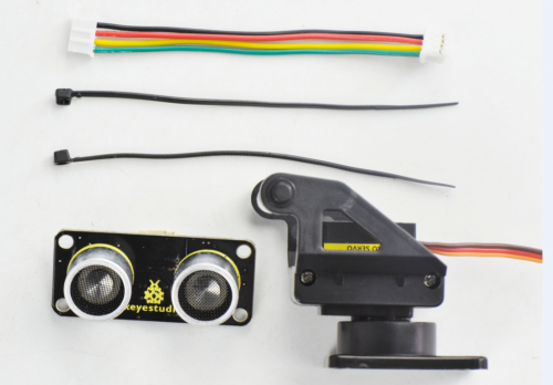
Simply connect the wire to ultrasonic sensor, and then tighten the ultrasonic sensor to the black plastic platform using two cable ties through the holes of sensor.
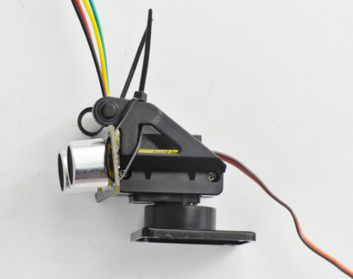
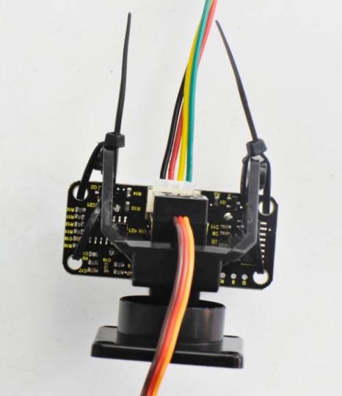
Next, mount them onto the top PCB like below.
For the top PCB, first connect the tracking sensor to the drive shield using a JST-PH2.0MM-3P yellow-red-black wire 8CM.
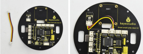
After that, mount the ultrasonic platform part onto the top PCB with four M3*6MM round-head screws. Then connect well one end of the wire connected to ultrasonic sensor to the drive shield.
- Top PCB part
- Ultrasonic platform part
- M3*6MM round-head screw*4
(8) Completed the above assembly, let's install the dot matrix display for this small turtle.
- Dot matrix display *1
- Jumper wire *4
- M3*6MM round-head screws *4
- M3*40MM dual-pass copper pillar* 4
Firstly, connect the jumper wires to the four pins of matrix display.
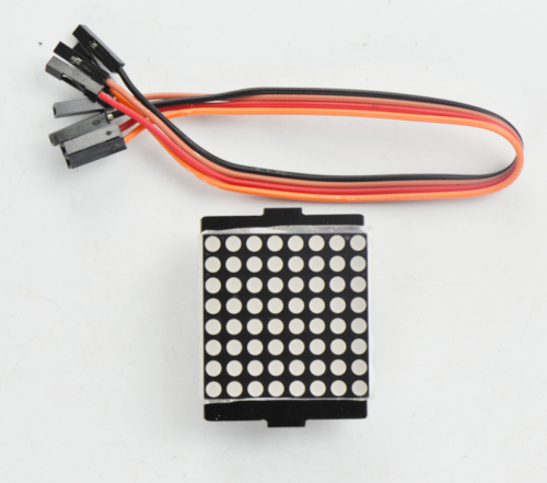
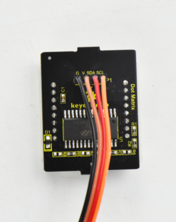
Then screw the four M3*40MM copper pillars to the bottom PCB with four M3*6MM round-head screws.
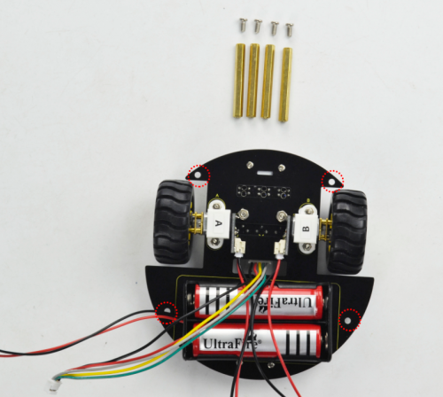
After that, assemble the bottom PCB parts, 8*8 dot matrix display and top PCB parts together using four M3*6MM round-head screws.
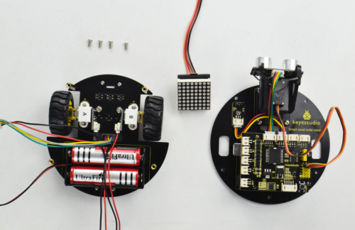
Plug the matrix display into the bottom PCB.
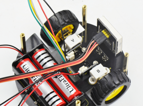
Finally screw the top PCB to the bottom PCB with four M3*6MM round-head screws.
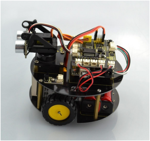
Hookup Guide:
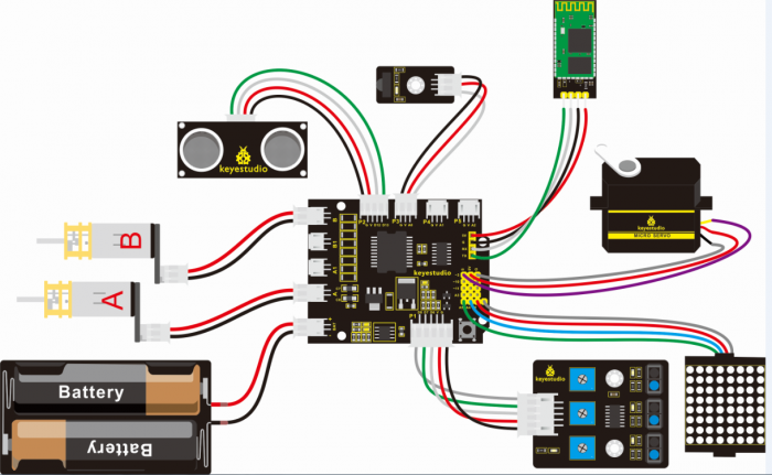
Congrats! The whole turtle robot is installed well.
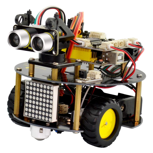
Project Details for Turtle Robot
Project 1: Getting Started with ARDUINO
1)UNO Control Board
When it comes to using the UNO R3 as core of our robot, the UNO is the best board to get started with electronics and coding. If this is your first experience tinkering with the platform, the UNO is the most robust board you can start playing with.
Well, let's at first have a look at this UNO R3 board.
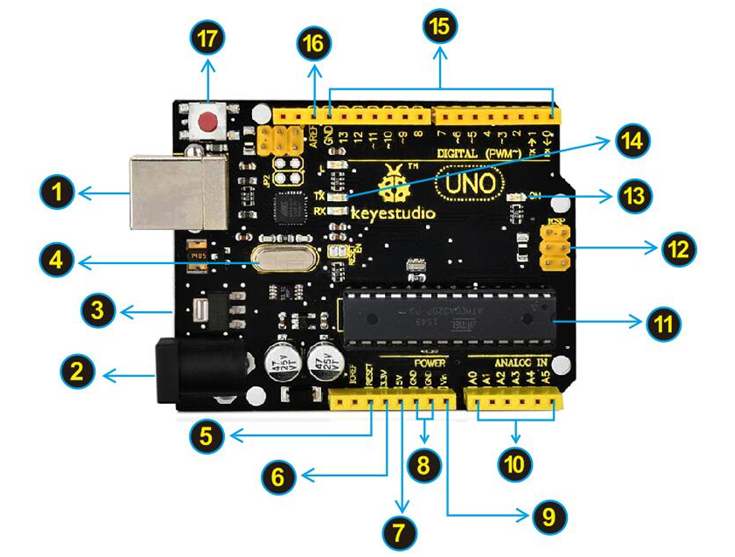
Installing Arduino IDE
When you get the UNO development board, first you should install the software and driver of Arduino. You can see all the Arduino software versions from the link below:
https://www.arduino.cc/en/Main/OldSoftwareReleases#1.5.x
Or you can browse the ARDUINO website at this link, https://www.arduino.cc, pop up the following interface.
Then click the SOFTWARE on the browse bar, you will have two options ONLINE TOOLS and DOWNLOADS.

Click DOWNLOADS, it will appear the latest software version of ARDUINO 1.8.5 shown as below.
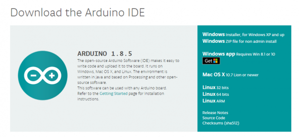
In this software page, on the right side you can see the version of development software for different operating systems. So ARDUINO has a rather powerful compatibility. You should download the software that is compatible with the operating system of your computer.
In our project, we will take WINDOWS system as an example here. There are also two options under Windows system, one is installed version, the other is non-installed version.
For simple installed version, first click Windows Installer, you will get the following page.

This way you just need to click JUST DOWNLOAD, then click the downloaded file to install it.
For non-installed version, first click Windows ZIP file, you will also get the pop-up interface as the above figure.
Click JUST DOWNLOAD, and when the ZIP file is downloaded well to your computer, you can directly unzip the file and then click the icon of ARDUINO program to start it.
Installing Arduino (Windows)
Install Arduino with the exe. Installation package
Click“I Agree”to see the following interface.
Click “Next”. Pop up the interface below.
You can press Browse… to choose an installation path or directly type in the directory you want.
Then click “Install” to initiate installation.
Wait for the installing process, if appear the interface of Window Security, just continue to click Install to finish the installation.
All right, up to now, you have completed the Arduino setup! The following icon will appear on your PC desktop.
Double-click the icon of Arduino to enter the desired development environment shown as below.
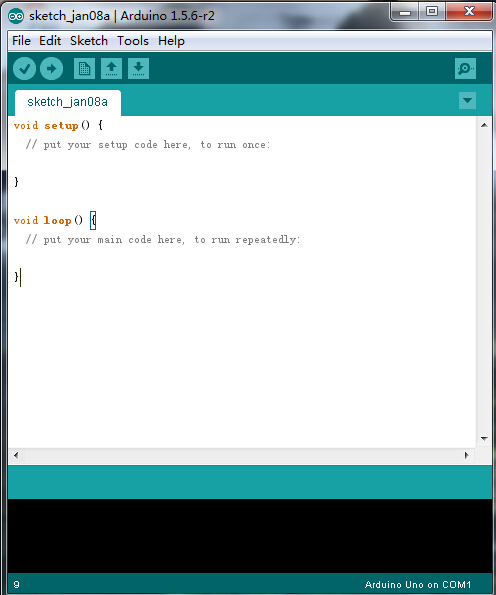
Installing Driver
Next, we will introduce the driver installation of UNO R3 development board. The driver installation may have slight differences in different computer systems. So in the following let’s move on to the driver installation in the WIN 7 system.
The Arduino folder contains both the Arduino program itself and the drivers that allow the Arduino to be connected to your computer by a USB cable. Before we launch the Arduino software, you are going to install the USB drivers.
Plug one end of your USB cable into the Arduino and the other into a USB socket on your computer.
When you connect UNO board to your computer at the first time, right click the icon of your “Computer” —>for “Properties”—> click the “Device manager”, under “Other Devices”, you should see an icon for“Unknown device” with a little yellow warning triangle next to it. This is your Arduino.
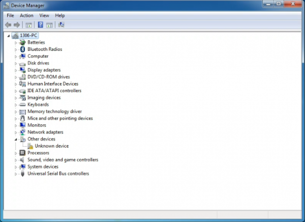
Then right-click on the device and select the top menu option (Update Driver Software...) shown as the figure below..
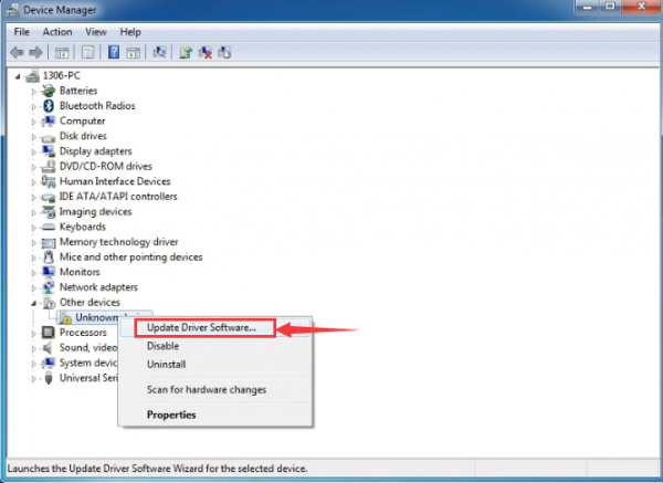
It will then be prompted to either “Search Automatically for updated driversoftware” or “Browse my computer for driver software”. Shown as below. In this page, select “Browse my computer for driver software”.
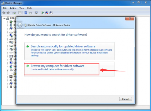
After that, select the option to browseand navigate to the “drivers” folder of Arduino installation.
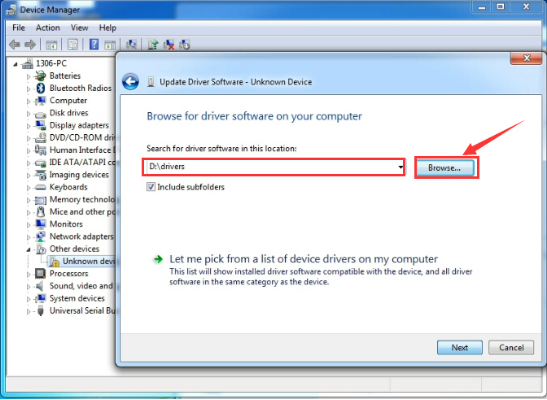
Click “Next” and you may get a security warning, if so, allow the software to be installed. Shown as below.
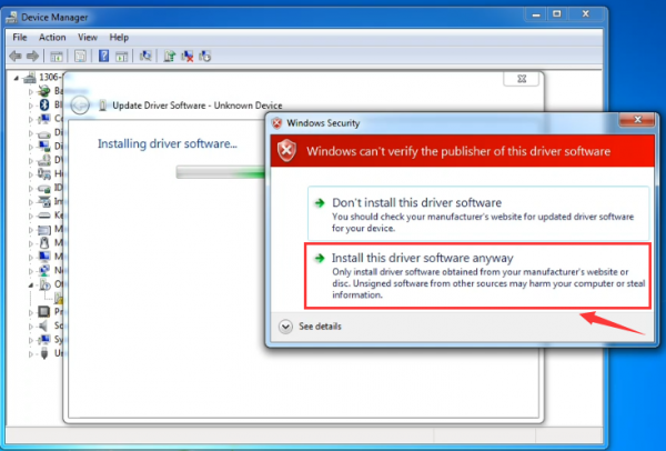
Once the software has been installed, you will get a confirmation message. Installation completed, click “Close”.
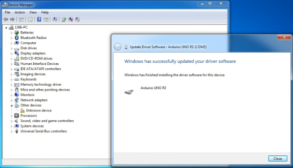
Up to now, the driver is installed well. Then you can right click “Computer” —>“Properties”—>“Device manager”, you should see the device as the figure shown below.
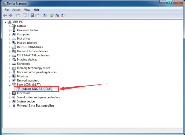
2) Example Use of ARDUINO IDE
STEP 1: Open Arduino
In the previous, we have introduced the driver installation of UNO R3 development board. So this time let’s first have basic understanding of the development environment of ARDUINO. After that, you will learn how to upload the program to Arduino board.
First of all, open the unzipped folder of ARDUINO development software and click icon of ARDUINO to open the software, as the figure shown below.
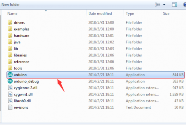
STEP 2: Build Projects
When open the Arduino software, you will have two options as below:
- Build a new project
- Open an exiting project example
If you want to build a new project, please select “File”→then click “New”, you will see the software interface as follows.
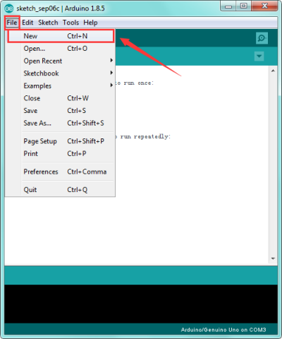
![]()
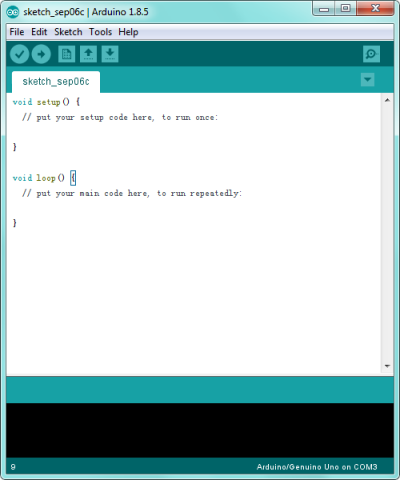
If you want to open an example project, please select File→Example→Basics→Blink. Shown below.
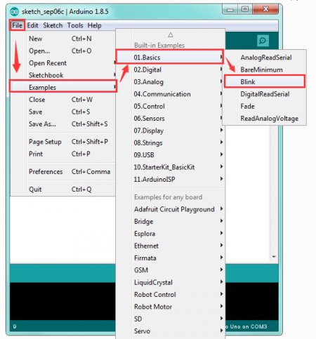
![]()
STEP 3: Select Arduino Board
On the Arduino software, you should click Tools→Board , select the correct board. Here in our tutorial we should select Arduino Uno. Shown as below.
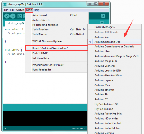
STEP 4: Select Serial Port
If you are not sure which port is correct, at first directly open the Control Panel of your computer, then click to open Device Manager, you can check the COM port here. Shown as below.

Then you should click Tools→Serial Port. It may be COM3 or higher (COM1 and COM2 are usually reserved as hardware serial port).
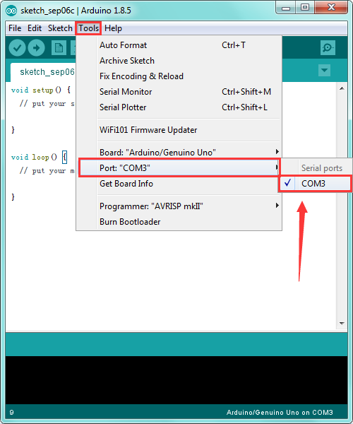
STEP 5: Upload the Code to Your Board
Before showing you how to upload the code to your board, first of all let me introduce the function of each icon on the Tool bar of Arduino IDE. Look at the picture showed below.
![]()
3) Light up an LED
Overview:
In the above section, you have learned how to use the development software. So want to try it out with an example project? Get started with one more basic program, bringing you enter the wonderful programming world of ARDUINO. Great, follow the project sections below to have your first awesome try!
LED experiment is one of the more basic experiments in learning ARDUINO. Here we will use our keyestudio LED module. On the module, you will see a light emitting diode (LED), which has two states of on and off. Since our module itself has done well the circuit, you can use it in a simple way. Just need to connect its pins.
There are three lead-out pins on the module, respectively negative pin(marked -), positive pin(marked +) and signal pin(marked S). Note that the modules from different manufactures may have different pin labels.
Next, connect the three pins of LED module to keyestudio UNO R3 shield using three dupont jumper wires. Connect negative pin to the ground, positive pin to 5V, and signal pin to Digital 11. Shown as below.
Connect It Up:
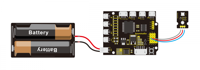
Test Code 1:
int ledpin=11; // define the LED pin as Digital 11
void setup()
{  pinMode(11, OUTPUT); // initialize digital pin 11 as an output.
}
void loop()
 {
  digitalWrite(11, HIGH);   // turn the LED on (HIGH is the voltage level)
  delay(1000);              // wait for a second
  digitalWrite(11, LOW);    // turn the LED off by making the voltage LOW
  delay(1000);              // wait for a second
}
Note:
In the code pay attention to Single line comment (//),so that your can know how your program works.
Comments are lines in the program that are used to inform yourself or others about the way the program works. They are ignored by the compiler, and not exported to the processor, so they don’t take up any space in the microcontroller’s flash memory. Comments' only purpose is to help you understand (or remember), or to inform others about how your program works.
What you should see?
Done wiring, compile the code and then click on the 'Upload' button. The second button from the left on the toolbar of Arduino IDE. When upload well the code to the board, you will see the status at the bottom of window will change to “Done uploading”.
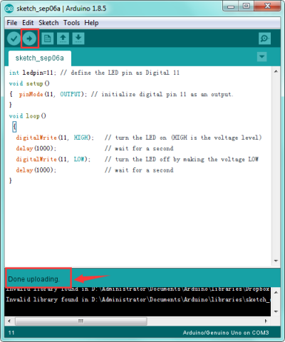
Eventually, you will see the LED light up for one second, then off one second. Congrats! Your first programming is done successfully.
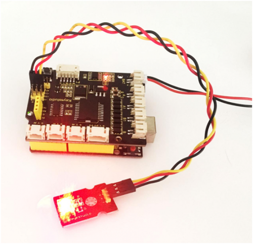
4) PWM Controlled Brightness
Overview:
In the previous project, you have learned how to turn on or off an LED. So you may be interested in changing the brightness of an LED light, just making it like the bedside lamp in your bedroom.
It is indeed important for you to master the knowledge of PWM. Right, PWM is short for Pulse Width Modulation. How can it be understood in a simple way? We all know that the voltage output of Arduino Digital port only has two states, LOW and HIGH, corresponding to the voltage output of 0V and 5V.
If merely make use of LOW and HIGH state, it cannot control the brightness of an LED light. However, if convert the voltage output of 0 Volts and 5 Volts into the value within 0-255, this way you can change the value within 0-255 to control the brightness of light. It is much more feasible, isn’t it ?
Pulse Width Modulation, or PWM, is a technique for getting analog results with digital means. Digital control is used to create a square wave of different duty cycle, a signal switched between on and off. This on-off pattern can simulate voltages in between full on (5 Volts) and off (0 Volts) by changing the portion of the time the signal spends on versus the time that the signal spends off.
The Arduino controller has totally 6 PWM outputs, which are Digital 3, 5, 6, 9, 10 and 11. Shown as follows.
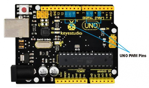
These pins can be used as Digital output or Analog output. If used as Analog output, it needs to call the analogWrite() function of ARDUINO, and this analogWrite() function can be controlled in the range of 0-255.
In the graphic below, the green lines represent a regular time period. This duration or period is the inverse of the PWM frequency. In other words, with Arduino's PWM frequency at about 500Hz, the green lines would measure 2 milliseconds each. A call to analogWrite() is on a scale of 0-255, such that analogWrite(255) requests a 100% duty cycle (always on), and analogWrite(127) is a 50% duty cycle (on half the time) for example.
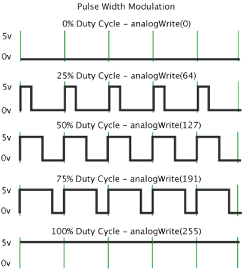
In fact, PWM can be applied to dimming lamps, motor speed, sound production, etc.
In the following, we are going to control the brightness of the LED.
Hookup Guide:
On the aspect of hardware, we still utilize the LED connected to D11 mentioned above. You can refer to the wiring diagram as follows:
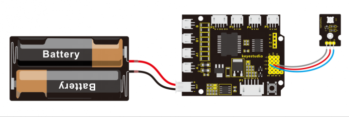
Sample Code 2:
int LED= 11;//define the LED pin
int i = 0;//define a variable i,
void setup(){
pinMode(LED,OUTPUT); //set LED pin as OUTPUT
}
void loop(){
for(i = 0;i < 255;i++){ //variable is changed from 0 to 254(fade in)
analogWrite(LED, i);//set LED brightness
delay(10);//delay 10ms, analogWrite function will be finished in a short time.
//speed is too fast to observe
}
for(i =255;i > 0; i--){ //variable is changed from 255 to 1(fade out)
analogWrite(LED, i);//set LED brightness
delay(10); //delay 10ms
}
}
Code Explanation:
analogWrite(LED, i);
Writes an analog value (PWM wave) to a pin. Can be used to light a LED at varying brightnesses or drive a motor at various speeds. After a call to analogWrite(), the pin will generate a steady square wave of the specified duty cycle until the next call to analogWrite() (or a call to digitalRead() or digitalWrite()) on the same pin. The frequency of the PWM signal on most pins is approximately 490 Hz.
Syntax: analogWrite(pin,value)
It has two parameters:
- pin: the pin to write to. Allowed data types: int.
- value: the duty cycle: between 0 (always off) and 255 (always on). Allowed data types: int
Example Result:
Upload the above code to the board, you could change the LED brightness in the code.

Furthermore, in the motor driving project below, it also involves the concept PWM.
5) Light up LED Matrix
Overview:
In the previous project, we have simply tested the LED. Now we have added a new 8*8 Dot Matrix module to the turtle to show the robot states. Amazing display!
Do you know how is the cool advertising display made? It is exactly composed of these small LED matrix. If you want to make a similar display, this keyestudio 8*8 Dot Matrix module will meet you need.
This tiny display has 64 LEDs packed into a 8*8 dot matrix. It integrated HT16K33as driver chip, so with this LED matrix module, you can control it through connecting the I2C communication interfaces ( A4-SDA ; A5-SCL).
It is great for displaying image/text or creating bizarre patterns, and is highly portable and convenient to use. Of course you can program it via IDE or via Mixly block. With just a few steps, you are ready to impress others!
Hookup Guide:
Connect the LED matrix module to the pin header on the motor drive shield. Connect the SCL pin to pin A5, SDA pin to pin A4; Connect VCC pin to 5V, GND to ground.

Sample Code 3:
#include <Wire.h>
#include "Adafruit_LEDBackpack.h"
#include "Adafruit_GFX.h"
Adafruit_LEDBackpack matrix = Adafruit_LEDBackpack();
void setup() {
  Serial.begin(9600);
  Serial.println("HT16K33 test");

  matrix.begin(0x70);  // pass in the address
}

void loop()
{
  /////////smile face///////////////
    matrix.displaybuffer[0] = B00000011;
    matrix.displaybuffer[1] = B10000000;
    matrix.displaybuffer[2] = B00010011;
    matrix.displaybuffer[3] = B00100000;
    matrix.displaybuffer[4] = B00100000;
    matrix.displaybuffer[5] = B00010011;
    matrix.displaybuffer[6] = B10000000;
    matrix.displaybuffer[7] = B00000011;
    matrix.writeDisplay();
}
Code To Note:
In the code, it needs to call three libraries, that is Wire.h; Adafruit_LEDBackpack.h and Adafruit_GFX.h
Wire.h is a built-in library of Arduino IDE, so not need to add it, but you should place the libraries folder Adafruit_LEDBackpack.h and Adafruit_GFX.h inside the libraries directory of IDE.
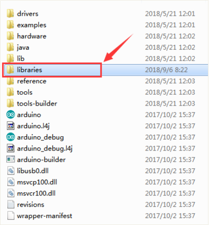
Note: place well the libraries folder, need to reopen the Arduino IDE again, and the libraries should be effective.
You can download the libraries from the link below:
https://drive.google.com/open?id=16ii-ZQTNK_Fn8KG81rhBw7JX1zQQ6nG6
Place the LED matrix as the right picture shown.
In the experiment, you can control the LED dot matrix display through the code matrix.displaybuffer[0] = B00000011
Note: the number 0 in the matrix.displaybuffer[0] represents the columns of LED. The number 0 is the first column, and the number 1 represents the second column. The rest can be done in the same manner.
B00000011 represents the on and off state of 8 LEDs in the cols. The number 0 represents off, while the number 1 represents on.
So matrix.displaybuffer[0] = B00000011 means that the first column, the LEDs in the row 1, 8, 7, 6, 5, 4 are set to off, the LEDs in the row 3 and 2 are on.
What you should see?
Hookup well and upload the code to the board, you should see the keyestudio 8*8 Dot matrix show a smile face.
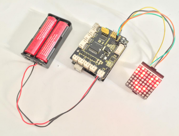
Project 2: Line Tracking Turtle
1) Principle and Application of Line Tracking Sensor
Overview:
The tracking sensor is actually an infrared sensor. The component used here is the TCRT5000 infrared tube.
Its working principle is to use the different reflectivity of infrared light to the color, then convert the strength of the reflected signal into a current signal.
During the process of detection, black is active at HIGH level, but white is active at LOW level. And detection height is 0-3 cm.
The following figure is our keyestudio 3-channel line tracking module. We have integrated 3 sets of TCRT5000 infrared tube on a single board, which is more convenient for wiring and control.
By rotating the adjustable potentiometer on the sensor, it can adjust the detection sensitivity of the sensor.
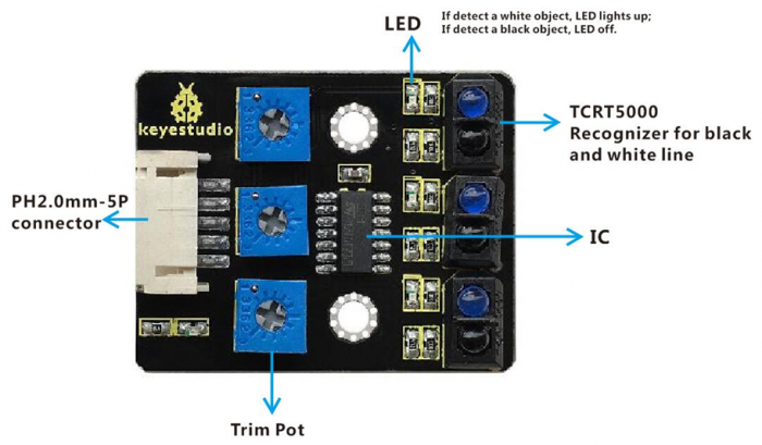
TECH SPECS:
- Operating Voltage: 3.3-5V (DC)
- Interface: 5PIN
- Output Signal: Digital signal
- Detection Height: 0-3 cm
Wiring Diagram:
Okay, next let’s do a simple test for this tracking module.
Connect the line tracking module to the shield using connector wire. Then connect the LED module to the pin11 header on the shield. The connection diagram is shown as below.
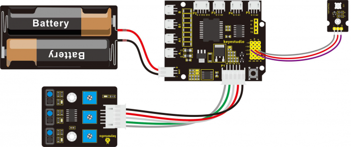
Wire it up well as the above diagram, then you can type the following test code.
Test Code 4:
int sensor1 = 6; // define the pin of left sensor as pin D6
int ledPin =11; //define LEDpin as Digital 11
void setup()
{
    pinMode(sensor1, INPUT); //define the sensor as INPUT
    pinMode(ledPin,OUTPUT); //define LED as OUTPUT
}

void loop()
{
  if( digitalRead(sensor1)==LOW)  // read the state of sensor, if detect the white paper, it is at LOW level.
    {digitalWrite(ledPin, HIGH);  // light an LED
  }
   else // or else
   {
      digitalWrite(ledPin, LOW); // turn off an LED
  }
}
So how do you think about that? It is really simple. For another two-channel, you can refer to the above code to finish the testing.
Test Code 5:
int sensor2 = 7; // define the pin of middle sensor as pin D7
int ledPin =11; // define LEDpin as Digital 11
void setup()
{
    pinMode(sensor2, INPUT); // define the sensor as INPUT
    pinMode(ledPin,OUTPUT); // define LED as OUTPUT
}
void loop()
{
   if( digitalRead(sensor2)==LOW)  // read the state of sensor, if detect the white paper, it is at LOW level.
    {digitalWrite(ledPin, HIGH);  // light an LED
  }
   else //or else
   {
      digitalWrite(ledPin, LOW); // turn off an LED
  }
}
Test Code 6:
int sensor3 = 8; //  define the pin of right sensor as pin D8
int ledPin =11; // define LEDpin as Digital 11
void setup()
{
    pinMode(sensor3, INPUT); // define the sensor as INPUT
    pinMode(ledPin,OUTPUT); // define LED as OUTPUT
}

void loop()
{
if( digitalRead(sensor3)==LOW)  //read the state of sensor, if detect the white paper, it is at LOW level.
    {digitalWrite(ledPin, HIGH);  // light an LED
  }
   else // or else
   {
      digitalWrite(ledPin, LOW); // turn off an LED
  }
}
Upload well the code to the board, you should see that if the tracking sensor detects a white object, the LED module will light up.
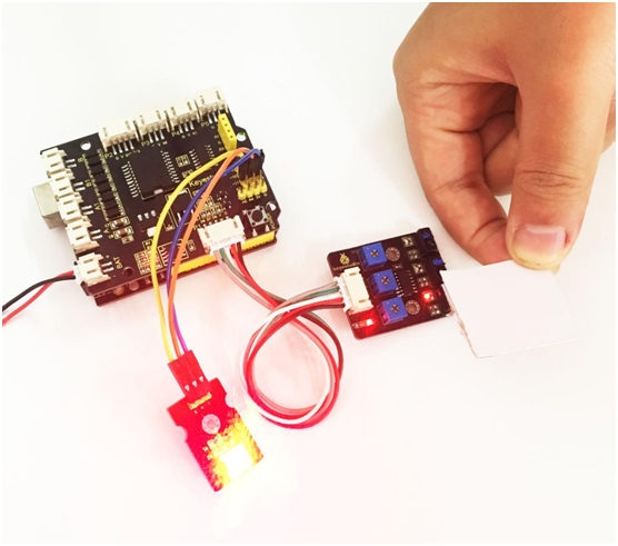
In the section below, we are about to match the digital sensors with other modules to make interactive works.
2) Motor Driving and Speed Control
Overview:
There are many ways to drive the motor. Our robot uses the most commonly used L298P solution.
L298P is an excellent high-power motor driver IC produced by STMicroelectronics. It can directly drive DC motors, two-phase and four-phase stepping motors.
The driving current up to 2A, and output terminal of motor adopts eight high-speed Schottky diodes as protection. We have designed the motor driver shield based on the L298P circuit.
The stackable design can make it be plugged directly into the Arduino, reducing the technical difficulty of using and driving the motor.
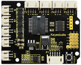
When stack the driver shield onto UNO R3 board, after the BAT is powered on, press the POWER button lightly. The external power will be supplied to both the driver shield and UNO R3 board at the same time.
In order to facilitate wiring, the driver shield comes with an anti-reverse interface. When connecting the motor, power supplyand sensor modules, you just need to plug incorrectly.
The Bluetooth interface on the driver shield is fully compatible with keyestudio HC-06 Bluetooth module. When connecting, you just need to plug HC-06 Bluetooth module into the corresponding interface.
At the same time, thedrive shield solders 2.54mm pin headers tolead outsome unused digital ports and analog ports, so that you can continue to add other sensors for experiments extension.
Specifications:
- 1. Logic part input voltage: 5V
- 2. Driving part input voltage: DC 7-12V
- 3. Logic part working current: <36mA
- 4.Driving part working current: <2A
- 5. Maximum powerdissipation: 25W (T=75℃)
- 6. Control signal input level:
High level: 2.3V<Vin<5V

Low level: -0.3V<Vin<1.5V
- 7. Working temperature: -25℃~+130℃
Pinout Instructions:
As the diagram shown below, you can get the detailed information of connectors on the motor drive shield.
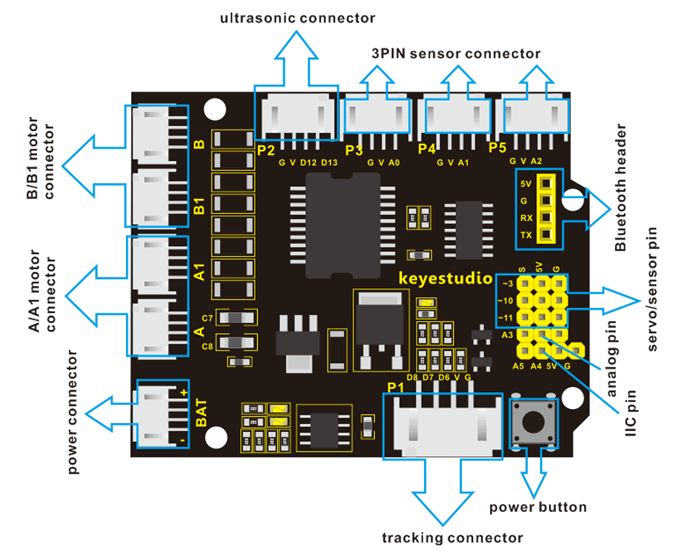
Driving DC Motor:
In the previous section, we have shown you the basic principle and parameters of L298P motor drive module. You can get the details of all interfaces on the board. So in the following, we will formally introduce how to drive the motor? First, you should connect well two motors to the shield, i.e. motor A and motor B shown as below.
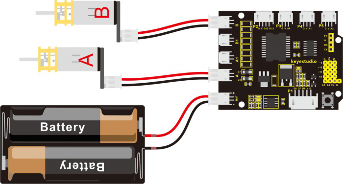
Well, next let’s create the sketch.
The code logic of the robot is nothing more than 5 kinds of movement modes, namely go forward, go backward, turn left, turn right and stop. So think about it. How could it implement those functions?
Simply, for example, both left and right motor of robot turn forward, so it is able to go forward. If both the left and right motor turn reverse, the robot will go backward.
Besides, if the left motor turns forward but right motor turns reverse, the robot will turn right. If the right motor turns forward but left motor turns reverse, the robot will turn left.
So how to control the forward and backward of motor? Actually, you can easily achieve that by controlling the microcontroller pin for motor direction to be HIGH or LOW level.
It is much more easier to understand the motor turning, however, it would be a little bit complicated to work out the speed control of motor.
As for the speed control of motor, it involves the PWM mode mentioned in the previous section. So what is PWM?
PWM is the short for Pulse Width Modulation. PWM is a technique for getting analog results with digital means. Digital control is used to create a square wave (a signal switched between on and off) to control the analog output. The output voltage of Arduino Digital port only has LOW and HIGH level, corresponding to the output voltage of 0 Volts and 5 Volts.
Like the graphic shown below, the green lines represent a regular time period. This duration or period is the inverse of the PWM frequency.
In other words, with Arduino's PWM frequency at about 500Hz, the green lines would measure 2 milliseconds each.
A call to analogWrite() is on a scale of 0-255, such that analogWrite(255) requests a 100% duty cycle (always on), and analogWrite(127) is a 50% duty cycle (on half the time) for example.

For example, we have marked the PWM pins that can be used for analog output on the UNO board.
The PWM pins are D3, D5, D6, D9, D10, and D11.

The function called by the PWM is: analogWrite(pin, value).
Note that the value is between 0 (always off) and 255 (always on). The speed of the motor is controlled actually by this value. The bigger the value is, the faster the speed is. Rather, the smaller the value is, the slower the speed it is until it stops.
In the following figure, look at the language logic for motor states: go forward, backward, turn left, turn right and stop.
M1 and M2 represent the motor’s direction control, that is, forward and backward rotation.
E1 and E2 represent the speed control, and speed is set to 150.
| E1 | M1 | E2 | M2 | |||
|---|---|---|---|---|---|---|
| Forward | 150 | HIGH | Motor A goes forward | 150 | HIGH | Motor B goes forward |
| Backward | 150 | LOW | Motor A goes backward | 150 | LOW | Motor B goes backward |
| Left | 150 | LOW | Motor A goes forward | 150 | HIGH | Motor B goes backward |
| Right | 150 | HIGH | Motor A goes backward | 150 | LOW | Motor B goes forward |
| Stop | 0 | LOW | Motor A stops | 0 | LOW | Motor B stops |
Example Code 7:
Okay, next we will start to write the example code. The part of Single line comment (//) is the explanation for the code. Based on that, you can understand it better.
int E1 = 9; //  set the speed pin of motor A as D9
int E2 = 5; //  set the speed pin of motor B as D5
int M1 = 2; // set the direction pin of motor A as D2
int M2 = 4; // set the direction pin of motor B as D4

void setup(void)
{
  pinMode(M1,OUTPUT); // set M1 as OUTPUT mode
  pinMode(M2,OUTPUT); // set M2 as OUTPUT mode
  pinMode(E1,OUTPUT); //  set E1 as OUTPUT mode
  pinMode(E2,OUTPUT); //  set E2 as OUTPUT mode
}
void advance(void)        // set the forward motion
{
  digitalWrite(M1,HIGH);  // motor A turns forward, the wheel will go forward.
  digitalWrite(M2,HIGH);  // motor B turns forward, the wheel will go forward.
  analogWrite(E1,150);    // speed of motor A(can be adjusted according to the actual speed of motor. Turn up the value to accelerate, lower the value to decelerate.)
  analogWrite(E2,150);    // speed of motor B(can be adjusted according to the actual speed of motor. Turn up the value to accelerate, lower the value to decelerate.)
}
void back(void)        // set the backward motion
{
 digitalWrite(M1,LOW);   // motor A turns reverse and the wheel will go backward
 digitalWrite(M2, LOW);   //  motor B turns reverse and the wheel will go backward
 analogWrite(E1,150);     //  speed of motor A
 analogWrite(E2, 150);    //  speed of motor B
}

void turnL(void)     // set the left turn
{
   digitalWrite(M1,LOW);    // motor A turns reverse and the wheel will go backward
   digitalWrite(M2, HIGH);  // motor B turns forward and the wheel goes forward, the smart car will turn left.
   analogWrite(E1,150);  // speed of motor A
   analogWrite(E2, 150);  // speed of motor B
}

void turnR(void)            //  set the right turn
{
   digitalWrite(M1,HIGH);   // motor A turns forward and the wheel will go forward
   digitalWrite(M2,LOW);    // motor B turns reverse and the wheel goes backward, the smart car will turn right.
   analogWrite(E1,150);     // speed of motor A
   analogWrite(E2, 150);    // speed of motor B
}

void stopp(void)   // set the STOP
{
   digitalWrite(M1,LOW);  // motor A turns reverse
   digitalWrite(M2, LOW);  //  motor B turns reverse
   analogWrite(E1, 0);      //  speed of motor A, speed as zero, means stop
   analogWrite(E2, 0);      // speed of motor B, speed as zero, means stop
}

void loop()
{
advance();   // go forward
delay(1000); // delay1S
back();      //backward
delay(1000);// delay1S

turnL();    //turn left
delay(1000);//delay1S
turnR();    //turn right
delay(1000); //delay1S
stopp();   // stop
delay(1000);// delay1S
}
Test Result:
Stack well the drive shield onto UNO R3 board, and upload the above code to the board, then press down the POWER button, you should see the motor go forward for one second, backward one second, then turn left for one second, turn right for one second and stop one second, alternately repeating.
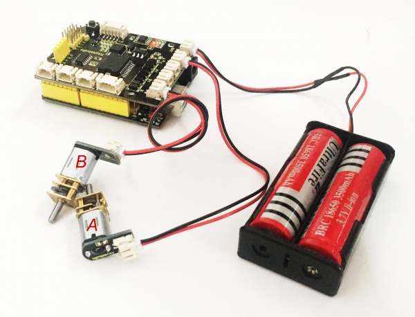
3) Line Tracking Turtle
Project Overview:
In the previous sections, you have learned the principles and applications of both tracking module and the motor drive shield. After master that knowledge, let’s combine these two modules to make the turtle with line tracking function.
So first what does line tracking mean? It refers to following the line trajectory. For instance, the smart robot will always follow or track the black line.
The principle is using the tracking sensor to detect the black track on the pavement, and detection signal will feed back to ARDUINO main control board. Then main control board will analyze and judge the collected signals to control and drive the motor in time, thus can adjust the turning direction of turtle robot.
That is why the turtle robot can automatically follow the black track, achieving the automatic line tracking function.
This technology has been applied to many areas such as driverless vehicles, unmanned factories, warehouses, and service robots.
Project Principle:
Using the characteristic that black has low reflectivity to light.
When flat surface is not black, the infrared light transmitted by the sensor will be reflected back mostly, so the sensor outputs low level 0.
When the flat surface has a black line and the sensor is above the black line, the reflected infrared light is very less due to the weak reflectivity of black, so it does not reach the action level and sensor outputs high level 1.
Use the main control board to determine whether the output end of sensor is 0 or 1, finally detect the black line. The main control board will control the turning direction of motor according to the received signal, so finally can control the movement of smart car. This is a simple line tracking robot.
Wiring Diagram:
Connect the tracking sensor, two motors and battery pack to the motor drive shield as follows.
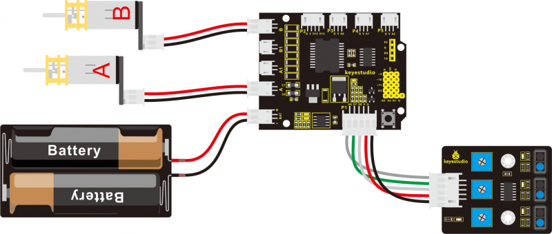
Example Code 8:
Wire it up well as the above diagram. Okay, let’s move on to write the test code. Think about the code logic.
There are two kinds of tracking sensor’s states as follows:
1.The middle tracking sensor detects a black line, if the sensor on the left side detects a white line, while the sensor on the right side detects a black line, the smart car will turn right.
On the contrary, if the sensor on the right detects a white line, but the left one detects a black line, the smart car will turn left. If both sides detect a white line or a black line, it will go forward.
2.The middle tracking sensor does not detect a black line, if the sensor on the left side detects a white line, while the sensor on the right side detects a black line, the smart car will turn right.
On the contrary, if the sensor on the right detects a white line, but the left one detects a black line, the smart car will turn left. If three sensors all detect a white line, it will stop.
Well, figure out the logic, then combine the example code of motor driving mentioned in the above section, you can have a try to write out the logic of line tracking.
#define INT_A 2 // define the left motor direction pin D2
#define INT_B 4 // define the right motor direction pin D4
#define left_A 9 // define the left motor speed(PWM)pin D9
#define right_B 5 // define the right motor speed(PWM)D5

const int S1 = 8;  // S1 right tracking sensor control pin to D8
const int S2 = 7;  // S2 middle tracking sensor control pin to D7
const int S3 = 6;  // S3 left tracking sensor control pin to D6
int s1,s2,s3;   //define three variables, separately receive the digital value read by 3-channel tracking sensor (0 or 1)


void setup()
{
  Serial.begin(9600);    //set the monitor baud rate to 9600
  delay(100);       //delay 100ms
  pinMode(INT_A,OUTPUT);      // set the motor control pin as OUTPUT
  pinMode(INT_B,OUTPUT);
  pinMode(left_A,OUTPUT);
  pinMode(right_B,OUTPUT);
}

void loop()
{
    s1 = digitalRead(S1); //assign the digital value read from pin S1,S2,S3 to s1,s2,s3
    s2 = digitalRead(S2);
    s3 = digitalRead(S3);

    if(s2==1)  //if s2 pin detects a black line
    {
      if(s3==1 && s1==0)  //if s3 pin detects a black line but s1 doesn’t
      {
        left();     // turn left
      }
      else if(s3==0 && s1==1)  //if s3 does not detect a black line, but s1 detects it.
      {
        right();   //turn right
      }
      else      //other situations
      {
        front();   // go forward
      }
    }

    else  //s2 does not detect a black line
    {
      if(s3==1&&s1==0)  //if s3 detects a black line
      {
        left();     //turn left
      }
      else if(s3==0&&s1==1)  //s1 detects a black line
      {
        right();    // turn right
      }
      else  // none detect black line
      {
        Stop();      // stop
      }
    }

}
// forward
void front()
{
  digitalWrite(INT_A,LOW);    // control the left motor turn forward
  digitalWrite(INT_B,LOW);   // control the right motor turn forward
  analogWrite(left_A,200);   // set the motor speed(PWM=200)
  analogWrite(right_B,200);
}
//backward
void back()
{
  digitalWrite(INT_A,HIGH);   // control the left motor turn backward
  digitalWrite(INT_B,HIGH);    // control the right motor turn backward
  analogWrite(left_A,200);
  analogWrite(right_B,200);
}
//turn left
void left()
{
  digitalWrite(INT_A,HIGH);    // control the left motor turn backward
  digitalWrite(INT_B,LOW);    // control the right motor turn forward
  analogWrite(left_A,100);    // motors speed(PWM为100)
  analogWrite(right_B,100);
}
// turn right
void right()
{
  digitalWrite(INT_A,LOW);     // control the left motor turn forward
  digitalWrite(INT_B,HIGH);     // control the right motor turn backward
  analogWrite(left_A,100);
  analogWrite(right_B,100);
}
// stop
void Stop()
{
  digitalWrite(INT_A,LOW);
  digitalWrite(INT_B,LOW);
  analogWrite(left_A,0);    // both side PWM is 0
  analogWrite(right_B,0);
}
Example Picture:
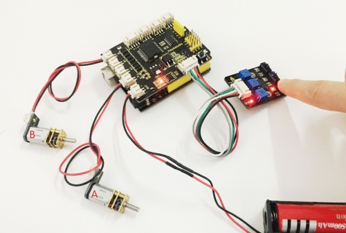
Upload well the above code to the main board, then press down the POWER button on the motor drive shield. If draw a black line on the ground, you should see that the smart car will track the black line.
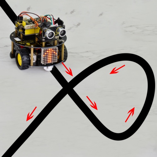
Project 3: Turtle Robot Avoiding Obstacles
1) Principle and Application of Ultrasonic Module
Description:
There is an animal called bat in nature. The bats can fly at night, not depend on its eyes, but on its ears and vocal organs. When the bat flies, it will emit a scream, an ultrasonic signal that humans cannot hear because of its high audio frequency. If these ultrasonic signals hit other objects on the flight path, they will be reflected back immediately. After receive the returned information, the bats complete the whole process of listening, seeing, calculating and bypassing obstacles during the flutter.
The principle of the ultrasonic rangefinder module is as the same as the above principle.
The ultrasonic module will emit the ultrasonic waves after trigger signal. When the ultrasonic waves encounter the object and are reflected back, the module outputs an echo signal, so it can determine the distance of object from the time difference between trigger signal and echo signal.
Ultrasonic sensor has a wide range of sensitivity, no blind area, and no interference with obstacles.
As the following picture shown, it is our keyestudio ultrasonic module. You can see it has two somethings like eyes. One is transmitting end, the other is receiving end.
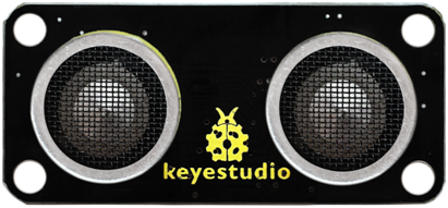
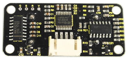
TECH SPECS:
- Operating Voltage: 5V(DC)
- Operating Current: 15mA
- Operating Frequency: 40khz
- Maximum Detection Distance: 3-5m
- Minimum Detection Distance: 3-4cm
- Sensing Angle: less than 15 degrees
Hookup Guide:
Connect the ultrasonic module to the shield. Shown as below.
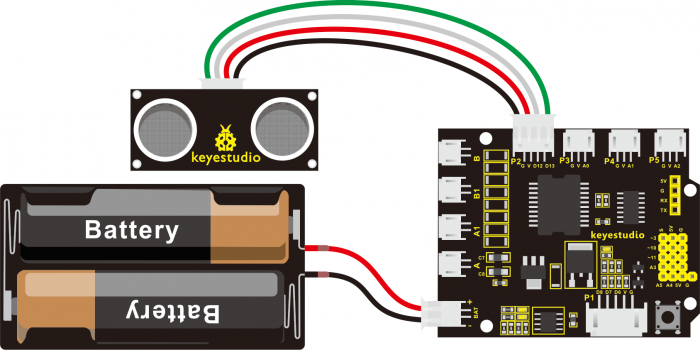
【Notice:】
1.Must first connect the ultrasonic module and then power up. Or connect the ground first.
2.Measurement period is better at more than 60ms. To prevent the impact of the transmitted signal to the echo signal.
When using it:
(1) Use IO trigger ranging, at least 10us HIGH level signal; that is, first pull the Trip Low, then give a HIGH level signal of 10us.
(2) The module automatically sends eight square waves of 40khz to automatically detect whether there is a signal return back;
(3) There is a signal return, through the IO output a High level, and the duration period of High level is the time of Ultrasonic wave from emission to return.
Test distance = (High level time * speed of sound (340M/S))/2
Then you can get the formula: detection distance = (High level time/58)(cm)
Example Code 9:
int pinTrip=12;// connect the SR04 Trip , give more than 10us High level
int pinEcho=13;// connect the Echo pin , the time to receive the High level
float distance=0;// save the distance
void setup() {
// put your setup code here, to run once:
pinMode(pinTrip,OUTPUT);
pinMode(pinEcho,INPUT);
Serial.begin(9600);
}
void loop() {
// put your main code here, to run repeatedly:
digitalWrite(pinTrip,LOW);
delayMicroseconds(2); // pull down Level
digitalWrite(pinTrip,HIGH);
delayMicroseconds(12);// give 12us High level
digitalWrite(pinTrip,LOW);// pull down Level
distance=pulseIn(pinEcho,HIGH);// check the High level time
delay(10);
distance=distance/58; // get the distance
Serial.print("distance=");
Serial.print(distance);
Serial.println("cm");
delay(500);
}
Test Result:
Stack well the shield on UNO R3 board, and upload well the above code, then open the serial monitor of Arduino IDE, set the baud rate to 9600.
When ultrasonic sensor detects an obstacle ahead, on the monitor you should see the distance measured between obstacle and sensor. Shown below.
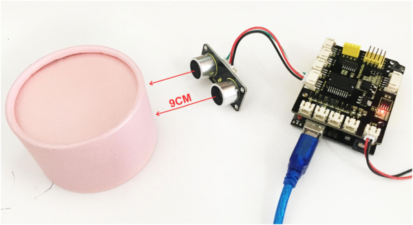
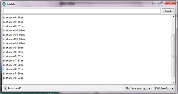
2) Micro Servo Control
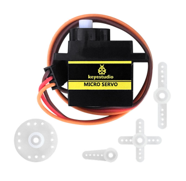
Description:
Servo motor is a position control rotary actuator. It mainly consists of housing, circuit board, core-less motor, gear and position sensor.
Included with your servo motor you will find a variety of white motor mounts that connect to the shaft of your servo. You may choose to attach any mount you wish for the circuit. It will serve as a visual aid, making it easier to see the servo spin.
Working principle:
The receiver or MCU outputs a signal to the servo motor. The motor has a built-in reference circuit that gives out reference signal, cycle of 20ms and width of 1.5ms. The motor compares the acquired DC bias voltage to the voltage of potentiometer and outputs a voltage difference.
Servo motors come with many specifications. But all of them have three connection wires, distinguished by brown, red, orange color (different brand may have different color). Brown one is for GND, red one for power positive, orange one for signal.
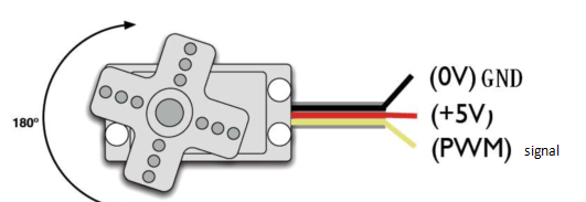
When you send the right signal through the signal wire, the servo will move to a specific angle and stay there. Common servos rotate over a range of about 0° to 180°. The signal that is sent is a PWM signal.
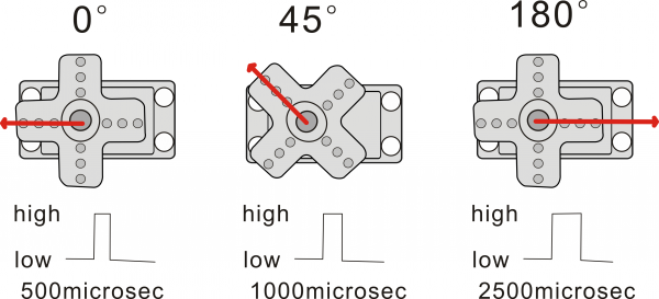
The rotation angle of servo motor is controlled by regulating the duty cycle of PWM(Pulse-Width Modulation) signal. The standard cycle of the PWM signal is 20ms (50Hz). Theoretically, the width is distributed between 1ms-2ms, but in fact, it's between 0.5ms-2.5ms. The width corresponds the rotation angle from 0° to 180°.
Parameters:
- Operating voltage: DC 4.8V〜6V
- Angle range: about 180°(in 500→2500μsec)
- Pulsewidth range: 500→2500μsec
- No-load speed: 0.12±0.01 sec/60(DC 4.8V); 0.1±0.01 sec/60(DC 6V)
- No-load current: 200±20mA(DC 4.8V); 220±20mA(DC 6V)
- Stop torque: 1.3±0.01kg/cm(DC 4.8V); 1.5±0.1kg/cm(DC 6V)
- Stop current: ≦850mA(DC 4.8V); ≦1000mA(DC 6V)
- Standby current: 3±1mA(DC 4.8V); 4±1mA(DC 6V)
- Operation temperature: -10℃〜50℃
- Save temperature: -20℃〜60℃
- Motor wire length: 250 ± 5 mm
- Dimensions: 22.9mm*12.2mm*30mm
- Weight: 9± 1 g (without servo mounts)
Hookup Guide:
Ready to start hooking everything up? Check out the connection diagram below. Connect the black servo to the shield. Brown wire is for GND, red one for 5V pin, orange one for signal pin.

You can check out the test code for the servo below.
Code 10:
int servopin=3;// define the digital 9 is connected to servo signal line
int myangle;// define the angle variable
int pulsewidth;// define the pulsewidth variable
int val;
void setup()
{
pinMode(servopin,OUTPUT);// set the servo interface as OUTPUT
Serial.begin(9600);// connect to serial port, baud rate to 9600
Serial.println("servo=o_seral_simple ready" );
servopulse(servopin,90);// call the pulse function, make the servo rotate to 90degree
}
void loop()
{
  servopulse(servopin,90);// call the pulse function, make the servo rotate to 90degree
}
void servopulse(int servopin,int myangle)// define a pulse function
{
pulsewidth=(myangle*11)+500;// convert the angle into pulse width of 500-2480
digitalWrite(servopin,HIGH);// set the servo pin to HIGH
delayMicroseconds(pulsewidth);// delay the microseconds of pulsewidth
digitalWrite(servopin,LOW);// set the servo pin to LOW
delay(20-pulsewidth/1000);
}
Test Result:
Wire it up and upload well the code, press down the reset button on the shield, micro servo will rotate to the angle of 90 degrees.
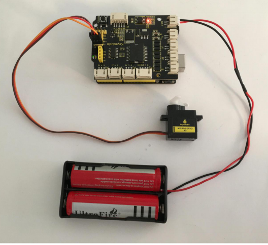
3) Turtle Robot Avoiding Obstacles
Description:
It is rather not suitable for human to work in some relatively harsh environments. At this moment, if we have a robot that can shuttle freely in such environments, then how good should it be!
Based on this original intention, our team develop the robot that be able to automatically avoid an obstacle when running on complicated terrain.
This project is a simple and automatic obstacle avoidance system based on Arduino control board.
The smart robot with UNO R3 as the controlling core, makes use of ultrasonic module and micro servo of 180 degrees to detect the obstacles, and the detection signal will feed back to the control board.
Arduino main board will then analyze and judge the collected signals to control the motordriving in time. Finally control the smart car automatically avoid an obstacle ahead to run forward smoothly.
Project Principle:
- 1. Use the ultrasonic module to detect the distance between the robot and obstacle ahead.
- 2. When the measured distance between ultrasonic sensor and obstacle ahead is less than 15cm, smart robot will stop for 100ms. The ultrasonic will make use of servo to turn left in 90 degrees, and stop for 100ms to detect the obstacle distance on the left. Then use the servo to turn right in 180 degrees, stop to detect the obstacle distance on the right.
- 3. If the distance measured at the left side is greater than that of the right side, ultrasonic sensor will first turn to the front, turtle robot turns left in 90 degrees and then goes forward.
- Otherwise, turtle robot will turn right in 90 degrees and then go forward.
- 4. Arduino control board will control the motor’s rotating direction and servo angle according to the distance value measured by ultrasonic sensor between robot and obstacle.
Wiring Diagram:
Firstly you can follow the connection diagram below.
Connect the ultrasonic module, micro servo and two motors to the drive shield.
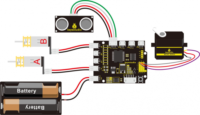
Code 11:
Let’s move on to an example code for the obstacle avoidance robot. You can see the code reference below:
#define INT_A 2    // control the left motor direction pin to D2
#define INT_B 4    // control the right motor direction pin to D4
#define left_A 9    // define the left motor speed as pin D9
#define right_B 5   // define the right motor speed as pin D5
// Ultrasonic
int servopin=3;// digital 3 is connected to servo signal pin
int myangle;// define the angle
int pulsewidth;// define the pulsewidth
#include <SR04.h>    // add the ultrasonic libraries
#define TRIG_PIN 12   // define the pin ting of ultrasonic as D12
#define ECHO_PIN 13   //define the pin echo of ultrasonic as D13
SR04 sr04 = SR04(ECHO_PIN,TRIG_PIN);    // build the ultrasonic object to control the ultrasonic
long a,a1,a2;      // used to receive the distance measured by ultrasonic
void setup()
{
  Serial.begin(9600);  // set the monitor baud rate to 9600
  delay(100);     // delay 100ms
  pinMode(INT_A,OUTPUT);     // set the motor control pin as OUTPUT
  pinMode(INT_B,OUTPUT);
  pinMode(left_A,OUTPUT);
  pinMode(right_B,OUTPUT);
  pinMode(servopin,OUTPUT);// set the servo pin as OUTPUT
  servopulse(servopin,90);  // call the pulse function, make the ultrasonic keep front.
}

void loop()
{
   a=sr04.Distance();    // assign the front distance measured by ultrasonic to a
   Serial.print(a);     // print a value on the monitor
   Serial.println("cm");   // print cm and line wrap
   delay(100);    // delay
   if(a<15)    // whether the distance a is less than 15cm, if yes, then perform the program in the brace.
   {
    Stop();    // car stops
    delay(100);   // delay 100ms
    servopulse(servopin,160);// call the pulse function to make ultrasonic sensor turn left in 90 degrees
    a1=sr04.Distance();  // assign the left obstacle distance measured by ultrasonic to a1
    Serial.print("a1 = ");  // print out the a1 = on the serial monitor
    Serial.print(a1);      //print a1 value
    Serial.println("cm");   // print cm and line wrap
    delay(100);    // delay 100ms
    servopulse(servopin,20);// call the pulse function to make ultrasonic sensor turn right in 90 degrees
    a2=sr04.Distance();      // assign the right obstacle distance measured by ultrasonic to a2
    Serial.print("a2 = ");
    Serial.print(a2);
    Serial.println("cm");
    delay(100);
    if(a1>a2)     // whether a1 is greater than a2(whether left distance is greater than that measured on the right side.)
    {
      servopulse(servopin,90);// call the pulse function, make the ultrasonic keep front.
      left();    //turn left
      delay(370);   // delay370ms,the time for car to turn left in 90 degrees as much as possible.
      front();  // go front
    }
    else     // if a1<a2
    {
      servopulse(servopin,90);  // call the pulse function, make the ultrasonic keep front.
      right();  // turn right
      delay(370);  // delay 370ms,the time for car to turn right in 90 degrees as much as possible.
      front();   // the car goes forward
    }
   }
   else   // if a>15cm
   {
    front();   //the car goes forward
   }

}

// forward
void front()
{
  digitalWrite(INT_A,LOW);    // control the left motor turn forward
  digitalWrite(INT_B,LOW);   // control the right motor turn forward
  analogWrite(left_A,200);   // set the motor speed(PWM=200)
  analogWrite(right_B,200);
}
// backward
void back()
{
  digitalWrite(INT_A,HIGH);   // control the left motor turn backward
  digitalWrite(INT_B,HIGH);    //control the right motor turn backward
  analogWrite(left_A,200);
  analogWrite(right_B,200);
}
// turn left
void left()
{
  digitalWrite(INT_A,HIGH);    //control the left motor turn backward
  digitalWrite(INT_B,LOW);    // control the right motor turn forward
  analogWrite(left_A,150);    // two motors’ speed(PWM为150)
  analogWrite(right_B,150);
}
// turn right
void right()
{
  digitalWrite(INT_A,LOW);     // control the left motor turn forward
  digitalWrite(INT_B,HIGH);     // control the right motor turn backward
  analogWrite(left_A,150);
  analogWrite(right_B,150);
}
// stop
void Stop()
{
  digitalWrite(INT_A,LOW);
  digitalWrite(INT_B,LOW);
  analogWrite(left_A,0);     // PWM of both left and right is 0
  analogWrite(right_B,0);
}
// servo
void servopulse(int servopin,int myangle)// define a pulse function
{
  for(int i=0;i<50;i++)
  {
    pulsewidth=(myangle*11)+500;// convert the angle into the pulsewidth of 500-2480
    digitalWrite(servopin,HIGH);// servo pin to HIGH
    delayMicroseconds(pulsewidth);// delay the microseconds of pulsewidth
    digitalWrite(servopin,LOW);// servo pin to LOW
    delay(20-pulsewidth/1000); // delay the rest circle time to LOW level(20ms circle )
  }
}
Test Result:
Upload the above code to the control board, and stack well the drive shield onto control board, then press lightly down the POWER button on the drive shield.
When detects an obstacle ahead, our smart robot is able to automatically avoid it to run forward freely. You can try it out and see whether it works in that way.
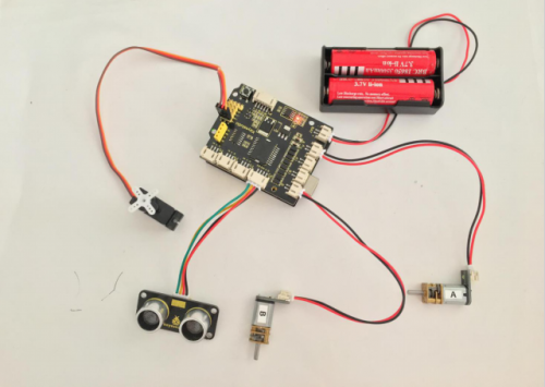
Project 4: Infrared Remote Control Robot
1) Principle and Application of Infrared Receiver
Principle of IR Remote Control:
There is no doubt that infrared remote control is commonly seen in our daily life. It's hard to imagine our world without it.
In reality, an infrared remote control can be used to control a wide range of home appliances such as television, audio, video recorders and satellite signal receivers. It is so practical. Well, in the following let’s get a better understanding of the infrared remote control.
Infrared remote control is composed of infrared transmitting and infrared receiving systems. That is, consist of an infrared remote control, an infrared receiver module and a microcontroller that can decode. You can refer to the figure below.

The 38K infrared carrier signal transmitted by an infrared remote controller is encoded by an encoding chip inside the remote controller. It is composed of a pilot code, user code, data code, and data inversion code.
The time interval between pulses is used to distinguish whether it is a signal 0 or 1. (when the ratio of high level to low level is about 1:1, considered as signal 0.) And the encoding is just well composed of signal 0 and 1.
The user code of the same button on remote controller is unchanged. Using difference data distinguish the key pressed on the remote control.
When press down a button on the remote control, it will send out an infrared carrier signal. And when infrared receiver receives that signal, its program will decode the carrier signal, and through different data codes, thus can judge which key is pressed.
The microcontroller is decoded by an received signal 0 or 1 to determine which key is pressed by the remote control.
As for an infrared receiver module, it is mainly composed of an infrared receiving head. This device integrates with reception, amplification and demodulation. Its internal IC has been demodulated, able to complete all the work from infrared reception to output TTL level signal compatible. It outputs Digital signal. Suitable for IR remote control and infrared data transmission.
The infrared receiver module has only three pins (Signal line, VCC, GND), very convenient to communicate with Arduino and other microcontrollers.
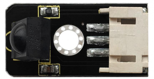
Parameters of IR Receiver:
- 1)Operating Voltage: 3.3-5V(DC)
- 2)Interface: 3PIN
- 3)Output Signal: Digital signal
- 4)Receiving Angle: 90 degrees
- 5)Frequency: 38khz
- 6)Receiving Distance: 18m
Decoding and Control of IR Remote Control:
First of all, let’s figure out the decoding. You can refer to the steps as follows:
Step 1: Connect the infrared receiver module to the P3 connector on the shield using the connector wire.
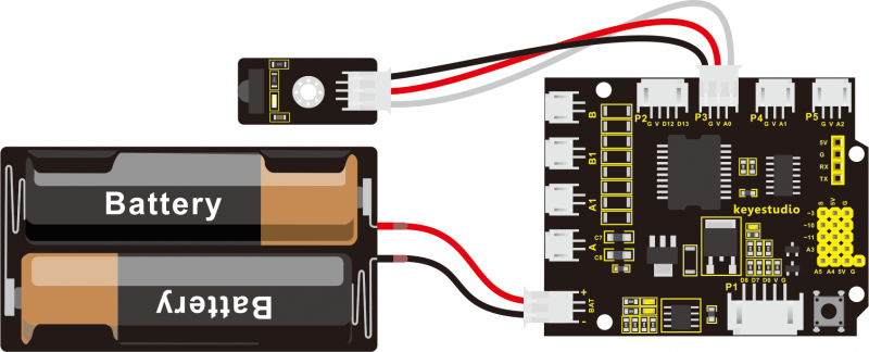
Step 2: Download the libraries of infrared remote control inside the Arduino Libraries directory.
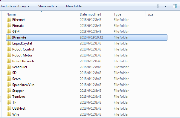
The infrared remote control libraries include transmitting and receiving functions of remote control, so that you just need to call the internal functions to control the remote control.
You can download the libraries from here: [1] ![]() IRremote.zip
IRremote.zip
Step 3: Open the Arduino IDE, upload the code to read the value of remote control.
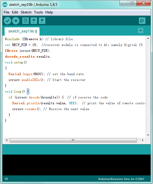
Code 12:
#include <IRremote.h> // library file
int RECV_PIN = 15;  //receiver module is connected to A1,namely Digital 15
IRrecv irrecv(RECV_PIN);
decode_results results;
void setup()
{
  Serial.begin(9600); // set the baud rate
  irrecv.enableIRIn(); // Start the receiver
}
void loop() {
  if (irrecv.decode(&results)) {  // if receive the code
    Serial.println(results.value, HEX);  // print the value of remote control
    irrecv.resume(); // Receive the next value
  }
}
Code to Note:
Before verify the above code in ArduinoIDE, do remember to add IRremote folder into \Arduino\compiler libraries directory, or it will fail to compile it.
Step 4: Upload well the above code to ARDUINO controller, then open the serial monitor and set the baud rate to 9600. Aimed at the IR receiver sensor, press down the button of remote control, you will see the corresponding encode of button is displayed on the monitor. If you press the button too long, it will easily appear a messy code like FFFFFF shown as below.
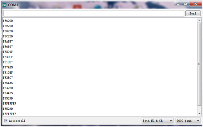
Below we have listed out each button value of keyestudio remote control. You can keep it for reference.
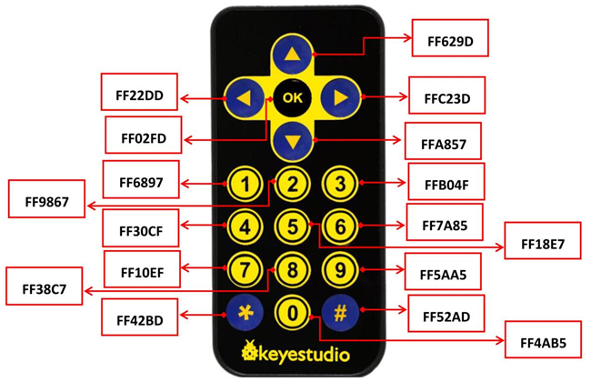
Next, let’s use the remote control to make a small experiment. Use the remote control to make 8*8 dot matrix display different images.
Hookup Guide:
Connect the IR receiver and dot matrix to the shield as the figure shown below:

Below is an example code.
Code 13:
Note: Before test the code, should add the dot matrix and IR receiver libraries to the Arduino libraries directory. If you have added them before, directly compile and upload the code below to Arduino software.
Download all the libraries folder from the link here:
https://drive.google.com/open?id=16ii-ZQTNK_Fn8KG81rhBw7JX1zQQ6nG6
#// dot matrix
#include <Wire.h>   // add the IIC libraries
#include "Adafruit_LEDBackpack.h"   // add the libraries of dot matrix
#include "Adafruit_GFX.h"
Adafruit_LEDBackpack matrix = Adafruit_LEDBackpack();   // build an object to control the dot matrix

// IR receiver
#include <IRremote.h>    // add the libraries of IR receiver
int RECV_PIN = A0;        // define the IR receiver pin as A0
IRrecv irrecv(RECV_PIN);
decode_results results;
// decoding of remote control
const long IR_front = 0x00FF629D;
const long IR_back = 0x00FFA857;
const long IR_left = 0x00FF22DD;
const long IR_right = 0x00FFC23D;
const long IR_stop = 0x00FF02FD;
const long IR_1 = 0x00FF6897;
const long IR_2 = 0x00FF9867;
const long IR_3 = 0x00FFB04F;
const long IR_4 = 0x00FF30CF;
const long IR_5 = 0x00FF18E7;
const long IR_6 = 0x00FF7A85;
const long IR_7 = 0x00FF10EF;
const long IR_8 = 0x00FF38C7;
const long IR_9 = 0x00FF5AA5;
const long IR_0 = 0x00FF52AD;

void setup()
{
  Serial.begin(9600);           // set the baud rate to 9600
  irrecv.enableIRIn();            // Start the receiver
  delay(100);           //delay 100ms

  //dot matrix
  matrix.begin(0x70);  // pass in the address
  chushi();         // the matrix display when starting up
}

void loop()
{
  if(irrecv.decode(&results))   // if receive the IR signal
  {
    int val = results.value;      // assign the received result to val
    Serial.println(val,HEX);    // print out the hexadecimal val value on the serial monitor

    switch(val)   // perform the corresponding function for the corresponding data received.
    {
      case  IR_front:  qian();  break;  // display the front arrow
      case  IR_back:  hou();    break;  // display the back arrow
      case  IR_left:  zuo();    break;  // display the left arrow
      case  IR_right:  you();   break;  //display the right arrow
      case  IR_stop:  ting();   break;   //display ×
      case  IR_1:  S();   break;         //display S
      case  IR_2:  ZZ();   break;     // display the arrow flexed to the left
      case  IR_3:  YZ();   break;    // display the arrow flexed to the right
      case  IR_4:  ZX();  break;    // display the arrow turn right in circle
      case  IR_5:  YX();  break;     // the arrow circle turn left in circle
      default : printf("error");
    }
    irrecv.resume();    // Receive the next value
  }

}

////////////////////////matrix display image////////////////////////////
// forward
void qian()
{
    matrix.displaybuffer[3] = B11111111;
    matrix.displaybuffer[4] = B11111111;
    matrix.displaybuffer[2] = B00000001;
    matrix.displaybuffer[1] = B00000010;
    matrix.displaybuffer[0] = B00000100;
    matrix.displaybuffer[5] = B00000001;
    matrix.displaybuffer[6] = B00000010;
    matrix.displaybuffer[7] = B00000100;
    matrix.writeDisplay();
}
//backward
void hou()
{
    matrix.displaybuffer[3] = B11111111;
    matrix.displaybuffer[4] = B11111111;
    matrix.displaybuffer[2] = B00100000;
    matrix.displaybuffer[1] = B00010000;
    matrix.displaybuffer[0] = B00001000;
    matrix.displaybuffer[5] = B00100000;
    matrix.displaybuffer[6] = B00010000;
    matrix.displaybuffer[7] = B00001000;
    matrix.writeDisplay();
}
//turn right
void you()
{
    for(int i=0;i<8;i++)
    {
      matrix.displaybuffer[i] = B00001100;
    }
    matrix.displaybuffer[6] = B00011110;
    matrix.displaybuffer[5] = B00101101;
    matrix.displaybuffer[4] = B11001100;
    matrix.writeDisplay();
}
//turn left
void zuo()
{
    for(int i=0;i<8;i++)
    {
      matrix.displaybuffer[i] = B00001100;
    }
    matrix.displaybuffer[1] = B00011110;
    matrix.displaybuffer[2] = B00101101;
    matrix.displaybuffer[3] = B11001100;
    matrix.writeDisplay();
}
//stop
void ting()
{
    matrix.displaybuffer[0] = B11000000;
    matrix.displaybuffer[1] = B00100001;
    matrix.displaybuffer[2] = B00010010;
    matrix.displaybuffer[3] = B00001100;
    matrix.displaybuffer[4] = B00001100;
    matrix.displaybuffer[5] = B00010010;
    matrix.displaybuffer[6] = B00100001;
    matrix.displaybuffer[7] = B11000000;
    matrix.writeDisplay();
}
//start up
void chushi()
{
    matrix.displaybuffer[0] = B00000011;
    matrix.displaybuffer[1] = B10000000;
    matrix.displaybuffer[2] = B00010011;
    matrix.displaybuffer[3] = B00100000;
    matrix.displaybuffer[4] = B00100000;
    matrix.displaybuffer[5] = B00010011;
    matrix.displaybuffer[6] = B10000000;
    matrix.displaybuffer[7] = B00000011;
    matrix.writeDisplay();
}
//S line
void S()
{
    matrix.displaybuffer[0] = B00000000;
    matrix.displaybuffer[1] = B00000000;
    matrix.displaybuffer[2] = B00110001;
    matrix.displaybuffer[3] = B11001000;
    matrix.displaybuffer[4] = B11000100;
    matrix.displaybuffer[5] = B00100011;
    matrix.displaybuffer[6] = B00000000;
    matrix.displaybuffer[7] = B00000000;
    matrix.writeDisplay();
}
// turn around the wheel on the left
void ZZ()
{
    matrix.displaybuffer[0] = B00000000;
    matrix.displaybuffer[1] = B10000011;
    matrix.displaybuffer[2] = B11000001;
    matrix.displaybuffer[3] = B10100010;
    matrix.displaybuffer[4] = B00010100;
    matrix.displaybuffer[5] = B00001000;
    matrix.displaybuffer[6] = B00000000;
    matrix.displaybuffer[7] = B00000000;
    matrix.writeDisplay();
}
// turn around the wheel on the right
void YZ()
{
    matrix.displaybuffer[0] = B00000000;
    matrix.displaybuffer[1] = B00000000;
    matrix.displaybuffer[2] = B00001000;
    matrix.displaybuffer[3] = B00010100;
    matrix.displaybuffer[4] = B10100010;
    matrix.displaybuffer[5] = B11000001;
    matrix.displaybuffer[6] = B10000011;
    matrix.displaybuffer[7] = B00000000;
    matrix.writeDisplay();
}
//  turn left in circle
void ZX()
{
    matrix.displaybuffer[0] = B00000000;
    matrix.displaybuffer[1] = B00011100;
    matrix.displaybuffer[2] = B00100010;
    matrix.displaybuffer[3] = B01000001;
    matrix.displaybuffer[4] = B00000001;
    matrix.displaybuffer[5] = B00111001;
    matrix.displaybuffer[6] = B00110010;
    matrix.displaybuffer[7] = B00101100;
    matrix.writeDisplay();
}
//  turn right in circle
void YX()
{
    matrix.displaybuffer[0] = B00001100;
    matrix.displaybuffer[1] = B00110010;
    matrix.displaybuffer[2] = B00111001;
    matrix.displaybuffer[3] = B00000001;
    matrix.displaybuffer[4] = B00000001;
    matrix.displaybuffer[5] = B00100010;
    matrix.displaybuffer[6] = B00011100;
    matrix.displaybuffer[7] = B00000000;
    matrix.writeDisplay();
}
What you will see?
Upload the above code to the board, and turn on the POWER button on the shield. Aligned with the IR receiver, use remote control to control the turtle robot run, showing the running states on the dot matrix display.
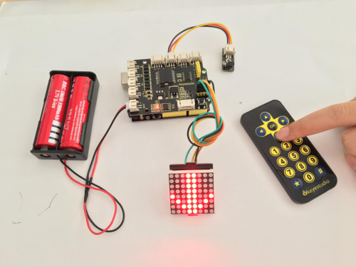
2) Infrared Control Turtle Robot
Overview:
In the previous section, we have introduced how to use an IR remote control to control a 8*8 dot matrix. So think that how to control the smart robot with an IR remote control.
It is very simple. Use ARDUINO board to analyze and judge the collected infrared signal so as to drive the motor forward,backward and turn.
You can apply the decoding value of remote control mentioned before to the code that used to control the robot with IR remote control.
It also adds a 8*8 dot matrix to display the running state of turtle robot.
Wiring Diagram:
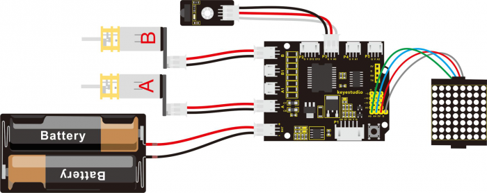
Next let’s look back to the decoding value of IR remote control.

You can get the details:
- Forward button: 0x00FF629D
- Backward button: 0x00FFA857
- Stop button: 0x00FF02FD
- Left button: 0x00FF22DD
- Right Button: 0x00FFC23D
You can apply those data to the code of infrared controlled robot.
Code 14:
Note: Before test the code, should add all the libraries needed to the Arduino libraries directory. If you have added them before, directly compile and upload the code below to Arduino software.
Download all the libraries folder from the link here:
https://drive.google.com/open?id=16ii-ZQTNK_Fn8KG81rhBw7JX1zQQ6nG6
//DOT MATRIX
#include <Wire.h>   // add IIC libraries
#include "Adafruit_LEDBackpack.h"   // add the libraries of matrix display
#include "Adafruit_GFX.h"
Adafruit_LEDBackpack matrix = Adafruit_LEDBackpack();   // build an object to control a dot matrix

// IR receiver
#include <IRremote.h>    // add the libraries of IR receiver
int RECV_PIN = A0;        // define the ir receiver pin as A0
IRrecv irrecv(RECV_PIN);
decode_results results;
// decoding value of ir receiver
const long IR_front = 0x00FF629D;
const long IR_back = 0x00FFA857;
const long IR_left = 0x00FF22DD;
const long IR_right = 0x00FFC23D;
const long IR_stop = 0x00FF02FD;
const long IR_1 = 0x00FF6897;
const long IR_2 = 0x00FF9867;
const long IR_3 = 0x00FFB04F;
const long IR_4 = 0x00FF30CF;
const long IR_5 = 0x00FF18E7;
const long IR_6 = 0x00FF7A85;
const long IR_7 = 0x00FF10EF;
const long IR_8 = 0x00FF38C7;
const long IR_9 = 0x00FF5AA5;
const long IR_0 = 0x00FF52AD;

// control two motors
#define INT_A 2    // control the left motor direction pin D2
#define INT_B 4    // control the right motor direction pin D4
#define left_A 9    // define the left motor speed control pin as D9
#define right_B 5   // define the right motor speed control pin as D5
int i=0;
long val;       // define a variable to receive the signal sent by IR transmitter


void setup()
{
  Serial.begin(9600);           // set the serial baud rate to 9600
  irrecv.enableIRIn();            // Start the receiver
  delay(100);           // delay 100ms
  pinMode(INT_A,OUTPUT);           // set the motor control pin as OUTPUT
  pinMode(INT_B,OUTPUT);
  pinMode(left_A,OUTPUT);
  pinMode(right_B,OUTPUT);

  // DOT MATRIX
  matrix.begin(0x70);  // pass in the address
  chushi();         //initial matrix display
}

void loop()
{
  i = 1;
  if(irrecv.decode(&results))   // if receive the infrared signal
  {
    val = results.value;      // assign the result value to val
    Serial.println(val,HEX);    // print out hexadecimal val value on the serial monitor

    switch(val)   // perform the corresponding function for the received data
    {
      case  IR_front:  front(),qian();  break;  // if receive the(IR_front = 0x00FF629D),perform the front function(front())and matrix display function(qian())
      case  IR_back:  back(),hou();    break;  // backward
      case  IR_left:  left(),zuo();    break;  // turn left
      case  IR_right:  right(),you();   break;  // turn right
      case  IR_stop:  Stop(),ting();   break;   // stop
      case  IR_1:  front_s();   break;          // walk in S line
      case  IR_2:  left_l(),ZZ();   break;     // turn around the wheel on the left
      case  IR_3:  right_l(),YZ();   break;    // turn around the wheel on the right
      case  IR_4:  right_r(),ZX();  break;    // turn a circle to the right
      case  IR_5:  left_r(),YX();  break;     // turn a circle to the left

      default : printf("error");
    }
    irrecv.resume();    // Receive the next value
  }

}

// go forward
void front()
{
  digitalWrite(INT_A,LOW);    // control the left motor turn forward
  digitalWrite(INT_B,LOW);   // control the right motor turn forward
  analogWrite(left_A,200);   // set the two motors’ speed(PWM=200)
  analogWrite(right_B,200);
}
// backward
void back()
{
  digitalWrite(INT_A,HIGH);   // control the left motor turn backward
  digitalWrite(INT_B,HIGH);    // control the right motor turn backward
  analogWrite(left_A,200);   // set the two motors’ speed (PWM=200)
  analogWrite(right_B,200);
}
// turn left
void left()
{
  digitalWrite(INT_A,HIGH);    // control the left motor turn backward
  digitalWrite(INT_B,LOW);    // control the right motor turn forward
  analogWrite(left_A,100);    // set the two motors’ speed(PWM为100)
  analogWrite(right_B,100);
}
// turn right
void right()
{
  digitalWrite(INT_A,LOW);     // control the left motor turn forward
  digitalWrite(INT_B,HIGH);     // control the right motor turn backward
  analogWrite(left_A,100);    // two motors’ speed(PWM为100)
  analogWrite(right_B,100);
}
// stop
void Stop()
{
  digitalWrite(INT_A,LOW);
  digitalWrite(INT_B,LOW);
  analogWrite(left_A,0);    // both PWM are 0
  analogWrite(right_B,0);
}
//walk in S line
void front_s()
{
  S();
  while(i>0)
  {
    digitalWrite(INT_A,LOW);   // control the left motor turn forward
    digitalWrite(INT_B,LOW);   // control the right motor turn forward
    analogWrite(left_A,50);   // left motor PWM=100
    analogWrite(right_B,255);  // right motor PWM=255  (walk in S line to the left)
    delay(300);      // delay 1S
    analogWrite(left_A,255);   // left motor PWM=255
    analogWrite(right_B,50);  // right motor PWM=100  (walk in S line to the right)
    delay(300);      // delay 1S
    if(irrecv.decode(&results))   // if receive the infrared signal
    {
      irrecv.resume();    // Receive the next value
      val=results.value;    // assign the received data to val
      if(val==IR_stop)   // if receive the stop command
      {
        Stop();       // stop
        break;        // exit the current function
      }
    }
  }
}
//turn around the wheel on the left
void left_l()
{
    digitalWrite(INT_A,HIGH);   // control the left motor turn backward
    digitalWrite(INT_B,LOW);   // control the right motor turn forward
    analogWrite(left_A,0);     //left PWM=0,left wheel stops
    analogWrite(right_B,200);    //right PWM=200,right wheel goes front
}
// turn around the wheel on the right
void right_l()
{
    digitalWrite(INT_A,HIGH);   // control the left motor turn backward
    digitalWrite(INT_B,LOW);   // control the right motor turn forward
    analogWrite(left_A,200);   //left PWM=200, left wheel goes forward
    analogWrite(right_B,0);    //right PWM=0,right wheel stops
}
// turn a circle to the right
void right_r()
{
    digitalWrite(INT_A,LOW);    // control the left motor turn forward
    digitalWrite(INT_B,LOW);   // control the right motor turn forward
    analogWrite(left_A,100);   // left motor PWM=100
    analogWrite(right_B,200);   // right motor PWM=200 (car turns around to the left)
}

// turn around to the left
void left_r()
{
    digitalWrite(INT_A,LOW);    // control the left motor turn forward
    digitalWrite(INT_B,LOW);   // control the right motor turn forward
    analogWrite(left_A,200);   // left motor PWM=100
    analogWrite(right_B,100);   // right motor PWM=200 ( car turns around to the left)
}

////////////////////////matrix display image////////////////////////////
// front image
void qian()
{
    matrix.displaybuffer[3] = B11111111;
    matrix.displaybuffer[4] = B11111111;
    matrix.displaybuffer[2] = B00000001;
    matrix.displaybuffer[1] = B00000010;
    matrix.displaybuffer[0] = B00000100;
    matrix.displaybuffer[5] = B00000001;
    matrix.displaybuffer[6] = B00000010;
    matrix.displaybuffer[7] = B00000100;
    matrix.writeDisplay();
}
// back image
void hou()
{
    matrix.displaybuffer[3] = B11111111;
    matrix.displaybuffer[4] = B11111111;
    matrix.displaybuffer[2] = B00100000;
    matrix.displaybuffer[1] = B00010000;
    matrix.displaybuffer[0] = B00001000;
    matrix.displaybuffer[5] = B00100000;
    matrix.displaybuffer[6] = B00010000;
    matrix.displaybuffer[7] = B00001000;
    matrix.writeDisplay();
}
//right image
void you()
{
    for(int i=0;i<8;i++)
    {
      matrix.displaybuffer[i] = B00001100;
    }
    matrix.displaybuffer[6] = B00011110;
    matrix.displaybuffer[5] = B00101101;
    matrix.displaybuffer[4] = B11001100;
    matrix.writeDisplay();
}
// left image
void zuo()
{
    for(int i=0;i<8;i++)
    {
      matrix.displaybuffer[i] = B00001100;
    }
    matrix.displaybuffer[1] = B00011110;
    matrix.displaybuffer[2] = B00101101;
    matrix.displaybuffer[3] = B11001100;
    matrix.writeDisplay();
}
// stop image
void ting()
{
    matrix.displaybuffer[0] = B11000000;
    matrix.displaybuffer[1] = B00100001;
    matrix.displaybuffer[2] = B00010010;
    matrix.displaybuffer[3] = B00001100;
    matrix.displaybuffer[4] = B00001100;
    matrix.displaybuffer[5] = B00010010;
    matrix.displaybuffer[6] = B00100001;
    matrix.displaybuffer[7] = B11000000;
    matrix.writeDisplay();
}
// initial image
void chushi()
{
    matrix.displaybuffer[0] = B00000011;
    matrix.displaybuffer[1] = B10000000;
    matrix.displaybuffer[2] = B00010011;
    matrix.displaybuffer[3] = B00100000;
    matrix.displaybuffer[4] = B00100000;
    matrix.displaybuffer[5] = B00010011;
    matrix.displaybuffer[6] = B10000000;
    matrix.displaybuffer[7] = B00000011;
    matrix.writeDisplay();
}
//S line
void S()
{
    matrix.displaybuffer[0] = B00000000;
    matrix.displaybuffer[1] = B00000000;
    matrix.displaybuffer[2] = B00110001;
    matrix.displaybuffer[3] = B11001000;
    matrix.displaybuffer[4] = B11000100;
    matrix.displaybuffer[5] = B00100011;
    matrix.displaybuffer[6] = B00000000;
    matrix.displaybuffer[7] = B00000000;
    matrix.writeDisplay();
}
// turn around the wheel on the left
void ZZ()
{
    matrix.displaybuffer[0] = B00000000;
    matrix.displaybuffer[1] = B10000011;
    matrix.displaybuffer[2] = B11000001;
    matrix.displaybuffer[3] = B10100010;
    matrix.displaybuffer[4] = B00010100;
    matrix.displaybuffer[5] = B00001000;
    matrix.displaybuffer[6] = B00000000;
    matrix.displaybuffer[7] = B00000000;
    matrix.writeDisplay();
}
// turn around the wheel on the right
void YZ()
{
    matrix.displaybuffer[0] = B00000000;
    matrix.displaybuffer[1] = B00000000;
    matrix.displaybuffer[2] = B00001000;
    matrix.displaybuffer[3] = B00010100;
    matrix.displaybuffer[4] = B10100010;
    matrix.displaybuffer[5] = B11000001;
    matrix.displaybuffer[6] = B10000011;
    matrix.displaybuffer[7] = B00000000;
    matrix.writeDisplay();
}
// turn around to the left
void ZX()
{
    matrix.displaybuffer[0] = B00000000;
    matrix.displaybuffer[1] = B00011100;
    matrix.displaybuffer[2] = B00100010;
    matrix.displaybuffer[3] = B01000001;
    matrix.displaybuffer[4] = B00000001;
    matrix.displaybuffer[5] = B00111001;
    matrix.displaybuffer[6] = B00110010;
    matrix.displaybuffer[7] = B00101100;
    matrix.writeDisplay();
}
// turn around to the right
void YX()
{
    matrix.displaybuffer[0] = B00001100;
    matrix.displaybuffer[1] = B00110010;
    matrix.displaybuffer[2] = B00111001;
    matrix.displaybuffer[3] = B00000001;
    matrix.displaybuffer[4] = B00000001;
    matrix.displaybuffer[5] = B00100010;
    matrix.displaybuffer[6] = B00011100;
    matrix.displaybuffer[7] = B00000000;
    matrix.writeDisplay();
}
What you will see?
Upload the above code to the board, and turn on the POWER button on the shield. Aligned with the IR receiver, use remote control to control the turtle robot run, showing the running states on the dot matrix display.
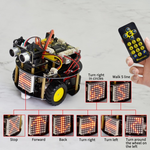
Project 5: Bluetooth Controlled Robot
1) Principle and Application of Bluetooth Remote Control
Bluetooth, as the name implies, blue teeth, and he is not used to bite people, but a wireless data transmission method. Bluetooth technology is a wireless standard technology that enables short-range data exchange among fixed devices, mobile devices, and personal area networks of buildings (UHF radio waves in the ISM band of 2.4 to 2.485 GHz).
There are two kinds of commonly used Bluetooth module on the market, HC-05 and HC-06 models. The difference between them is that the HC-05 is a master-slave one.
It can not only make small reports to its own “master”, but also can receive the command given to it. The HC-06 can only work in slave mode, which can only accept the superior command. For instance, in many cases you may want to be an overbearing man, letting the subordinates obey the order without any nonsense. So in such situation, it is enough to use the HC-06 module shown as below.
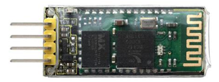
Specification Parameters:
- 1) Bluetooth Protocol: Bluetooth 2.1+ EDR Standard
- 2) USB Protocol: USB v1.1/2.0
- 3) Operating Frequency: 2.4GHz ISM Frequency Band
- 4) Modulation Mode: Gauss Frequency Shift Keying
- 5) Transmit Power: ≤ 4dBm, Second Stage
- 6) Sensitivity: ≤-84dBm at 0.1% Bit Error Rate
- 7) Transmission Speed: 2.1Mbps(Max)/160 kbps(Asynchronous);1Mbps/1Mbps(Synchronous)
- 8) Safety Feature: Authentication and Encryption
- 9) Supported Configuration: Bluetooth Serial Port (major and minor)
- 10) Supply Voltage: DC 5V
- 11) Operating Temperature: -20 to 55℃
Wiring Diagram:
Next, we are going to do a small experiment. When Bluetooth module receives a signal sent by phone, finally control an LED on and off.

Test Code 15:
int val;
int led=11;
void setup()
{
Serial.begin(9600);
pinMode(11,OUTPUT);
}
 void loop()
{ val=Serial.read();
if(val=='U')
 {
 digitalWrite(11, HIGH);   // turn the LED on (HIGH is the voltage level)
 }
if(val=='D')
 {
 digitalWrite(11, LOW);    // turn the LED off by making the voltage LOW
 }
 }
After wiring, upload the above code to the board, and connect the Bluetooth module. Pay more attention to the connecting direction. Plug it correctly and you should see an LED on the module flash.
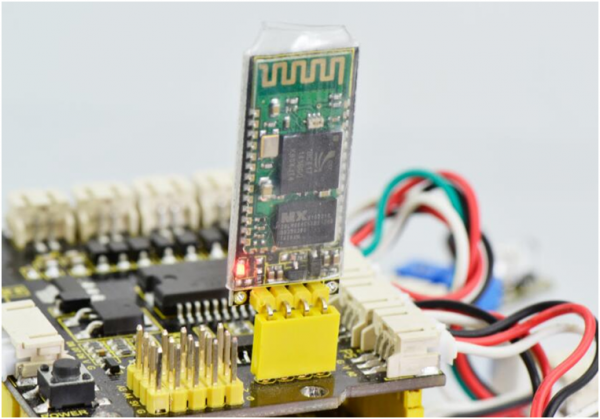
Pay special attention to:
You must first upload the code to the board and then plug in the Bluetooth module, otherwise the program fails to compile. Because the data transmits of Bluetooth module will occupy the microcontroller’s TX and RX pins that are also used for the code upload of microcontroller, it exists a conflict.
After uploading the code, you have to do another thing, that is, install an application of Bluetooth serial assistant on the phone.
You can click the link below to download the Bluetooth serial assistant:
https://drive.google.com/open?id=1D16V4HZ5H6k7p1-NMCqb0JRy_dl5tvuC
The Bluetooth we used here is Bluetooth 2.0. Currently, it only supports the Android devices. Do not support Apple devices. Please pay attention to this when using it.
After the serial assistant is installed, must first connect the device, open the mobile Bluetooth, search for a Bluetooth device. If find a Bluetooth device named HC-06, pair and enter 1234, finally you should see the paired device shown as below.
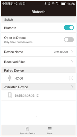
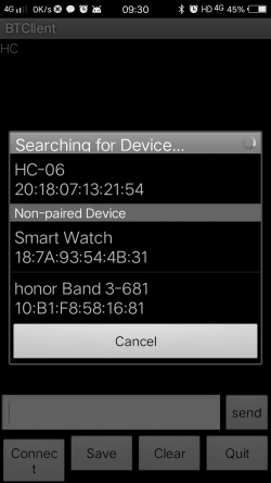
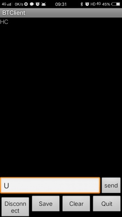
Then open the Bluetooth serial communication APP, namely BT Client, and connect well the Bluetooth just paired.
Done connecting, an LED on the Bluetooth module is always on. If enter the letter U in the Bluetooth APP, the LED connected on the pin 11is on; if enter the letter D, the LED is off.
2) Bluetooth Controlled Turtle Robot
In the previous section, you have learned the principles of Bluetooth and how to use Bluetooth to control a small light. Okay, based on that, could we use Bluetooth to send a command to control the robot run?
Absolutely yeah. In the previous section, we can use a mobile APP to send a character. Use a Bluetooth module to receive the Bluetooth signal from the mobile phone, and feed it back to the main control board. Then main control board will analyze and judge the collected signals. If correct, it will control the robot run.
Here we don't need a Bluetooth serial assistant as mentioned above. Just use an Android APP developed by our keyestudio team to control the robot.
You can click the link to download the APP:
https://drive.google.com/open?id=1g-bwP1SyJVfQseywRORQ6rOJOVd3JU5i
The interface of this APP is very simple, as shown below.
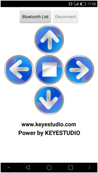
Connected the Bluetooth, let’s make use of a little program that can read the serial data, to check what character the five buttons send. Then apply them to the example code for Bluetooth robot in the following projects.
Test Code 16:
char val; // define the variable val
void setup()
{
Serial.begin(9600);// set the baud rate as 9600, the same as software setting. When connecting the particular device like Bluetooth, it should be consistent with the baud rate of other devices.
}
void loop()
{
val=Serial.read();//read the data received from serial port, and assign it to val
Serial.println(val);// print val data
delay(300);//delay 0.3S
}
Through the above program, we can get that five buttons are Upward (“U”), Downward (“D”), Left (“L”), Right (“R”), and Stop (“S”). The principle is very simple.
When Bluetooth module receives these characters sent by the mobile phone, and then it will send them to ARDUINO. ARDUINO will control the rotation direction of motor according to the preset value in the code.
When receive the information "U", smart robot will move forward. When receive "D", it goes backward. If receive "L", turn left. If receive "R", turn right. The smart car will stop when receive the "S".
Hookup Guide:
Note: Bluetooth module is directly plugged into the shield.
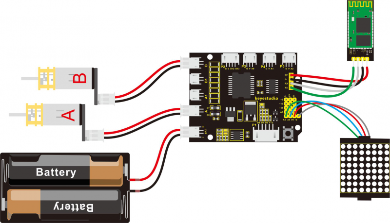
After wiring, you can get the project code as follows:
Test Code 17:
Note: Before test the code, should add the libraries needed to the Arduino libraries directory. If you have added them before, directly compile and upload the code below to Arduino software.
Download all the libraries folder from the link here:
https://drive.google.com/open?id=16ii-ZQTNK_Fn8KG81rhBw7JX1zQQ6nG6
Pay special attention: should first upload the code successfully, then connect the Bluetooth module. Otherwise, fail to upload the code.
#include <Wire.h>
#include "Adafruit_LEDBackpack.h"
#include "Adafruit_GFX.h"
Adafruit_LEDBackpack matrix = Adafruit_LEDBackpack();

#define INT_A 2    //define the left motor control pin as D2
#define INT_B 4    // define the right motor control pin as D4
#define left_A 9     // define the left motor speed pin as D9
#define right_B 5    // define the right motor speed pin as D5

void setup()
{
  Serial.begin(9600);     // set the baud rate of monitor to 9600
  delay(100);     //delay 100ms
  pinMode(INT_A,OUTPUT);    // set the motor control pin as OUTPUT
  pinMode(INT_B,OUTPUT);
  pinMode(left_A,OUTPUT);
  pinMode(right_B,OUTPUT);

  // DOT matrix
  matrix.begin(0x70);  // pass in the address
  chushi();       // initial matrix image
}

void loop()
{
  int val;    //define the variable, used to receive the data from Bluetooth
  if(Serial.available())     // if receive the data
  {
    val = Serial.read();       // assign the data read to val
  }
  switch(val)    // perform the corresponding function for data received
  {
    case 'U':  front(),qian();  break;   //if val equals U,then perform the front function(front())and image function(qian()),break statement means that exist the current function if receive other data
    case 'D':  back(),hou();   break;    //backward
    case 'L':  left(),zuo();   break;    // turn left
    case 'R':  right(),you();  break;    // turn right
    case 'S':  Stop(),ting();   break;   // stop
    default :Serial.print("error");
  }

}

// go front
void front()
{
  digitalWrite(INT_A,LOW);    // control the left motor rotate forward
  digitalWrite(INT_B,LOW);   // control the right motor rotate forward
  analogWrite(left_A,200);   // set the two motors’ speed(PWM=200)
  analogWrite(right_B,200);
}
// backward
void back()
{
  digitalWrite(INT_A,HIGH);   // control the left motor rotate backward
  digitalWrite(INT_B,HIGH);    // control the right motor rotate backward
  analogWrite(left_A,200);
  analogWrite(right_B,200);
}
// turn left
void left()
{
  digitalWrite(INT_A,HIGH);    // control the left motor rotate backward
  digitalWrite(INT_B,LOW);    // control the right motor rotate forward
  analogWrite(left_A,100);    // two motors’ speed(PWM为100)
  analogWrite(right_B,100);
}
// turn right
void right()
{
  digitalWrite(INT_A,LOW);     // control the left motor rotate forward
  digitalWrite(INT_B,HIGH);     // control the right motor rotate backward
  analogWrite(left_A,100);
  analogWrite(right_B,100);
}
// stop
void Stop()
{
  digitalWrite(INT_A,LOW);
  digitalWrite(INT_B,LOW);
  analogWrite(left_A,0);    //both PWM are 0
  analogWrite(right_B,0);
}

/////////////////////dot matrix/////////////////////////
// front image
void qian()
{
    matrix.displaybuffer[3] = B11111111;
    matrix.displaybuffer[4] = B11111111;
    matrix.displaybuffer[2] = B00000001;
    matrix.displaybuffer[1] = B00000010;
    matrix.displaybuffer[0] = B00000100;
    matrix.displaybuffer[5] = B00000001;
    matrix.displaybuffer[6] = B00000010;
    matrix.displaybuffer[7] = B00000100;
    matrix.writeDisplay();
}
// backward image
void hou()
{
    matrix.displaybuffer[3] = B11111111;
    matrix.displaybuffer[4] = B11111111;
    matrix.displaybuffer[2] = B00100000;
    matrix.displaybuffer[1] = B00010000;
    matrix.displaybuffer[0] = B00001000;
    matrix.displaybuffer[5] = B00100000;
    matrix.displaybuffer[6] = B00010000;
    matrix.displaybuffer[7] = B00001000;
    matrix.writeDisplay();
}
// turn right image
void you()
{
    for(int i=0;i<8;i++)
    {
      matrix.displaybuffer[i] = B00001100;
    }
    matrix.displaybuffer[6] = B00011110;
    matrix.displaybuffer[5] = B00101101;
    matrix.displaybuffer[4] = B11001100;
    matrix.writeDisplay();
}
// turn left image
void zuo()
{
    for(int i=0;i<8;i++)
    {
      matrix.displaybuffer[i] = B00001100;
    }
    matrix.displaybuffer[1] = B00011110;
    matrix.displaybuffer[2] = B00101101;
    matrix.displaybuffer[3] = B11001100;
    matrix.writeDisplay();
}
// stop image
void ting()
{
    matrix.displaybuffer[0] = B11000000;
    matrix.displaybuffer[1] = B00100001;
    matrix.displaybuffer[2] = B00010010;
    matrix.displaybuffer[3] = B00001100;
    matrix.displaybuffer[4] = B00001100;
    matrix.displaybuffer[5] = B00010010;
    matrix.displaybuffer[6] = B00100001;
    matrix.displaybuffer[7] = B11000000;
    matrix.writeDisplay();
}
// initial image
void chushi()
{
    matrix.displaybuffer[0] = B00000011;
    matrix.displaybuffer[1] = B10000000;
    matrix.displaybuffer[2] = B00010011;
    matrix.displaybuffer[3] = B00100000;
    matrix.displaybuffer[4] = B00100000;
    matrix.displaybuffer[5] = B00010011;
    matrix.displaybuffer[6] = B10000000;
    matrix.displaybuffer[7] = B00000011;
    matrix.writeDisplay();
}
Example Result:
Done uploading the above code to control board, turn on the POWER button on the shield, then open APP, connect to Bluetooth, you should see the LED on the Bluetooth module is normally on.
Press down any buttons on APP, you can control the smart robot to run freely, showing the state image on the dot matrix display.
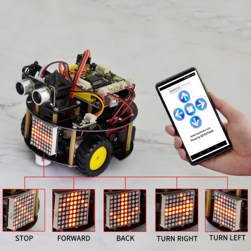
Project 6: 4 in 1 Complete Robot
Overview:
In the above projects, we have introduced four functions for the turtle robot, that is, line following, avoiding obstacles, IR control and Bluetooth remote control.
Now, let’s combine those functions together to make a complete robot. You can use the IR module to switch the functions.
Function switching methods:
Powered on and aligned with the IR receiver, press the number 1 on the IR remote control, the turtle robot will enter the line tracking function. Then press the key OK, it will exist the tracking function.
- If press the number 2, enter the obstacle avoidance function, and press OK to end that function.
- If press the number 3, enter the S line forward, and press OK to end the function.
- If press the number 4, the robot will turn around the wheel on the left, and press OK to end the function.
- If press the number 5, the robot will turn a circle to the left, and press OK to end the function.
- If press the number 6, the robot will turn a circle to the right, and press OK to end the function.
When exist the function modes, be able to control the car through infrared control or Phone-Bluetooth control.
Test Code 18:
Note: Before test the code, should add all the libraries needed to the Arduino libraries directory. If you have added them before, directly compile and upload the code below to Arduino software.
Download all the libraries folder from the link here:
https://drive.google.com/open?id=16ii-ZQTNK_Fn8KG81rhBw7JX1zQQ6nG6
// dot matrix
#include <Wire.h>   // add IIC file
#include "Adafruit_LEDBackpack.h"
#include "Adafruit_GFX.h"
Adafruit_LEDBackpack matrix = Adafruit_LEDBackpack();   // build an object to control the dot matrix

// IR receiver
#include <IRremote.h>    // add the IR receiver libraries
int RECV_PIN = A0;        // define the IR receiver pin as A0
IRrecv irrecv(RECV_PIN);
decode_results results;
// decoding of IR remote control
const long IR_front = 0x00FF629D;
const long IR_back = 0x00FFA857;
const long IR_left = 0x00FF22DD;
const long IR_right = 0x00FFC23D;
const long IR_stop = 0x00FF02FD;
const long IR_1 = 0x00FF6897;
const long IR_2 = 0x00FF9867;
const long IR_3 = 0x00FFB04F;
const long IR_4 = 0x00FF30CF;
const long IR_5 = 0x00FF18E7;
const long IR_6 = 0x00FF7A85;
const long IR_7 = 0x00FF10EF;
const long IR_8 = 0x00FF38C7;
const long IR_9 = 0x00FF5AA5;
const long IR_0 = 0x00FF52AD;

// line following
const int S1 = 8;  // the S1 tracking sensor control pin to D8
const int S2 = 7;  // the S2 tracking sensor control pin to D7
const int S3 = 6;  // the S3 tracking sensor control pin to D6
int s1,s2,s3;   // define 3 variables,separately used to receive the digital value read by 3 tracking sensors(0 or 1)

// avoiding obstacles
const int servopin=3;// define the digital 3 to connect to servo signal line
//int myangle;// define the angle
//int pulsewidth;// define the pulsewidth
#include <SR04.h>    // add the ultrasonic libraries
#define TRIG_PIN 12   // define the pin ting of ultrasonic as D12
#define ECHO_PIN 13   //  define the pin echo of ultrasonic as D13
SR04 sr04 = SR04(ECHO_PIN,TRIG_PIN);    // build an object to control the ultrasonic
long a,a1,a2;      // used to receive the distance measured by ultrasonic
// end the obstacle avoidance

// control two motors
#define INT_A 2    // control the left motor direction pin as D2
#define INT_B 4    // control the right motor direction pin as D4
#define left_A 9    // control the left motor speed pin as D9
#define right_B 5   //control the right motor direction pin as D5


long val;       // define a variable to receive the signal from IR transmitter
int i=0;

void setup()
{
  Serial.begin(9600);           // set the baud rate of serial monitor to 9600
  irrecv.enableIRIn();            // Start the receiver
  delay(100);           // delay 100ms
  pinMode(INT_A,OUTPUT);           // set the motor control pin as OUTPUT
  pinMode(INT_B,OUTPUT);
  pinMode(left_A,OUTPUT);
  pinMode(right_B,OUTPUT);

  // DOT matrix
  matrix.begin(0x70);  // pass in the address
  chushi();         // initial matrix display

  pinMode(servopin,OUTPUT);// set the servo pin as OUTPUT
   // make the ultrasonic turn front
        for(int i=0;i<=100;i++) // give enough time to servo to rotate to specific angle
        {
        digitalWrite(servopin,HIGH);// set the servo pin to HIGH
        delayMicroseconds(1200);// delay the microseconds of pulsewidth
        digitalWrite(servopin,LOW);// set the servo pin to LOW
        delayMicroseconds(18800);// delay the microseconds of pulsewidth
        }
}

void loop()
{
  i=1;
  Bluetooth();     // Bluetooth control
  if(irrecv.decode(&results))   // if receive the infrared signal
  {
    val = results.value;      // assign the result to val
    Serial.println(val,HEX);    // print out the hexadecimal val value on the monitor

    irrecv.resume();    // Receive the next value
 }
 switch(val)   // perform the corresponding function for the data received
    {
      case  IR_front:  front(),qian();  break;   // go front and display the front image //if val equals to IR_front(IR_front=0x00FF629D),perform front() and qian() these two subfunctions,break statement is used to exist the current function
      case  IR_back:  back(),hou();    break;    // backward and show the back image
      case  IR_left:  left(),zuo();    break;    // turn left and show the left image
      case  IR_right:  right(),you();   break;   // turn right and show the right image
      case  IR_stop:  Stop(),ting();   break;    // stop and show the stop image
      case  IR_1:  xunji(),val=0;   break;       // enter the tracking function( press stop to end the function)
      case  IR_2:  bizhang(),val=0;   break;     // enter the obstacle avoiding function( press stop to end the function)
      case  IR_3:  left_l(),ZZ();  break;        // turn around the wheel on the left
      case  IR_4:  right_run(),YX();   break;    // turn around to the right
      case  IR_5:  front_s();  break;        // go front in S line and display S image
      case  IR_6:  left_run(),ZX();   break;    //  turn around to the left
      default : printf("error");
    }

}

// go front
void front()
{
    digitalWrite(INT_A,LOW);    // control the left motor turn forward
    digitalWrite(INT_B,LOW);   // control the right motor turn forward
    analogWrite(left_A,200);   // set the two motors’ speed (PWM=200)
    analogWrite(right_B,200);
}
// go backward
void back()
{
  digitalWrite(INT_A,HIGH);   //  control the left motor turn backward
  digitalWrite(INT_B,HIGH);    // control the right motor turn backward
  analogWrite(left_A,200);   // set the two motors’ speed(PWM=200)
  analogWrite(right_B,200);
}
// turn left
void left()
{
  digitalWrite(INT_A,HIGH);    // control the left motor turn backward
  digitalWrite(INT_B,LOW);    // control the right motor turn forward
  analogWrite(left_A,150);    //  set the two motors’ speed(PWM为150)
  analogWrite(right_B,150);
}
//turn right
void right()
{
  digitalWrite(INT_A,LOW);     //  control the left motor turn forward
  digitalWrite(INT_B,HIGH);     //  control the right motor turn backward
  analogWrite(left_A,150);    //  set the two motors’ speed(PWM为150)
  analogWrite(right_B,150);
}
// stop
void Stop()
{
  digitalWrite(INT_A,LOW);
  digitalWrite(INT_B,LOW);
  analogWrite(left_A,0);    // both PWM are 0
  analogWrite(right_B,0);
}
// turn around the wheel on the left
void left_l()
{
    digitalWrite(INT_A,HIGH);   // control the left motor turn backward
    digitalWrite(INT_B,LOW);   // control the right motor turn forward
    analogWrite(left_A,0);     //left PWM=0,means that the left wheel stops
    analogWrite(right_B,255);    //right PWM=255,right wheel goes forward
}
// turn around to the right
void right_run()
{
    digitalWrite(INT_A,LOW);    //control the left motor turn forward
    digitalWrite(INT_B,LOW);   //  control the right motor turn forward
    analogWrite(left_A,255);   // left motor PWM=255
    analogWrite(right_B,100);   // right motor PWM=100
}
// turn around to the left
void left_run()
{
    digitalWrite(INT_A,LOW);    // control the left motor turn forward
    digitalWrite(INT_B,LOW);   // control the right motor turn forward
    analogWrite(left_A,200);   // left motor PWM=100
    analogWrite(right_B,100);   // right motor PWM=200 (turn a circle to the left)
}

// go front in S line
void front_s()
{
    S();
  while(i>0)
  {
    digitalWrite(INT_A,LOW);   // control the left motor turn forward
    digitalWrite(INT_B,LOW);   // control the right motor turn forward
    analogWrite(left_A,50);   // left motor PWM=100
    analogWrite(right_B,255);  // right motor PWM=255  ( walk in curved line to the left)
    delay(300);      //delay 1 second
    analogWrite(left_A,255);   //left motor PWM=255
    analogWrite(right_B,50);  //right motor PWM=100  ( walk in curved line to the right )
    delay(300);      //delay 1S
    if(irrecv.decode(&results))   // if receive the infrared signal
    {
      irrecv.resume();    // Receive the next value
      val=results.value;    // assign the received data to val
      if(val==IR_stop)   // if receive the stop command
      {
        Stop();       // stop
        break;        // end the current function
      }
    }
  }
}
////////////////////////matrix display image////////////////////////////
// front image
void qian()
{
    matrix.displaybuffer[3] = B11111111;
    matrix.displaybuffer[4] = B11111111;
    matrix.displaybuffer[2] = B00000001;
    matrix.displaybuffer[1] = B00000010;
    matrix.displaybuffer[0] = B00000100;
    matrix.displaybuffer[5] = B00000001;
    matrix.displaybuffer[6] = B00000010;
    matrix.displaybuffer[7] = B00000100;
    matrix.writeDisplay();
}
// back image
void hou()
{
    matrix.displaybuffer[3] = B11111111;
    matrix.displaybuffer[4] = B11111111;
    matrix.displaybuffer[2] = B00100000;
    matrix.displaybuffer[1] = B00010000;
    matrix.displaybuffer[0] = B00001000;
    matrix.displaybuffer[5] = B00100000;
    matrix.displaybuffer[6] = B00010000;
    matrix.displaybuffer[7] = B00001000;
    matrix.writeDisplay();
}
//right image
void you()
{
    for(int i=0;i<8;i++)
    {
      matrix.displaybuffer[i] = B00001100;
    }
    matrix.displaybuffer[6] = B00011110;
    matrix.displaybuffer[5] = B00101101;
    matrix.displaybuffer[4] = B11001100;
    matrix.writeDisplay();
}
// left image
void zuo()
{
    for(int i=0;i<8;i++)
    {
      matrix.displaybuffer[i] = B00001100;
    }
    matrix.displaybuffer[1] = B00011110;
    matrix.displaybuffer[2] = B00101101;
    matrix.displaybuffer[3] = B11001100;
    matrix.writeDisplay();
}
// stop image
void ting()
{
    matrix.displaybuffer[0] = B11000000;
    matrix.displaybuffer[1] = B00100001;
    matrix.displaybuffer[2] = B00010010;
    matrix.displaybuffer[3] = B00001100;
    matrix.displaybuffer[4] = B00001100;
    matrix.displaybuffer[5] = B00010010;
    matrix.displaybuffer[6] = B00100001;
    matrix.displaybuffer[7] = B11000000;
    matrix.writeDisplay();
}
// initial display
void chushi()
{
   for(int i=0;i<8;i++)
   {
    matrix.displaybuffer[i] = B10101010;
    matrix.writeDisplay();
    delay(100);
   }
}

//turn around the wheel on the left
void ZZ()
{
    matrix.displaybuffer[0] = B00000000;
    matrix.displaybuffer[1] = B10000011;
    matrix.displaybuffer[2] = B11000001;
    matrix.displaybuffer[3] = B10100010;
    matrix.displaybuffer[4] = B00010100;
    matrix.displaybuffer[5] = B00001000;
    matrix.displaybuffer[6] = B00000000;
    matrix.displaybuffer[7] = B00000000;
    matrix.writeDisplay();
}
//turn around to the left
void ZX()
{
    matrix.displaybuffer[0] = B00000000;
    matrix.displaybuffer[1] = B00011100;
    matrix.displaybuffer[2] = B00100010;
    matrix.displaybuffer[3] = B01000001;
    matrix.displaybuffer[4] = B00000001;
    matrix.displaybuffer[5] = B00111001;
    matrix.displaybuffer[6] = B00110010;
    matrix.displaybuffer[7] = B00101100;
    matrix.writeDisplay();
}
//turn around to the right
void YX()
{
    matrix.displaybuffer[0] = B00001100;
    matrix.displaybuffer[1] = B00110010;
    matrix.displaybuffer[2] = B00111001;
    matrix.displaybuffer[3] = B00000001;
    matrix.displaybuffer[4] = B00000001;
    matrix.displaybuffer[5] = B00100010;
    matrix.displaybuffer[6] = B00011100;
    matrix.displaybuffer[7] = B00000000;
    matrix.writeDisplay();
}
//S line
void S()
{
    matrix.displaybuffer[0] = B00000000;
    matrix.displaybuffer[1] = B00000000;
    matrix.displaybuffer[2] = B00110001;
    matrix.displaybuffer[3] = B11001000;
    matrix.displaybuffer[4] = B11000100;
    matrix.displaybuffer[5] = B00100011;
    matrix.displaybuffer[6] = B00000000;
    matrix.displaybuffer[7] = B00000000;
    matrix.writeDisplay();
}

//*******************************line tracking*******************************//
void xunji()
{
  while(val)
  {
    s1 = digitalRead(S1); // assign the digital value read from S1,S2,S3 pin to s1,s2,s3
    s2 = digitalRead(S2);
    s3 = digitalRead(S3);
    if(s2==1)  // if s2 pin detects a black line
    {
      if(s3==1 && s1==0)  // if s3 detects a black line,s1 not detect
      {
        left();     // turn left
      }
      else if(s3==0 && s1==1)  // if s3 not detect, but s1 detects
      {
        right();   // turn right
      }
      else      // or else
      {
        front();   // go front
      }
    }

    else  //s2 not detect a black line
    {
      if(s3==1&&s1==0)  // if s3 detects a black line
      {
        left();     // turn left
      }
      else if(s3==0&&s1==1)  //s1 detects a black line
      {
        right();    // turn right
      }
      else  // none detects a black line
      {
        Stop();      // stop
      }
    }
    if(irrecv.decode(&results))   // if receive the infrared signal
    {
      irrecv.resume();    // Receive the next value
      val=results.value;    // assign the received data to val
      if(val==IR_stop)   // if receive the stop command
      {
        Stop();       //stop
        break;        // exist the current function
      }
    }
  }
}
//************************* end tracking********************************//

//******************************* avoiding obstacles *****************************//
void bizhang()
{
  while(val)
  {
     a=sr04.Distance();    // assign the front distance measured by ultrasonic to a
     Serial.print(a);     // print out the value a on the serial monitor
     Serial.println("cm");   // print out cm and line wrap
     delay(100);    //delay
     if(a<15)    // if a is less than 15cm, yes to perform the program in the brace below
     {
      Stop();    // stop
      delay(100);   //delay 100ms
      //servopulse(servopin,160);// call the pulse function to make the ultrasonic turn right in 90 degrees
      // make the ultrasonic turn left in 90 degrees
      for(int i=0;i<=100;i++) // give servo enough time to rotate to the specific angle
      {
      digitalWrite(servopin,HIGH);// set the servo pin to HIGH
      delayMicroseconds(600);// the microseconds to delay plusewidth
      digitalWrite(servopin,LOW);// set the servo pin to LOW
      delayMicroseconds(19400);// the microseconds to delay plusewidth
      }

      a1=sr04.Distance();  // assign the left obstacle distance measured by ultrasonic to a1
      Serial.print("a1 = ");  // on the serial monitor print out a1 =
      Serial.print(a1);      // print out the value of a1
      Serial.println("cm");   // print out cm and line wrap
      delay(100);    // delay 100ms
      //servopulse(servopin,20);//call the pulse function to make the ultrasonic turn left in 90 degrees
      //make the ultrasonic turn right in 90 degrees
      for(int i=0;i<=300;i++) // give servo enough time to rotate to the specific angle
      {
      digitalWrite(servopin,HIGH);// set the servo pin to HIGH
      delayMicroseconds(1800);//the microseconds to delay pulsewidth
      digitalWrite(servopin,LOW);// set the servo pin to LOW
      delayMicroseconds(18200);// the microseconds to delay pulsewidth
      }

      a2=sr04.Distance();      // assign the right obstacle distance measured by ultrasonic to a2
      Serial.print("a2 = ");
      Serial.print(a2);
      Serial.println("cm");
      delay(100);
      if(a1<a2)     //if a1 is greater than a2(whether left distance is greater than  right one)
      {
       // servopulse(servopin,90);// call the pulse function to make the ultrasonic turn front
      //  make the ultrasonic turn front
      for(int i=0;i<=200;i++) // give servo enough time to rotate to the specific angle
      {
      digitalWrite(servopin,HIGH);// set the servo pin to HIGH
      delayMicroseconds(1200);// the microseconds to delay pulsewidth
      digitalWrite(servopin,LOW);//  set the servo pin to LOW
      delayMicroseconds(18800);// the microseconds to delay pulsewidth
      }
        left();    // TURN LEFT
        delay(370);   // delay 370ms,the time for car to turn left in 90 degrees as much as possible
        front();  // go front
      }
      else     // if a1<a2
      {
        //servopulse(servopin,90);// call the pulse function to make the ultrasonic turn front
        // make the ultrasonic turn front
        for(int i=0;i<=100;i++) // give servo enough time to rotate to the specific angle
        {
        digitalWrite(servopin,HIGH);// set the servo pin to HIGH
        delayMicroseconds(1200);// the microseconds to delay pulsewidth
        digitalWrite(servopin,LOW);// set the servo pin to LOW
        delayMicroseconds(18800);// the microseconds to delay pulsewidth
        }
        right();  // TURN RIGHT
        delay(370);  // delay 370ms,the time for car to turn right in 90 degrees as much as possible
        front();   // go front
      }
     }
     else   // if a>15cm
     {
      front();   // continue to go forward
     }
     if(irrecv.decode(&results))   // if receive the infrared signal
    {
      irrecv.resume();    // Receive the next value
      val=results.value;    // assign the infrared data received to val
      if(val==IR_stop)   // if it is stop key
      {
        Stop();    // stop
        break;     // exist the current function
      }
    }
  }

}

/*// servo
void servopulse(int servopin,int myangle)// define a pulse function
{
  for(int i=0;i<50;i++)
  {
    pulsewidth=(myangle*11)+500;// convert the angle into pulsewidth of 500-2480
    digitalWrite(servopin,HIGH);// set the servo pin to HIGH
    delayMicroseconds(pulsewidth);// the microseconds to delay pulsewidth
    digitalWrite(servopin,LOW);// set the servo pin to LOW
    delay(20-pulsewidth/1000);
  }

}*/
//*******************************end the obstacle avoiding function*********************************//

//*******************************Bluetooth*************************************//
void Bluetooth()
{
  int temp;    // define the variable, used to receive the data read by Bluetooth
  if(Serial.available())     // if receive the data
  {
    temp = Serial.read();       // assign the data received to temp
  }
  switch(temp)    // perform the corresponding function for the data received
  {
    case 'U':  front(),qian();  break;   // if val equals to U,perform front() and qian() subfunction,break statement means that exist the current function if receive other data.
    case 'D':  back(),hou();   break;
    case 'L':  left(),zuo();   break;
    case 'R':  right(),you();  break;
    case 'S':  Stop(),ting();   break;
    default : printf("error");
  }

}
Example Result:
Done uploading the above code to control board, turn on the POWER button on the shield, then open APP, connect to Bluetooth, you should see the LED on the Bluetooth module is normally on.
Then use an IR remote control to select the function modes to make the robot run freely, showing the state image on the dot matrix display.
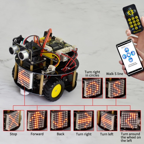
Our Tutorial
This tutorial is designed for everyone to play the smart robot. You will learn all the basic information about how to control this Arduino smart car with controller board, sensors and components. Easy to play and enjoy your time!
Is it great? Well, it's just the beginning of ARDUINO's journey. There are more and more awesome projects for you to explore. Furthermore, our KEYESTUDIO research and development team will continue to explore on this path, walking you through the basics up to complex projects. Hope that you can enjoy our works!
About keyestudio
Located in Shenzhen, the Silicon Valley of China, KEYES DIY ROBOT CO.,LTD is a thriving technology company dedicated to open-source hardware research and development, production and marketing. Keyestudio is a best-selling brand owned by KEYES Corporation, our product lines range from Arduino boards, shields, sensor modules, Raspberry Pi, micro:bit extension boards and smart car to complete starter kits designed for customers of any level to learn Arduino knowledge.
All of our products comply with international quality standards and are greatly appreciated in a variety of different markets throughout the world. For more details of our products, you can check it from the links below.
- Official Website: http://www.keyestudio.com/
- US Amazon storefront: http://www.amazon.com/shops/A26TCVWBQE4D9T
- CA Amazon storefront: http://www.amazon.ca/shops/A26TCVWBQE4D9T
- UK Amazon storefront: http://www.amazon.co.uk/shops/A39F7KX4U3W9JH
- DE Amazon storefront: http://www.amazon.de/shops/A39F7KX4U3W9JH
- FR Amazon storefront: http://www.amazon.de/shops/A39F7KX4U3W9JH
- ES Amazon storefront: http://www.amazon.de/shops/A39F7KX4U3W9JH
- IT Amazon storefront: http://www.amazon.de/shops/A39F7KX4U3W9JH
- US Amazon storefront: http://www.amazon.com/shops/APU90DTITU5DG
- CA Amazon storefront: http://www.amazon.ca/shops/APU90DTITU5DG
- JP Amazon storefront: http://www.amazon.jp/shops/AE9VWCCXQIC6J
Resource Download
- Download Libraries,Arduino Code,Mixly Code and softrware:
https://fs.keyestudio.com/KS0364
You can get more reference from below links:
- KEYESTUDIO WIKI: http://wiki.keyestudio.com/
- ARDUINO Software: https://www.arduino.cc/en/Main/OldSoftwareReleases#1.5.x
- Mixly Software WIN: https://drive.google.com/open?id=1CtP1bvZB-o4M5SfvIOOwFz-488gWsFTJ
- Mixly Software MAC: https://drive.google.com/open?id=1S0N_q73Dcyp85DjnbYm6MocZm3penOqU
- Assembly Video Link: http://video.keyestudio.com/KS0364/
Customer Service
As a continuous and fast growing technology company, we keep striving our best to offer you excellent products and quality service as to meet your expectation. We look forward to hearing from you and any of your critical comment or suggestion would be much valuable to us.
You can reach out to us by simply drop a line at Fennie@keyestudio.com
Thank you in advance.
