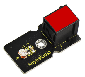
Ks0106 keyestudio EASY plug Photocell Sensor: Difference between revisions
Keyestudio (talk | contribs) No edit summary |
Keyestudio (talk | contribs) |
||
| (10 intermediate revisions by the same user not shown) | |||
| Line 4: | Line 4: | ||
A photoresistor or light-dependent resistor (LDR) or photocell is a light-controlled variable resistor. The principal is very simple. | A photoresistor or light-dependent resistor (LDR) or photocell is a light-controlled variable resistor. The principal is very simple. | ||
The resistance of photoresistor varies with incident light intensity. If the incident light intensity is high, the resistance decreases; if the light intensity is low, the resistance increases.<br> | The resistance of photoresistor varies with incident light intensity. If the incident light intensity is high, the resistance decreases; if the light intensity is low, the resistance increases.<br> | ||
keyestudio EASY Plug photocell sensor is a semiconductor, integrated with a photoresistor, easy to use and very convenient for wiring. <br> | keyestudio EASY Plug photocell sensor is a semiconductor, integrated with a photoresistor, easy to use and very convenient for wiring. <br> | ||
It has features of high sensitivity, quick response, spectral characteristic and R-value consistence.<br> | It has features of high sensitivity, quick response, spectral characteristic and R-value consistence.<br> | ||
It can be applied in light-sensitive detector circuits, intelligent switch design and light- and dark-activated switching circuits. <br> | It can be applied in light-sensitive detector circuits, intelligent switch design and light- and dark-activated switching circuits. <br> | ||
<span style= | This module should be used together with EASY plug control board.<br> | ||
<span style=color:red> '''Special Note:''' <br> | |||
The sensor/module is equipped with the RJ11 6P6C interface, compatible with our keyestudio EASY plug Control Board with RJ11 6P6C interface. <br> If you have the control board of other brands, it is also equipped with the RJ11 6P6C interface but has different internal line sequence, can’t be used compatibly with our sensor/module. </span><br> | |||
<br> | <br> | ||
| Line 26: | Line 28: | ||
==Connect It Up == | ==Connect It Up == | ||
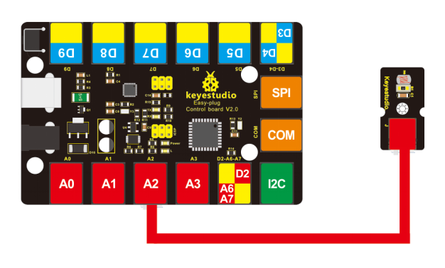
Connect the EASY Plug photocell sensor to control board using an RJ11 cable. Then connect the control board to your PC with a USB cable. | Connect the EASY Plug photocell sensor to control board using an RJ11 cable. Then connect the control board to your PC with a USB cable. | ||
<br>[[File:Ks0106-1-.png| | <br>[[File:Ks0106-1-.png|700px|frameless|thumb]]<br> | ||
<br> | <br> | ||
==Upload the Code== | ==Upload the Code== | ||
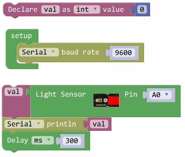
Below is an example code. Open or drag below code to [https://wiki.keyestudio.com/Getting_Started_with_Mixly Mixly Blocks] and upload. <br> | |||
< | <br>[[File:ks0398 4.1.png|600px|frameless|thumb]]<br> | ||
< | |||
<br> | <br> | ||
==What You Should See== | ==What You Should See== | ||
<br>[[File:ks0398 4-1.png|600px|frameless|thumb]]<br> | |||
<br> | |||
Done uploading the code, you should see the analog value change in accordance with how much light your photoresistor is sensing. | Done uploading the code, you should see the analog value change in accordance with how much light your photoresistor is sensing. | ||
<br>[[File: | <br>[[File:ks0398 4-2.png|600px|frameless|thumb]]<br> | ||
<br> | |||
==Controlling light brightness== | |||
'''Hookup Guide'''<br> | |||
Connect the EASY Plug photocell sensor and LED module to control board using RJ11 cable. | |||
<br>[[File:光敏灯.jpg|600px|frameless|thumb]]<br> | |||
<br> | |||
'''Test Code'''<br> | |||
Below is an example code for three LED modules experiment. | |||
<br>[[File:ks0398 4.2.png|600px|frameless|thumb]]<br> | |||
<br> | |||
'''What You Should See'''<br> | |||
The three LEDs are gradually brighter then gradually off one by one, circularly. <br> | |||
If it doesn’t, make sure you have assembled the circuit correctly and verified and uploaded the code to your board. | |||
<br>[[File:ks0398 4-3.png|600px|frameless|thumb]]<br> | |||
<br> | <br> | ||
==Resources == | ==Resources == | ||
https:// | https://fs.keyestudio.com/KS0106 | ||
<br> | <br> | ||
==Buy from == | ==Buy from == | ||
* | *[https://www.keyestudio.com/keyestudio-easy-plug-photoresistor-sensor-module-for-arduino-steam-p0072-p0072.html '''Official Website''' ] | ||
*[https://www.aliexpress.com/store/product/2016-New-Keyestudio-EASY-plug-Photoresistor-Sensor-Module-for-Arduino/1452162_32637445281.html?spm=2114.12010612.8148356.64.70f5484ethSftt Shop on aliexpress ] | |||
[[category:EASY Plug]] | [[category:EASY Plug]] | ||
Latest revision as of 15:54, 7 January 2021
Introduction
A photoresistor or light-dependent resistor (LDR) or photocell is a light-controlled variable resistor. The principal is very simple.
The resistance of photoresistor varies with incident light intensity. If the incident light intensity is high, the resistance decreases; if the light intensity is low, the resistance increases.
keyestudio EASY Plug photocell sensor is a semiconductor, integrated with a photoresistor, easy to use and very convenient for wiring.
It has features of high sensitivity, quick response, spectral characteristic and R-value consistence.
It can be applied in light-sensitive detector circuits, intelligent switch design and light- and dark-activated switching circuits.
This module should be used together with EASY plug control board.
Special Note:
The sensor/module is equipped with the RJ11 6P6C interface, compatible with our keyestudio EASY plug Control Board with RJ11 6P6C interface.
If you have the control board of other brands, it is also equipped with the RJ11 6P6C interface but has different internal line sequence, can’t be used compatibly with our sensor/module.
Specification
- Interface: Easy plug
- Sensor type: analog
- Working voltage: 5V
- Quick response
Technical Details
- Dimensions: 38mm*20mm*18mm
- Weight: 4.3g
Connect It Up
Connect the EASY Plug photocell sensor to control board using an RJ11 cable. Then connect the control board to your PC with a USB cable.
Upload the Code
Below is an example code. Open or drag below code to Mixly Blocks and upload.
What You Should See
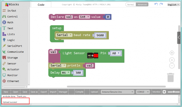
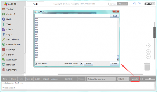
Done uploading the code, you should see the analog value change in accordance with how much light your photoresistor is sensing.
Controlling light brightness
Hookup Guide
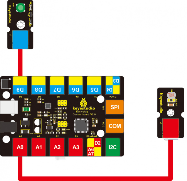
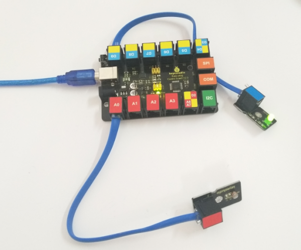
Connect the EASY Plug photocell sensor and LED module to control board using RJ11 cable.
Test Code
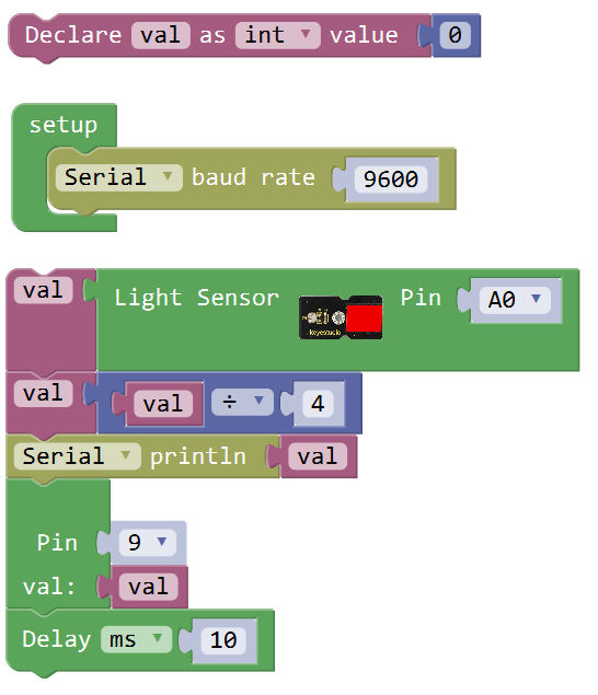
Below is an example code for three LED modules experiment.
What You Should See
The three LEDs are gradually brighter then gradually off one by one, circularly.
If it doesn’t, make sure you have assembled the circuit correctly and verified and uploaded the code to your board.
Resources
https://fs.keyestudio.com/KS0106
