Ks0053 keyestudio Color Sensor: Difference between revisions
Keyestudio (talk | contribs) No edit summary |
Keyestudio (talk | contribs) |
||
| (6 intermediate revisions by the same user not shown) | |||
| Line 25: | Line 25: | ||
<br> | <br> | ||
==Connection Diagram == | ==Connection Diagram == | ||
<br>[[File: | <br>[[File:Ks0053-1.png|700px|frameless|thumb]]<br> | ||
<br> | <br> | ||
There are in total 10 pins on this sensor. The following is the correct connection between this color sensor and Arduino UNO:<br> | There are in total 10 pins on this sensor. The following is the correct connection between this color sensor and Arduino UNO:<br> | ||
| Line 31: | Line 31: | ||
<br> | <br> | ||
==Sample Code == | ==Sample Code == | ||
| Line 37: | Line 38: | ||
#define S0 6 // Please notice the Pin's define | #define S0 6 // Please notice the Pin's define | ||
#define S1 5 | #define S1 5 | ||
#define S2 4 | #define S2 4 | ||
#define S3 3 | #define S3 3 | ||
#define OUT 2 | #define OUT 2 | ||
#define OE 7 | |||
#define LED 8 | |||
int g_count = 0; // count the frequecy | int g_count = 0; // count the frequecy | ||
int g_array[3]; // store the RGB value | int g_array[3]; // store the RGB value | ||
| Line 114: | Line 115: | ||
void setup() | void setup() | ||
{ | { | ||
pinMode(OE,OUTPUT); | |||
pinMode(LED,OUTPUT); | |||
digitalWrite(OE,LOW); | |||
digitalWrite(LED,LOW); | |||
TSC_Init(); | TSC_Init(); | ||
Serial.begin(9600); | Serial.begin(9600); | ||
| Line 128: | Line 133: | ||
Serial.println(g_SF[1]); | Serial.println(g_SF[1]); | ||
Serial.println(g_SF[2]); | Serial.println(g_SF[2]); | ||
} | } | ||
void loop() | void loop() | ||
| Line 136: | Line 142: | ||
delay(4000); | delay(4000); | ||
} | } | ||
</pre> | </pre> | ||
<br> | <br> | ||
==Resources == | ==Resources == | ||
| Line 145: | Line 153: | ||
http://video.keyestudio.com/ks0053/ | http://video.keyestudio.com/ks0053/ | ||
* ''' | * '''Library and Code:'''<br> | ||
https:// | https://fs.keyestudio.com/KS0053 | ||
<br> | |||
==Buy from== | ==Buy from== | ||
*[https://www.keyestudio.com/keyestudio-tcs3200-color-recognition-sensor-detector-module-for-arduino-p0354.html '''Official Website'''] | *[https://www.keyestudio.com/keyestudio-tcs3200-color-recognition-sensor-detector-module-for-arduino-p0354.html '''Official Website'''] | ||
*[https://www.aliexpress.com/store/product/FREE-SHIPPING-TCS230-TCS3200-Color-sensor-Color-recognition-module-for-arduino/1452162_2055138455.html?spm=2114.12010612.8148356.1.69a22462FhXG8C '''Aliexpress Store'''] | |||
*[https://www.aliexpress.com/store/product/FREE-SHIPPING-TCS230-TCS3200-Color-sensor-Color-recognition-module-for-arduino/1452162_2055138455.html?spm=2114.12010612.8148356.1.69a22462FhXG8C ''' | |||
[[Category: Sensor]] | [[Category: Sensor]] | ||
Latest revision as of 10:38, 9 September 2021
Introduction
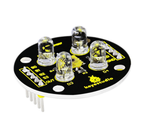
TCS3200 programmable color light-to-frequency converter applies to colorimeter measurement such as color printing, medical diagnosis, calibration of PC color monitor as well as process control and color coordination in oil paint, textile, cosmetics and printing material industries.
TCS3200 is built on the principle of three primary colors. Concretely speaking, TCS3200 allows only one specific primary color to go through and blocks other primary colors if a specific color filter was chosen.
For example, when red filter was chosen, only red light can pass through while blue and green lights will be blocked out, so that we can get the intensity of red light. The strength of blue and green lights can be got in the same way. Finally, By analyzing the light strength of these three color, we can recognize the color reflected onto TCS3200.

Specification
- Color Recognition Sensor Module
- Condition: New
- Chip: TCS230
- Input voltage: DC 3 ~ 5V
- Output frequency voltage: 0 ~ 5V
- Use high brightness white LEDs
- Can be connected directly to Microcontroller
- Static detection of the measured object color
- Best detection distance: 10mm
NOTE: Due to lighting effects, difference in monitor's brightness/ contrast settings etc, there could be some slight differences in the color tone between the pictures and the actual item!
Connection Diagram

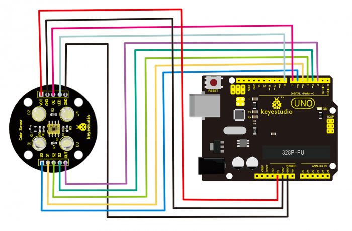
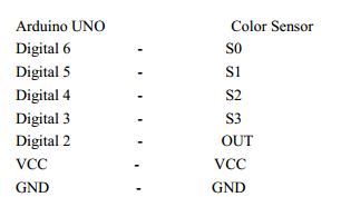
There are in total 10 pins on this sensor. The following is the correct connection between this color sensor and Arduino UNO:

Sample Code
#include <TimerOne.h>
#define S0 6 // Please notice the Pin's define
#define S1 5
#define S2 4
#define S3 3
#define OUT 2
#define OE 7
#define LED 8
int g_count = 0; // count the frequecy
int g_array[3]; // store the RGB value
int g_flag = 0; // filter of RGB queue
float g_SF[3]; // save the RGB Scale factor
// Init TSC230 and setting Frequency.
void TSC_Init()
{
pinMode(S0, OUTPUT);
pinMode(S1, OUTPUT);
pinMode(S2, OUTPUT);
pinMode(S3, OUTPUT);
pinMode(OUT, INPUT);
digitalWrite(S0, LOW); // OUTPUT FREQUENCY SCALING 2%
digitalWrite(S1, HIGH);
}
// Select the filter color
void TSC_FilterColor(int Level01, int Level02)
{
if(Level01 != 0)
Level01 = HIGH;
if(Level02 != 0)
Level02 = HIGH;
digitalWrite(S2, Level01);
digitalWrite(S3, Level02);
}
void TSC_Count()
{
g_count ++ ;
}
void TSC_Callback()
{
switch(g_flag)
{
case 0:
Serial.println("->WB Start");
TSC_WB(LOW, LOW); //Filter without Red
break;
case 1:
Serial.print("->Frequency R=");


Serial.println(g_count);
g_array[0] = g_count;
TSC_WB(HIGH, HIGH); //Filter without Green
break;
case 2:
Serial.print("->Frequency G=");
Serial.println(g_count);
g_array[1] = g_count;
TSC_WB(LOW, HIGH); //Filter without Blue
break;
case 3:
Serial.print("->Frequency B=");
Serial.println(g_count);
Serial.println("->WB End");
g_array[2] = g_count;
TSC_WB(HIGH, LOW); //Clear(no filter)
break;
default:
g_count = 0;
break;
}
}
void TSC_WB(int Level0, int Level1) //White Balance
{
g_count = 0;
g_flag ++;
TSC_FilterColor(Level0, Level1);
Timer1.setPeriod(1000000); // set 1s period
}
void setup()
{
pinMode(OE,OUTPUT);
pinMode(LED,OUTPUT);
digitalWrite(OE,LOW);
digitalWrite(LED,LOW);
TSC_Init();
Serial.begin(9600);
Timer1.initialize(); // defaulte is 1s
Timer1.attachInterrupt(TSC_Callback);
attachInterrupt(0, TSC_Count, RISING);
delay(4000);
for(int i=0; i<3; i++)
Serial.println(g_array[i]);
g_SF[0] = 255.0/ g_array[0]; //R Scale factor
g_SF[1] = 255.0/ g_array[1] ; //G Scale factor
g_SF[2] = 255.0/ g_array[2] ; //B Scale factor
Serial.println(g_SF[0]);
Serial.println(g_SF[1]);
Serial.println(g_SF[2]);

}
void loop()
{
g_flag = 0;
for(int i=0; i<3; i++)
Serial.println(int(g_array[i] * g_SF[i]));
delay(4000);
}
Resources
- Video:
http://video.keyestudio.com/ks0053/
- Library and Code:
https://fs.keyestudio.com/KS0053