Ks0064 keyestudio I2C 8x8 LED Matrix HT16K33: Difference between revisions
Keyestudio (talk | contribs) |
Keyestudio (talk | contribs) |
||
| (3 intermediate revisions by the same user not shown) | |||
| Line 79: | Line 79: | ||
== Resources == | == Resources == | ||
* [https:// | * [https://fs.keyestudio.com/KS0064 Click here to download the code libraries] | ||
* '''Video:''' http://video.keyestudio.com/ks0064/ | * '''Video:''' http://video.keyestudio.com/ks0064/ | ||
| Line 87: | Line 86: | ||
<br> | <br> | ||
== Buy From == | == Buy From == | ||
| Line 95: | Line 95: | ||
* [https://www.aliexpress.com/store/product/Keyestudio-Red-color-common-cathode-I2C-8-8-LED-dot-Matrix-module-HT16K33-for-arduino/1452162_32617887351.html?spm=2114.12010612.8148356.19.2ad52933y2jfa6 '''From Aliexpress'''] | * [https://www.aliexpress.com/store/product/Keyestudio-Red-color-common-cathode-I2C-8-8-LED-dot-Matrix-module-HT16K33-for-arduino/1452162_32617887351.html?spm=2114.12010612.8148356.19.2ad52933y2jfa6 '''From Aliexpress'''] | ||
* '''Shop on amazon store:''' https://www.amazon.com/dp/B0179AGI9K | |||
[[category:Module]] | [[category:Module]] | ||
Latest revision as of 09:35, 8 January 2021
Introduction
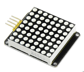
A fun way to make a small display is to use an 8x8 matrix or a 4-digit 7-segment display. Matrices like these are 'multiplexed' - to control 64 LEDs you need 16 pins. That's a lot of pins, and there are driver chips like the MAX7219 that can control a matrix for you, but there's a lot of wiring to set up and they take up a ton of space. After all, wouldn't it be awesome if you could control a matrix without tons of wiring? That's where these lovely LED matrix backpacks come in.
The matrices use the constant-current drivers for ultra-bright, consistent color, 1/16 step display dimming, all via a simple I2C interface.
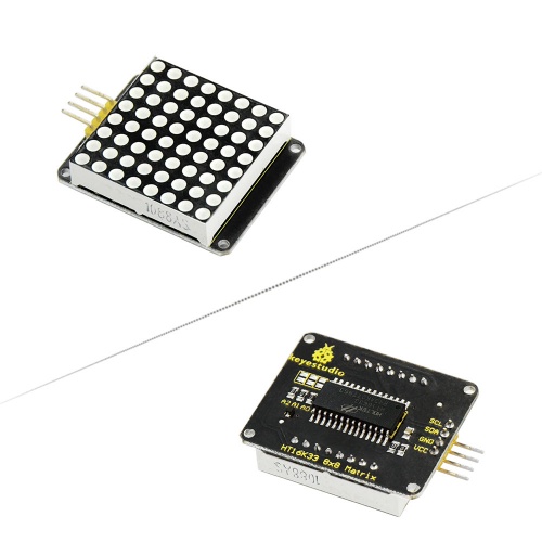
Features
- 8 rows and 8 cols LED matrix
- Driven by HT16K33 chip
- Access to I2C communication pins
- Occupy less IO ports of microcontrollers
- Easy connection and available for more experiment extensions
Parameters
- Input voltage: 5V
- Rated input frequency: 400KHZ
- Input power: 2.5W
- Input current: 500mA
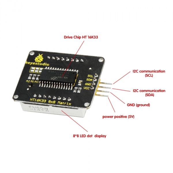
Pinout
Wire it Up
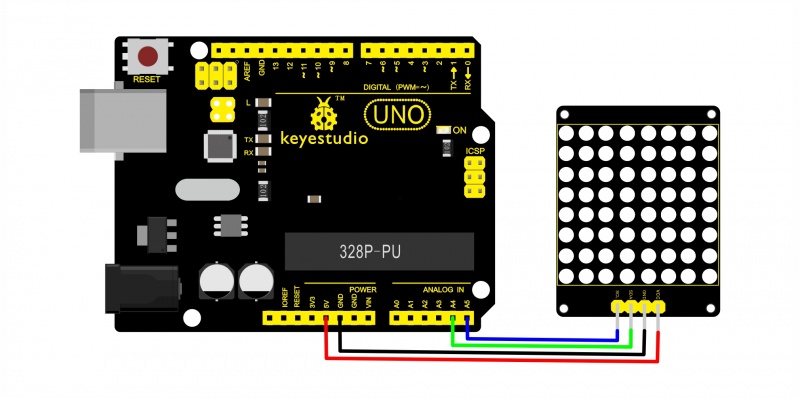
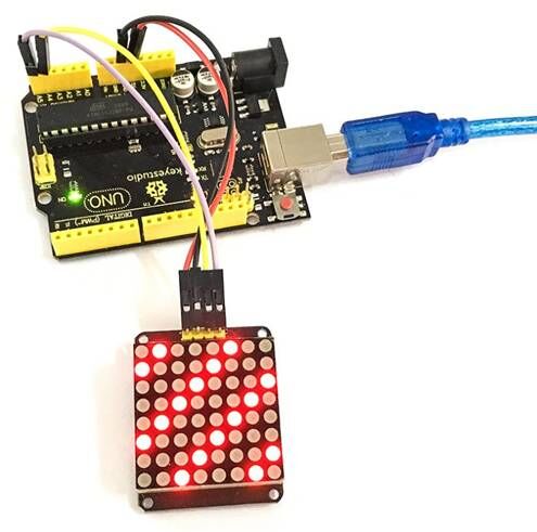
Connect the SCL pin to Analog A5, SDA pin to Analog A4 port; Connect VCC pin to 5V port, GND pin to GND.
Sample Code
Below is an example code, you can upload it to Arduino IDE.
#include <Wire.h>
#include "Adafruit_LEDBackpack.h"
#include "Adafruit_GFX.h"
#ifndef _BV
#define _BV(bit) (1<<(bit))
#endif
Adafruit_LEDBackpack matrix = Adafruit_LEDBackpack();
uint8_t counter = 0;
void setup() {
  Serial.begin(9600);
  Serial.println("HT16K33 test");
  matrix.begin(0x70);  // pass in the address
}
void loop() {
  // paint one LED per row. The HT16K33 internal memory looks like
  // a 8x16 bit matrix (8 rows, 16 columns)
  for (uint8_t i=0; i<8; i++) {
// draw a diagonal row of pixels

    matrix.displaybuffer[i] = _BV((counter+i) % 16) | _BV((counter+i+8) % 16)  ;
  }
  // write the changes we just made to the display
  matrix.writeDisplay();
  delay(100);
 counter++;
  if (counter >= 16) counter = 0;
}
Note: before upload the code, you should place the library inside Arduino libraries. Or else fail to compile it.
You can download the code libraries from the link below:
https://drive.google.com/open?id=1FUTIwsfGdxTXXgYDGxI7U2VoP0g3G-2L
Example Result
Done wiring and powered up, upload well the code to UNO board, you will see the dot matrix display the image shown below.
Resources
Buy From
- Shop on amazon store: https://www.amazon.com/dp/B0179AGI9K
