Ks0193 keyestudio Self-balancing Car: Difference between revisions
Keyestudio (talk | contribs) No edit summary |
Keyestudio (talk | contribs) |
||
| (127 intermediate revisions by the same user not shown) | |||
| Line 4: | Line 4: | ||
<br> | <br> | ||
==Overview == | ==Overview == | ||
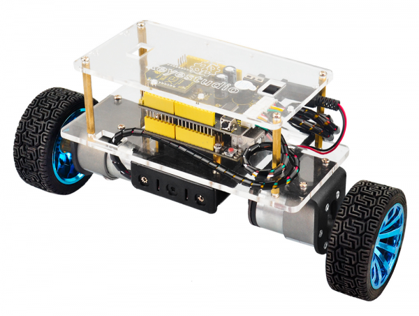
How to DIY a mini balance car on your own? This balance car kit is based on Arduino development platform. We mainly use | How to DIY a mini balance car on your own? This balance car kit is based on Arduino development platform. We mainly use REV4 as core and balance shield with built-in MPU-6050 as drive board to test the car body posture. <br> | ||
The balance shield comes with a Bluetooth interface, fully compatible with the Bluetooth XBee module (only compatible with | The balance shield comes with a Bluetooth interface, fully compatible with the Bluetooth XBee module (only compatible with Android system).<br> | ||
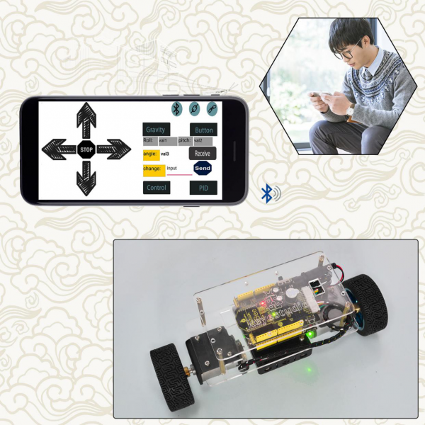
When connecting to Bluetooth, you can easily control the moving direction of balance car with Bluetooth APP, making a variety of unique postures.<br> | When connecting to Bluetooth, you can easily control the moving direction of balance car with Bluetooth APP, making a variety of unique postures.<br> | ||
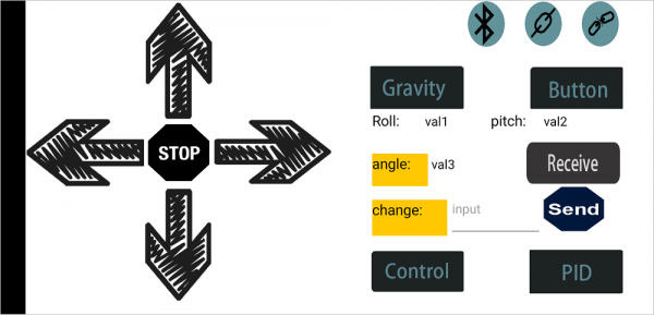
To facilitate the operation control, Bluetooth APP has both key and gravity control modes. <br> | To facilitate the operation control, Bluetooth APP has both key and gravity control modes. <br> | ||
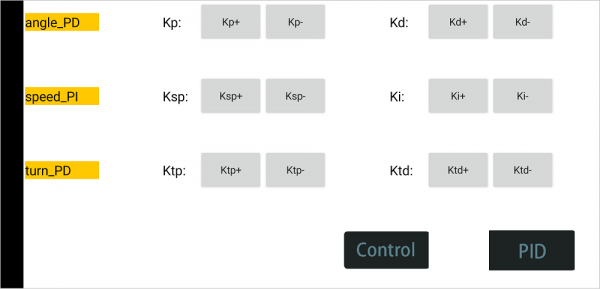
Moreover, it adds the function of adjusting the balance angle and PID parameters as well, so you can perfectly adjust and control the balance car. <br> | Moreover, it adds the function of adjusting the balance angle and PID parameters as well, so you can perfectly adjust and control the balance car. <br> | ||
No need to worry how to play it. We can provide you with all assembly components, as well as the corresponding installation, debugging method and program.<br> | No need to worry how to play it. We can provide you with all assembly components, as well as the corresponding installation, debugging method and program.<br> | ||
<br> | <br> | ||
== Operation Principle == | == Operation Principle == | ||
The self-balancing car uses the power of the car body to maintain the relative balance, which is a process of dynamic balance. <br> | The self-balancing car uses the power of the car body to maintain the relative balance, which is a process of dynamic balance. <br> | ||
| Line 29: | Line 30: | ||
== Parameters of balance car == | == Parameters of balance car == | ||
<br> | <br> | ||
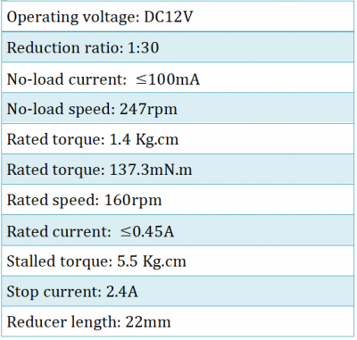
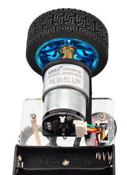
* 1.Motor parameters: | * 1.Motor parameters: | ||
[[File:KS0193-图片4.png|400px|frameless|thumb]]<br> | |||
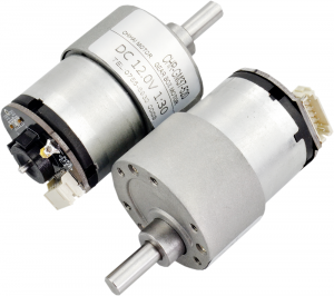
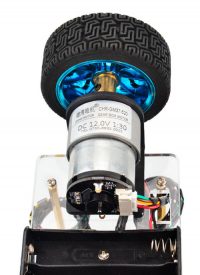
[[image:KS0193-图片5.png|thumb|300px|right|Motor]] <br> | |||
* 2.Working voltage: DC 9-12V | * 2.Working voltage: DC 9-12V | ||
* 3.Motor drive chip: TB6612FNG | * 3.Motor drive chip: TB6612FNG | ||
| Line 37: | Line 38: | ||
* 5.Comes with power control switch | * 5.Comes with power control switch | ||
* 6.Comes with Bluetooth control switch for controlling serial communication | * 6.Comes with Bluetooth control switch for controlling serial communication | ||
<br> | <br> | ||
<span style=color:red> '''Pay special attention to:''' <br> | <span style=color:red> '''Pay special attention to:''' <br> | ||
| Line 43: | Line 43: | ||
When upload the source code, must turn the slide switch OFF; otherwise, code uploading will fail. <br> | When upload the source code, must turn the slide switch OFF; otherwise, code uploading will fail. <br> | ||
When connecting to the Bluetooth module, should turn the slide switch ON.<br> | When connecting to the Bluetooth module, should turn the slide switch ON.<br> | ||
<br>[[File:KS0193-图片6.png| | <br>[[File:KS0193-图片6.png|500px|frameless|thumb]]<br> | ||
<br> | <br> | ||
== Kit List == | == Kit List == | ||
The kit packaging contains all electronic components for this self-balancing car. As you work your way through each project, you will learn how to control the car. <br> | The kit packaging contains all electronic components for this self-balancing car. As you work your way through each project, you will learn how to control the car. <br> | ||
{| width="80%" cellspacing="0" border="1" | |||
|- | |||
! align="center" scope="col" | No. | |||
! align="center" scope="col" | Components | |||
! align="center" scope="col" | Quantity | |||
! align="center" scope="col" | Picture | |||
|- | |||
| align="center" | 1 | |||
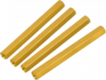
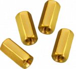
| align="center" | Dual-pass M3*45MM hex copper pillar | |||
| align="center" | 4 | |||
| align="center" | <br>[[File:KS0193-图片7.png|150px|frameless|thumb]]<br> | |||
|- | |||
| align="center" | 2 | |||
| align="center" | Dual-pass M3*10MM hex copper pillar | |||
| align="center" | 4 | |||
| align="center" | <br>[[File:KS0193-图片8.png|150px|frameless|thumb]]<br> | |||
|- | |||
| align="center" | 3 | |||
| align="center" | Black M4*6 cross screw | |||
| align="center" | 2 | |||
| align="center" | <br>[[File:KS0193-图片9.png|150px|frameless|thumb]]<br> | |||
|- | |||
| align="center" | 4 | |||
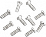
| align="center" | M3*6MM round head screw | |||
| align="center" | 6 | |||
| align="center" | <br>[[File:KS0193-图片10.png|150px|frameless|thumb]]<br> | |||
|- | |||
| align="center" | 5 | |||
| align="center" | M3*8MM round head screw | |||
| align="center" | 10 | |||
| align="center" | <br>[[File:KS0193-图片11.png|150px|frameless|thumb]]<br> | |||
|- | |||
| align="center" | 6 | |||
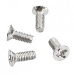
| align="center" | M3*8MM flat head cross screw | |||
| align="center" | 4 | |||
| align="center" | <br>[[File:KS0193-图片12.png|150px|frameless|thumb]]<br> | |||
|- | |||
| align="center" | 7 | |||
| align="center" | M3*12MM flat head cross screw | |||
| align="center" | 2 | |||
| align="center" | <br>[[File:KS0193-图片13.png|150px|frameless|thumb]]<br> | |||
|- | |||
| align="center" | 8 | |||
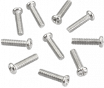
| align="center" | M3*12MM round head screw | |||
| align="center" | 10 | |||
| align="center" | <br>[[File:KS0193-图片14.png|150px|frameless|thumb]]<br> | |||
|- | |||
| align="center" | 9 | |||
| align="center" | M3 nickel plating nut | |||
| align="center" | 12 | |||
| align="center" | <br>[[File:KS0193-图片15.png|150px|frameless|thumb]]<br> | |||
|- | |||
| align="center" | 10 | |||
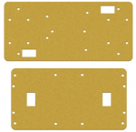
| align="center" | Acrylic plate pack of 2pcs | |||
| align="center" | 1 | |||
| align="center" | <br>[[File:KS0193-图片16.png|150px|frameless|thumb]]<br> | |||
|- | |||
| align="center" | 11 | |||
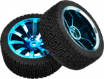
| align="center" | Black+blue outer diameter 68mm thickness 26mm wheel | |||
| align="center" | 2 | |||
| align="center" | <br>[[File:KS0193-图片17.png|150px|frameless|thumb]]<br> | |||
|- | |||
| align="center" | 12 | |||
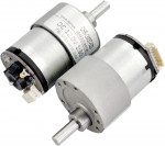
| align="center" | GM37-520 DC gear motor with hall encoder 12V,1:30,with type L holders | |||
| align="center" | 2 | |||
| align="center" | <br>[[File:KS0193-图片5.png|150px|frameless|thumb]]<br> | |||
|- | |||
| align="center" | 13 | |||
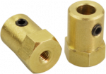
| align="center" | 6MM hole*18MM length Copper hex coupler | |||
| align="center" | 2 | |||
| align="center" | <br>[[File:KS0193-图片18.png|150px|frameless|thumb]]<br> | |||
|- | |||
| align="center" | 14 | |||
| align="center" | Double-head 6pin PH2.0 30CM connector wire | |||
| align="center" | 2 | |||
| align="center" | <br>[[File:KS0193-图片19.png|150px|frameless|thumb]] [[File:KS0193-图片19.png|150px|frameless|thumb]] <br> | |||
|- | |||
| align="center" | 15 | |||
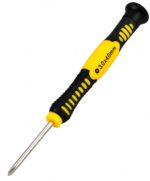
| align="center" | Yellow-black handle 3*40MM Phillips screwdriver | |||
| align="center" | 1 | |||
| align="center" | <br>[[File:KS0193-图片20.png|150px|frameless|thumb]]<br> | |||
|- | |||
| align="center" | 16 | |||
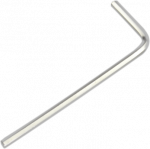
| align="center" | Type L M2 nickel plating inner hex wrench | |||
| align="center" | 1 | |||
| align="center" | <br>[[File:KS0193-图片21.png|150px|frameless|thumb]]<br> | |||
|- | |||
| align="center" | 17 | |||
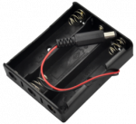
| align="center" | 18650 3-cell AA battery case with 15CM lead+plug | |||
<span style=color:red> (18650 battery not included) </span > <br> | |||
| align="center" | 1 | |||
| align="center" | <br>[[File:KS0193-图片22.png|150px|frameless|thumb]]<br> | |||
|- | |||
| align="center" | 18 | |||
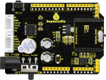
| align="center" | Keyestudio Balance Shield V3 (black and eco-friendly) | |||
| align="center" | 1 | |||
| align="center" | <br>[[File:KS0193-图片6.png|150px|frameless|thumb]]<br> | |||
|- | |||
| align="center" | 19 | |||
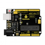
| align="center" | Keyestudio REV4 main board | |||
| align="center" | 1 | |||
| align="center" | <br>[[File:KS0470-1-1(2).jpg|150px|frameless|thumb]]<br> | |||
|- | |||
| align="center" | 20 | |||
| align="center" | AM/BM transparent blue OD:5.0 L=50cm USB cable | |||
| align="center" | 1 | |||
| align="center" | <br>[[File:80-49.png|400px|frameless|thumb]]<br> | |||
|- | |||
| align="center" | 21 | |||
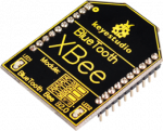
| align="center" | Keyestudio Bluetooth XBee HC-06 | |||
| align="center" | 1 | |||
| align="center" | <br>[[File:KS0193-图片23.png|150px|frameless|thumb]]<br> | |||
|- | |||
| align="center" | 22 | |||
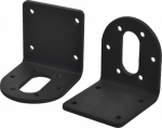
| align="center" | Motor iron holder | |||
| align="center" | 2 | |||
| align="center" | <br>[[File:KS0193-图片24.png|150px|frameless|thumb]]<br> | |||
|- | |||
| align="center" | 23 | |||
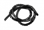
| align="center" | Black winding tube | |||
| align="center" | 1 | |||
| align="center" | <br>[[File:KS0193-图片25.png|150px|frameless|thumb]]<br> | |||
|- | |||
|} | |||
<br> | |||
== Resources == | |||
'''All Info.Download:''' <br> | |||
https://1drv.ms/u/s!ArhgRvK6-RyJhGZP5VY85WVtDBhL?e=BLmybl | |||
<br> | |||
== Assembly Steps == | |||
(1) Prepare all the components shown below. <br> | |||
<br>[[File:193-1.jpg|500px|frameless|thumb]]<br> | |||
<br> | |||
(2) To begin with, we start to install the bottom Acrylic plate.<br> | |||
Find out the parts below: <br> | |||
* Bottom Acrylic plate | |||
* Dual-pass M3*10MM hex copper pillar x 4pcs | |||
* M3*8MM screw x 4pcs | |||
* M3*12MM flat head screw x 2pcs | |||
* M3 nickel plating nut x 2pcs | |||
* Battery case | |||
<br>[[File:KS0193-图片27.png|500px|frameless|thumb]]<br> | |||
<br> | |||
We are now going to mount the battery case and copper pillars on the Acrylic plate. <br> | |||
Fix the 4pcs M3*10MM copper pillar onto the Acrylic plate using 4pcs M3*8MM screws. <br> | |||
<br>[[File:KS0193-图片28.png|500px|frameless|thumb]]<br> | |||
<br> | |||
Then Mount the battery case on the Acrylic plate using 2pcs M3*12MM flat head screws and 2pcs M3 nickel plating Nuts. | |||
<br>[[File:KS0193-图片29.png|500px|frameless|thumb]]<br> | |||
<br> | |||
(3) Next, move on to install the motor and wheel onto bottom Acrylic plate. <br> | |||
Find out the parts below: <br> | |||
* Bottom Acrylic plate mounted with battery case | |||
* M3*12MM round-head screw x 8pcs | |||
* M3 nickel plating nut x 8pcs | |||
* M4*6MM black screw x 2pcs | |||
* Two wheels | |||
* Two black connectors | |||
* Two motors | |||
* Two copper hex couplers | |||
* M2 wrench Type L | |||
<br>[[File:KS0193-图片30.png|500px|frameless|thumb]]<br> | |||
<br> | |||
Go to mount the two black connectors onto the Acrylic plate using 8pcs M3*12MM round-head screws and 8pcs M3 nickel plating nuts. Shown below. | |||
<br>[[File:KS0193-图片31.png|500px|frameless|thumb]]<br> | |||
Each motor is equipped with six screws in the bag. Go to mount the two motors on the black connectors using the screws. | |||
<br>[[File:KS0193-图片32.png|500px|frameless|thumb]]<br> | |||
Screw each copper hex couplers with two screws. Then fix the two copper couplers on the two motors using a wrench. | |||
<br>[[File:KS0193-图片33.png|500px|frameless|thumb]]<br> | |||
<br>[[File:KS0193-图片34.png|500px|frameless|thumb]]<br> | |||
Finally mount the two wheels to the two hex copper couplers using 2pcs M4*6MM black screws. | |||
<br>[[File:KS0193-图片35.png|500px|frameless|thumb]]<br> | |||
<br> | |||
Up to now, the bottom motor wheel are installed well! <br> | |||
<br>[[File:KS0193-图片36.png|500px|frameless|thumb]]<br> | |||
<br> | |||
(4) The final step is to install the control board and the top Acrylic plate. <br> | |||
* Top Acrylic plate | |||
* REV4 control board | |||
* keyestudio balance shield | |||
* Bluetooth XBee module HC-06 | |||
* M3*6MM round-head screw x 3pcs | |||
* M3*45MM copper pillar x 4pcs | |||
* M3*8MM round-head screw x 8pcs | |||
* 6pin 30CM connector wire x 2pcs | |||
<br>[[File:193.jpg|500px|frameless|thumb]]<br> | |||
<br> | |||
Go to screw the REV4 control board onto the 4pcs M3*10MM copper pillars mounted on the Acrylic plate with 3pcs M3*6MM round-head screws. | |||
<br>[[File:193-2.jpg|500px|frameless|thumb]]<br> | |||
Then stack the keyestudio balance shield onto REV4 control board. And plug the Bluetooth XBee module HC-06 into the balance shield. | |||
<br>[[File:-.png|500px|frameless|thumb]]<br> | |||
Go to connect the motor to the balance shield using 6pin PH2.0 30CM connector wire. Simply connect the motor to the nearest motor connector. | |||
<br>[[File:KS0193-图片40.png|500px|frameless|thumb]]<br> | |||
After that, screw the 4pcs M3*45MM copper pillars on the Acrylic plate with 4pcs M3*8MM round head screws. And connect well the battery plug to DC black jack of REV4. | |||
<br>[[File:KS0193-图片41.png|500px|frameless|thumb]]<br> | |||
The back view is showed below: | |||
<br>[[File:KS0193-图片42.png|500px|frameless|thumb]]<br> | |||
The final part is to install the top Acrylic plate onto the 4pcs M3*45MM copper pillars with 4pcs M3*8MM round-head screws. | |||
<br>[[File:KS0193-图片43.png|500px|frameless|thumb]]<br> | |||
Congrats! The balance car is installed well. | |||
<br>[[File:KS0193-图片1.png|500px|frameless|thumb]]<br> | |||
<br> | |||
== Project 1: Getting Started with Main Board and ARDUINO == | |||
=== The REV4 Control Board === | |||
<br>[[image:KS0470-1-1(2).jpg|600px|]]<br> | |||
When it comes to using the REV4 as core of our robot, the REV4 is the best board to get started with electronics and coding. If this is your first experience tinkering with the platform, the REV4 is the most robust board you can start playing with. <br> | |||
<br> | |||
Well, let's at first have a look at this REV4 board. | |||
<br>[[Image:KS0341 引脚标图.jpg|800px|frameless]]<br> | |||
{| width="80%" cellspacing="0" border="1" | |||
|- | |||
| align="center" | [[Image:KS0313 5.1-1.png|500px|frameless]] | |||
| align="light" | '''USB Connection''' | |||
Arduino board can be powered via USB connector. Or you can program the board via the USB port.<br> | |||
|- | |||
| align="center" | [[Image:KS0313 5.1-2.png|500px|frameless]] | |||
| align="light" | '''DC Power Jack''' | |||
Arduino board can be supplied with power from the DC power jack | |||
|- | |||
| align="center" | [[Image:KS0313 5.1-3.png|500px|frameless]] | |||
| align="light" | '''Voltage Regulator''' | |||
To control the voltage provided to the Arduino board, as well as to stabilize the DC voltage used by the processor and other components. | |||
|- | |||
| align="center" | [[Image:KS0313 5.1-4.png|500px|frameless]] | |||
| align="light" | '''Crystal Oscillator''' | |||
How does Arduino calculate time? by using a crystal oscillator. | |||
The number printed on the top of the Arduino crystal is 16.000H9H. It tells us that the frequency is 16,000,000 Hertz or 16MHz. | |||
|- | |||
| align="center" | [[Image:KS0313 5.1-5.png|500px|frameless]] | |||
| align="light" | '''Arduino RESET''' | |||
You can reset your Arduino board, for example, start the program from the very beginning. Firstly, use the RESET button(17). Or you can connect an external reset button to Arduino pin 5 labeled RESET | |||
|- | |||
| align="center" | [[Image:KS0313 5.1-6.png|500px|frameless]] | |||
| align="light" | '''Pin Header(3.3V,5V,GND,Vin''' | |||
[[Image:KS0313 5.1-7.png|500px|frameless]]3.3V - provides 3.3V output voltage <br> | |||
[[Image:KS0313 5.1-8.png|500px|frameless]]5V - provides 5V output voltage<br> | |||
Using 3.3 volts and 5 volts, most components can normally operate with Arduino board together.<br> | |||
[[Image:KS0313 5.1-9.png|500px|frameless]]GND(Ground pins)- two GND headers on Arduino, each of which can be used for circuit ground.<br> | |||
[[Image:KS0313 5.1-10.png|500px|frameless]]Vin - You can supply an external power (like AC power supply) through this pin to Arduino board. | |||
|- | |||
| align="center" | [[Image:KS0313 5.1-11.png|500px|frameless]] | |||
| align="light" | '''Analog Pins''' | |||
Arduino REV4 board has 6 analog inputs, labeled A0 through A5. These pins can read the signal from analog sensors (such as humidity sensor or temperature sensor), and convert it into the digital value that can read by microcontrollers) | |||
|- | |||
| align="center" | [[Image:KS0313 5.1-12.png|500px|frameless]] | |||
| align="light" | '''Microcontroller ''' | |||
Each Arduino board has its own microcontroller. You can regard it as the brain of your board.<br> | |||
The main IC (integrated circuit) on the Arduino is slightly different from the panel pair. Microcontrollers are usually from ATMEL. Before you load a new program from the Arduino IDE, you must know what IC is on your board. This information can be checked at the top of IC. | |||
|- | |||
| align="center" | [[Image:KS0313 5.1-13.png|500px|frameless]] | |||
| align="light" | '''ICSP (In-Circuit Serial Programming) Header''' | |||
In most case, ICSP is the AVR, an Arduino micro-header consisting of MOSI, MISO, SCK, RESET, VCC, and GND.It is often called the SPI (serial peripheral interface) and can be considered an "extension" of the output.In fact, slave the output devices under the SPI bus host. | |||
|- | |||
| align="center" | [[Image:KS0313 5.1-14.png|500px|frameless]] | |||
| align="light" | '''Power LED Indicator''' | |||
Powering the Arduino, LED on means that your circuit board is correctly powered on. If LED is off, connection is wrong. | |||
|- | |||
| align="center" | [[Image:KS0313 5.1-15.png|500px|frameless]] | |||
| align="light" | '''TX and RX LED ''' | |||
Onboard you can find two labels: RX(receive ) and TX (transmit)<br> | |||
First appear on digital pin 0 and 1 for serial communication; <br> | |||
Besides, the RX LED on the board will flash in different speed when serial data is being transmitted. The flash speed depends on the baud rate set by board. And RX LED will also flash during the receiving process. | |||
|- | |||
| align="center" | [[Image:KS0313 5.1-16.png|500px|frameless]] | |||
| align="light" | '''Digital I/O''' | |||
Arduino REV4 has 14 digital input/output pins (of which 6 can be used as PWM outputs). These pins can be configured as digital input pin to read the logic value (0 or 1). Or used as digital output pin to drive different modules like LED, relay, etc. The pin labeled “〜” can be used to generate PWM. | |||
|- | |||
| align="center" | [[Image:KS0313 5.1-17.png|500px|frameless]] | |||
| align="light" | '''AREF''' | |||
Reference voltage( 0-5V) for the analog inputs. Used with analogReference(). | |||
|- | |||
|} | |||
<br> | |||
=== The Balance Car Shield === | |||
<br>[[File:KS0193-图片6.png|400px|frameless|thumb]]<br> | |||
The balance shield is an important part for this balance car. With it, you can DIY the balance car more simple. | |||
It is fully compatible with REV4 board; just stack it onto the control board. <br> | |||
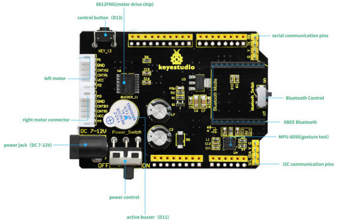
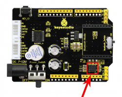
The balance shield comes with a 6612FNG chip for driving two DC motors; two white connectors for connecting DC motor; a DC power jack for powering on the shield and REV4; <br> | |||
Also comes with a large slide switch for controlling the power switch; a MPU-6050 for testing the posture; a XBEE Bluetooth interface for connecting Bluetooth module to communicate with Android devices; a small slide switch for controlling Bluetooth module’s communication; also comes with a button and an active buzzer. <br> | |||
The control pins of REV4 are all brought out as female header on the shield; the serial port and I2C communication pins are brought out as pin headers.<br> | |||
<span style=color:red> Note: connect the motor to the motor’s connector on the shield. </span> <br> | |||
<br>[[File:KS0193-图片1.png|500px|frameless|thumb]]<br> | |||
'''PINOUTS:''' | |||
<br>[[File:KS0193-图片44.png|700px|frameless|thumb]]<br> | |||
<br> | |||
===Installing Arduino IDE=== | |||
When you get the REV4 development board, first you should install the software and driver of Arduino. You can see all the Arduino software versions from the link below: <br> | |||
https://www.arduino.cc/en/Main/OldSoftwareReleases#1.5.x <br> | |||
Or you can browse the ARDUINO website at this link, https://www.arduino.cc, pop up the following interface. | |||
<br>[[Image:KS0313-1.png|600px|frameless]]<br> | |||
<br> | |||
Then click the SOFTWARE on the browse bar, you will have two options ONLINE TOOLS and DOWNLOADS. | |||
<br>[[Image:KS0313-2.png|600px|frameless]]<br> | |||
<br> | |||
Click DOWNLOADS, it will appear the latest software version of ARDUINO 1.8.5 shown as below. | |||
<br>[[Image:KS0313-3.png|600px|frameless]]<br> | |||
<br> | |||
In this software page, on the right side you can see the version of development software for different operating systems. So ARDUINO has a rather powerful compatibility. You should download the software that is compatible with the operating system of your computer.<br> | |||
In our project, we will take WINDOWS system as an example here. There are also two options under Windows system, one is installed version, the other is non-installed version. | |||
For simple installed version, first click Windows Installer, you will get the following page.<br> | |||
<br>[[Image:KS0313-4.png|600px|frameless]]<br> | |||
<br>[[Image:KS0313-5.png|600px|frameless]]<br> | |||
<br> | |||
This way you just need to click JUST DOWNLOAD, then click the downloaded file to install it. <br> | |||
For non-installed version, first click Windows ZIP file, you will also get the pop-up interface as the above figure.<br> | |||
Click JUST DOWNLOAD, and when the ZIP file is downloaded well to your computer, you can directly unzip the file and then click the icon of ARDUINO program to start it. <br> | |||
<br> | |||
===Installing Arduino (Windows)=== | |||
Install Arduino with the exe. Installation package | |||
<br>[[File:Arduino Setup 1.jpg|800px|frameless|thumb]]<br> | |||
Click“I Agree”to see the following interface. | |||
<br>[[File:Arduino Setup 2.jpg|800px|frameless|thumb]]<br> | |||
Click “Next”. Pop up the interface below. | |||
<br>[[File:Arduino Setup 3.jpg|800px|frameless|thumb]]<br> | |||
You can press Browse… to choose an installation path or directly type in the directory you want.<br> | |||
Then click “Install” to initiate installation. | |||
<br>[[File:Arduino Setup 4.jpg|800px|frameless|thumb]]<br> | |||
Wait for the installing process, if appear the interface of Window Security, just continue to click Install to finish the installation. | |||
<br>[[File:Arduino1.5.6- setup 5.png|800px|frameless|thumb]]<br> | |||
All right, up to now, you have completed the Arduino setup! The following icon will appear on your PC desktop. | |||
<br>[[Image:Ks0313图片1.png|600px|frameless]]<br> | |||
Double-click the icon of Arduino to enter the desired development environment shown as below. | |||
<br>[[Image:Ks0436-9.png|600px|frameless]]<br> | |||
<br> | |||
===Installing Driver=== | |||
Next, we will introduce the driver installation of REV4 development board. The driver installation may have slight differences in different computer systems. So in the following let’s move on to the driver installation in the WIN 7 system. <br> | |||
The Arduino folder contains both the Arduino program itself and the drivers that allow the Arduino to be connected to your computer by a USB cable. Before we launch the Arduino software, you are going to install the USB drivers.<br> | |||
Plug one end of your USB cable into the Arduino and the other into a USB socket on your computer.<br> | |||
When you connect REV4 board to your computer at the first time, right click the icon of your “Computer” —>for “Properties”—> click the “Device manager”, under “Other Devices”, you should see an icon for“Unknown device” with a little yellow warning triangle next to it. This is your Arduino.<br> | |||
<br>[[Image:Driver 1.png|600px|frameless]]<br> | |||
Then right-click on the device and select the top menu option (Update Driver Software...) shown as the figure below.. | |||
<br>[[Image:Driver 2.png|600px|frameless]]<br> | |||
It will then be prompted to either “Search Automatically for updated driver software” or “Browse my computer for driver software”. Shown as below. In this page, select “Browse my computer for driver software”. | |||
<br>[[Image:Driver 3.png|600px|frameless]]<br> | |||
After that, select the option to browse and navigate to the “drivers” folder of Arduino installation. | |||
<br>[[Image:KS0286-4.png|800px|frameless]]<br> | |||
Click “Next” and you may get a security warning, if so, allow the software to be installed. Shown as below. | |||
<br>[[Image:Driver 5.png|600px|frameless]]<br> | |||
Once the software has been installed, you will get a confirmation message. Installation completed, click “Close”. | |||
<br>[[Image:Driver 6.png|600px|frameless]]<br> | |||
Up to now, the driver is installed well. Then you can right click “Computer” —>“Properties”—>“Device manager”, you should see the device as the figure shown below. | |||
<br>[[Image:Driver 7.png|600px|frameless]]<br> | |||
<br> | |||
=== Example Use of ARDUINO IDE === | |||
'''STEP 1: Open Arduino'''<br> | |||
In the previous, we have introduced the driver installation of REV4 development board. So this time let’s first have basic understanding of the development environment of ARDUINO. After that, you will learn how to upload the program to Arduino board. <br> | |||
First of all, open the unzipped folder of ARDUINO development software and click icon of ARDUINO to open the software, as the figure shown below. | |||
<br>[[Image:Arduino folder.png|600px|frameless]]<br> | |||
<br> | |||
'''STEP 2: Build Projects'''<br> | |||
When open the Arduino software, you will have two options as below:<br> | |||
*Build a new project<br> | |||
*Open an exiting project example <br> | |||
If you want to build a new project, please select “File”→then click “New”, you will see the software interface as follows.<br> | |||
<br>[[Image:Arduino 1-8-5 new.png|400px|frameless]][[Image:0313 箭头.png|500px|frameless]][[Image:Arduino 1-8-5 new2.png|400px|frameless]]<br> | |||
<br> | |||
If you want to open an example project, please select File→Example→Basics→Blink. Shown below.<br> | |||
<br>[[Image:Arduino 1-8-5 example.png|450px|frameless]] [[Image:0313 箭头.png|500px|frameless]][[Image:Arduino 1-8-5 example2.png|400px|frameless]]<br> | |||
<br> | |||
'''STEP 3: Select Arduino Board'''<br> | |||
On the Arduino software, you should click Tools→Board , select the correct board. Here in our tutorial we should select Arduino UNO. Shown as below. | |||
<br>[[Image:Arduino 1-8-5 board.png|500px|frameless]]<br> | |||
<br> | |||
'''STEP 4: Select Serial Port'''<br> | |||
If you are not sure which port is correct, at first directly open the Control Panel of your computer, then click to open Device Manager, you can check the COM port here. Shown as below. <br> | |||
<br>[[Image:Driver 7.png|600px|frameless]]<br> | |||
<br> | |||
Then you should click Tools→Serial Port. It may be COM3 or higher (COM1 and COM2 are usually reserved as hardware serial port). | |||
<br>[[Image:Arduino 1-8-5 port.png|500px|frameless]]<br> | |||
<br> | |||
'''STEP 5: Upload the Code to Your Board'''<br> | |||
Before showing you how to upload the code to your board, first of all let me introduce the function of each icon on the Tool bar of Arduino IDE. Look at the picture showed below. | |||
<br>[[Image:图片1- arduino toolbar.png|500px|frameless]]<br> | |||
{| class="wikitable" cellpadding="1" cellspacing="1" | |||
|- | |||
!scope="row" |[[Image:IDE 1.png|600px|frameless]] Verify/Compile | |||
| Check the code for errors | |||
|- | |||
!scope="row" |[[Image:IDE 2.png|600px|frameless]] Upload | |||
| Upload the current Sketch to the Arduino | |||
|- | |||
!scope="row" |[[Image:IDE 3.png|600px|frameless]] New | |||
| Create a new blank Sketch | |||
|- | |||
! scope="row" |[[Image:IDE 4.png|600px|frameless]] Open | |||
| Show a list of Sketches | |||
|- | |||
! scope="row" |[[Image:IDE 5.png|600px|frameless]] Save | |||
| Save the current Sketch | |||
|- | |||
! scope="row" |[[Image:IDE 6.png|600px|frameless]] Serial Monitor | |||
| Display the serial data being sent from the Arduino | |||
|- | |||
|} | |||
<br> | |||
<br> | |||
== Project 2: Button and Buzzer == | |||
<br> | |||
'''Description:''' <br> | |||
In the previous project, you have learned how to use Arduino software environment. <br> | |||
Want to try it? Great. This project let’s get started with a basic program to enter the programming world of arduino.<br> | |||
The keyestudio balance car shield comes with a button KEY_13 and an active buzzer. To be specific, button is controlled by pin D13 on REV4; active buzzer is controlled by pin D11 on REV4. <br> | |||
<br>[[File:KS0193-图片6.png|400px|frameless|thumb]]<br> | |||
In the experiment, we get down to controlling the buzzer with button. When press the button, the buzzer will sound. <br> | |||
The active buzzer comes with oscillating circuit. Actually, simple to set the pin D11 to HIGH, the buzzer can beep. We come to simulate the setting method of passive buzzer. Set different square wave to make the active buzzer output different sounds. <br> | |||
<br> | |||
'''Source Code:''' | |||
<pre> | |||
const int buz = 11; // set the buzzer pin | |||
const int btn = 13; //set the button pin | |||
int button; //button variable | |||
void setup() | |||
{ | |||
pinMode(btn,INPUT); //set to INPUT state | |||
pinMode(buz,OUTPUT); //set to OUTPUT state | |||
} | |||
void loop() | |||
{ | |||
button = digitalRead(btn); //assign the button value to variable button | |||
if(button == 0) //if press the button | |||
{ | |||
delay(10); //delay time | |||
if(button == 0) //judge again, if the button is pressed | |||
{ | |||
buzzer(); // execute the subfunction of buzzer | |||
} | |||
} | |||
else // button not pressed | |||
{ | |||
digitalWrite(buz,LOW); // buzzer not sounds | |||
} | |||
} | |||
//buzzer makes tick sound | |||
void buzzer() | |||
{ | |||
for(int i=0;i<50;i++) | |||
{ | |||
digitalWrite(buz,HIGH); | |||
delay(1); | |||
digitalWrite(buz,LOW); | |||
delay(1); | |||
} | |||
delay(50); | |||
for(int i=0;i<50;i++) | |||
{ | |||
digitalWrite(buz,HIGH); | |||
delay(1); | |||
digitalWrite(buz,LOW); | |||
delay(1); | |||
} | |||
} | |||
</pre> | |||
<br> | |||
'''Test Result:''' <br> | |||
Installed well the balance car, upload the source code and power on; turn the slide switch ON and then press the KEY_13 button on the shield. | |||
The active buzzer on the balance shield will sound; otherwise, it will not sound. | |||
<br>[[File:KS0193-图片1.png|500px|frameless|thumb]]<br> | |||
<br> | |||
== Project 3: TB6612 Motor Driving == | |||
<br> | |||
'''Description:''' <br> | |||
We have tested the balance shield’s button and buzzer. Now, we are going to mainly test the motor driving ability. <br> | |||
In the project, we control the right motor’s direction by pin D8 D12 on REV4; speed is controlled by pin D10. The left motor’s direction by pin D7 D6 on REV4; speed is controlled by pin D9. <br> | |||
<br>[[File:KS0193-图片45.png|500px|frameless|thumb]]<br> | |||
<br> | |||
'''The specified control method refers to the table below:''' | |||
<br>[[File:KS0193-图片46.png|600px|frameless|thumb]]<br> | |||
<br> | |||
The D9 D10 are PWM pins, which can be used as Digital output or Analog output. <br> | |||
If used as Analog output, it needs to call the '''analogWrite()''' function of ARDUINO, and this analogWrite() function can be controlled in the range of 0-255. <br> | |||
A call to '''analogWrite()''' is on a scale of 0-255, such that '''analogWrite(255)''' requests a 100% duty cycle (always on), and '''analogWrite(127)''' is a 50% duty cycle (on half the time). <br> | |||
<br> | |||
<span style=color:red> In the code, the greater the PWM value set by pin D9 and D10, the faster the two motors’ speed. </span> <br> | |||
In the following, we only simply set the two motors to turn forward and backward. <br> | |||
<br> | |||
'''Source Code:''' <br> | |||
<pre> | |||
//TB6612 pins | |||
const int right_R1=8; | |||
const int right_R2=12; | |||
const int PWM_R=10; | |||
const int left_L1=7; | |||
const int left_L2=6; | |||
const int PWM_L=9; | |||
void setup() | |||
{ | |||
Serial.begin(9600); //set the baud rate to 9600 | |||
pinMode(right_R1,OUTPUT); // set all TB6612pins to OUTPUT | |||
pinMode(right_R2,OUTPUT); | |||
pinMode(PWM_R,OUTPUT); | |||
pinMode(left_L1,OUTPUT); | |||
pinMode(left_L2,OUTPUT); | |||
pinMode(PWM_L,OUTPUT); | |||
} | |||
void loop() | |||
{ | |||
// two motors turn forward | |||
digitalWrite(right_R1,HIGH); | |||
digitalWrite(right_R2,LOW); | |||
digitalWrite(left_L1,HIGH); | |||
digitalWrite(left_L2,LOW); | |||
analogWrite(PWM_R,100); // write into PWM value 0~255(speed) | |||
analogWrite(PWM_L,100); | |||
} | |||
</pre> | |||
<br> | |||
'''Test Result:''' <br> | |||
Installed well the balance car, upload the source code and power on; turn the slide switch ON. <br> | |||
Both left and right motors start to turn forward. <br> | |||
<br>[[File:KS0193-图片45.png|500px|frameless|thumb]]<br> | |||
<br> | |||
==Project 4: Hall Encoder Test== | |||
<br> | |||
'''Description:'''<br> | |||
We have introduced how to set the speed of right and left motor by PWM value of D9 D10. <br> | |||
But how to get the specified speed? Well, we can test it using the motor’s built-in Hall encoder. <br> | |||
In this project, you will learn how to calculate the specified speed by the number of pulses got from Hall encoder within 100ms. | |||
[[File:KS0193-图片47.png|250px|right|thumb]] | |||
<br> | |||
'''Source Code:'''<br> | |||
<pre> | |||
//TB6612 pins | |||
const int right_R1=8; | |||
const int right_R2=12; | |||
const int PWM_R=10; | |||
const int left_L1=7; | |||
const int left_L2=6; | |||
const int PWM_L=9; | |||
const int PinA_left = 5; // set the left motor’s pulse pin to D5 | |||
const int PinA_right = 4; //set the right motor’s pulse pin to D4 | |||
int times=0,newtime=0,d_time=100; // time, new time, time interval | |||
int valA=0,valB=0,flagA=0,flagB=0; //variable valA and valB for calculating the number of pulse | |||
void setup() | |||
{ | |||
Serial.begin(9600); | |||
pinMode(right_R1,OUTPUT); // set the TB6612 pins to OUTPUT | |||
pinMode(right_R2,OUTPUT); | |||
pinMode(PWM_R,OUTPUT); | |||
pinMode(left_L1,OUTPUT); | |||
pinMode(left_L2,OUTPUT); | |||
pinMode(PWM_L,OUTPUT); | |||
pinMode(PinA_left,INPUT); // set the pulse pin to INPUT | |||
pinMode(PinA_right,INPUT); | |||
} | |||
void loop() | |||
{ | |||
//both motors turn forward | |||
digitalWrite(right_R1,HIGH); | |||
digitalWrite(right_R2,LOW); | |||
digitalWrite(left_L1,HIGH); | |||
digitalWrite(left_L2,LOW); | |||
analogWrite(PWM_R,100); //write into PWM value 0~255(speed) | |||
analogWrite(PWM_L,200); | |||
newtime=times=millis(); //make newtime and times equal to the time the program runs to here | |||
while((newtime-times)<d_time) //if less than the setting d_time,always loop | |||
{ | |||
if(digitalRead(PinA_left)==HIGH&&flagA==0) // if detects HIGH | |||
{ | |||
valA++; //valA plus 1 | |||
flagA=1; | |||
} | |||
if(digitalRead(PinA_left)==LOW&&flagA==1) // if LOW | |||
{ | |||
valA++; //valA plus 1 | |||
flagA=0; | |||
} | |||
if(digitalRead(PinA_right)==HIGH&&flagB==0) | |||
{ | |||
valB++; | |||
flagB=1; | |||
} | |||
if(digitalRead(PinA_right)==LOW&&flagB==1) | |||
{ | |||
valB++; | |||
flagB=0; | |||
} | |||
newtime=millis(); //newtime equals to the time the program runs to here | |||
} | |||
Serial.println(valA); // print out the value of valA and B | |||
Serial.println(valB); | |||
valA=valB=0; //set to 0 | |||
} | |||
</pre> | |||
<br> | |||
'''Test Result:''' <br> | |||
Installed well the balance car, upload the source code and power on; turn the slide switch ON.<br> | |||
Then open the Arduino IDE, set the baud rate to 9600, the serial monitor will pop up the number of pulse got from Hall encoder within 100ms ( correspond to left and right motor). <br> | |||
See the figure below. | |||
<br>[[File:KS0193-图片48.png|600px|frameless|thumb]]<br> | |||
<br> | |||
==Project 5: Internal Timer Interrupt== | |||
<br> | |||
'''Description:''' <br> | |||
In previous section, you have learned how to get the number of pulses by Hall encoder of motor within 100ms. <br> | |||
Now, we will use the built-in internal timer (timer2) of REV4 board. Calculate out the specified speed by the number of pulses got from Hall encoder within 100ms.<br> | |||
<br> | |||
'''Source Code:''' <br> | |||
<span style=color:red> Before test the source code, do remember to add the corresponding library. </span> <br> | |||
You can refer to the method in the link below:<br> | |||
https://wiki.keyestudio.com/How_to_Install_Arduino_Library | |||
<br> | |||
<pre> | |||
#include <MsTimer2.h> | |||
//TB6612 pins | |||
const int right_R1=8; | |||
const int right_R2=12; | |||
const int PWM_R=10; | |||
const int left_L1=7; | |||
const int left_L2=6; | |||
const int PWM_L=9; | |||
const int PinA_left = 5; //set the left motor’s pulse pin to D5 | |||
const int PinA_right = 4; //set the right motor’s pulse pin to D4 | |||
int times=0,newtime=0,d_time=100; // time, new time, time interval | |||
int valA=0,valB=0,flagA=0,flagB=0; //variable valA and valB for calculating the number of pulse | |||
void setup() | |||
{ | |||
Serial.begin(9600); | |||
pinMode(right_R1,OUTPUT); //set the TB6612 pins to OUTPUT | |||
pinMode(right_R2,OUTPUT); | |||
pinMode(PWM_R,OUTPUT); | |||
pinMode(left_L1,OUTPUT); | |||
pinMode(left_L2,OUTPUT); | |||
pinMode(PWM_L,OUTPUT); | |||
pinMode(PinA_left,INPUT); // set the pulse pin to INPUT | |||
pinMode(PinA_right,INPUT); | |||
MsTimer2::set(100, inter); // trigger an interrupt per 100ms | |||
MsTimer2::start(); // start interrupt | |||
} | |||
void loop() | |||
{ | |||
//both motors turn forward | |||
digitalWrite(right_R1,HIGH); | |||
digitalWrite(right_R2,LOW); | |||
digitalWrite(left_L1,HIGH); | |||
digitalWrite(left_L2,LOW); | |||
analogWrite(PWM_R,100); //write into PWM value 0~255(speed) | |||
analogWrite(PWM_L,200); | |||
if(digitalRead(PinA_left)==HIGH&&flagA==0) // calculate the pulse value | |||
{ | |||
valA++; | |||
flagA=1; | |||
} | |||
if(digitalRead(PinA_left)==LOW&&flagA==1) | |||
{ | |||
valA++; | |||
flagA=0; | |||
} | |||
if(digitalRead(PinA_right)==HIGH&&flagB==0) | |||
{ | |||
valB++; | |||
flagB=1; | |||
} | |||
if(digitalRead(PinA_right)==LOW&&flagB==1) | |||
{ | |||
valB++; | |||
flagB=0; | |||
} | |||
} | |||
//interrupt function | |||
void inter() | |||
{ | |||
sei(); //allow whole interrupts | |||
Serial.print("valA = "); //print out the pulse value on serial monitor | |||
Serial.println(valA); | |||
Serial.print("valB = "); | |||
Serial.println(valB); | |||
valA = valB = 0; | |||
} | |||
</pre> | |||
<br> | |||
'''Test Result'''<br> | |||
Installed well the balance car, power on and upload the source code to the board; <br> | |||
Turn the slide switch ON.<br> | |||
Then open the monitor of Arduino IDE, set the baud rate to 9600. <br> | |||
The serial monitor will pop up the number of pulse got from Hall encoder within 100ms ( correspond to left and right motor). <br> | |||
See the figure below. | |||
<br>[[File:KS0193-图片49.png|600px|frameless|thumb]]<br> | |||
<br> | |||
==Project 6: Bluetooth Test== | |||
<br> | |||
'''Description:''' <br> | |||
The kit contains a Bluetooth XBee module, which is compatible with Android system. <br> | |||
Keyestudio Bluetooth XBee wireless module HC-06 has features of compact size, compatible with XBEE shield, and suitable for various 3.3V MCU systems. It also comes with efficient on-board antenna.<br> | |||
<br>[[File:KS0193-图片23.png|200px|frameless|thumb]]<br> | |||
More contents check the link here.<br> | |||
https://wiki.keyestudio.com/Ks0144_keyestudio_XBee_Bluetooth_Wireless_Module_HC-06 | |||
<br> | |||
In this project, go to learn how to use Bluetooth APP to make the balance car communicate with Android Bluetooth. You are able to use Bluetooth APP to randomly control the balance car move. | |||
[[File:KS0193-图片50.png|250px|right|thumb]] | |||
<span style=color:red> '''Note:''' <br> | |||
The keyestudio balance shield comes with a slide switch for controlling the Bluetooth communication. <br> | |||
When upload the source code, must turn the switch OFF; or else code uploading fails. <br> | |||
When connect to the Bluetooth module, should turn the switch ON. </span> <br> | |||
<br>[[Image:Ks0377.png|700px|frameless]]<br> | |||
<br> | |||
<span style=color:brown> <big>'''How to use Bluetooth APP?'''</big> </span> <br> | |||
* Installed the balance car, upload the source code and power on; turn the power switch ON; turn the Bluetooth switch ON. <br> | |||
* Install the Bluetooth APP, then you can see the right icon on your phone. | |||
[[File:KS0193-图片51.png|200px|right|thumb]] <br> | |||
'''Click the link below to download the APP: <br>''' | |||
https://drive.google.com/open?id=1L69xdfmOvfhg0Wjh_p2FrtRkhs1h0fEu | |||
*Tap to open the Bluetooth APP; you will see the interface shown below. | |||
<br>[[Image:KS0193-图片52.png|600px|frameless]]<br> | |||
<br>[[Image:KS0193-图片53.png|600px|frameless]]<br> | |||
*Tap the Bluetooth icon [[Image:KS0193-图片54.png|50px|frameless]]; enter the Bluetooth search and pairing interface shown below. | |||
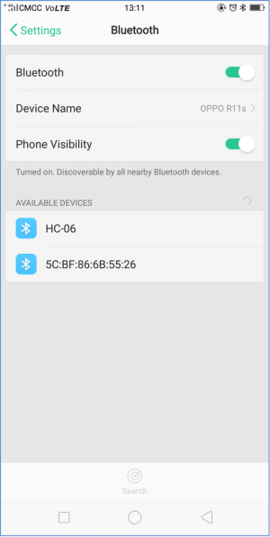
<br>[[Image:KS0193-图片55.png|300px|frameless]]<br> | |||
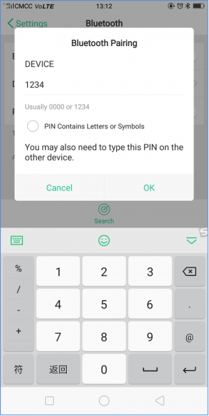
*Tap the HC-06 (search at the first time is a address, so tap the address); the PIN is 1234. | |||
<br>[[Image:KS0193-图片56.png|300px|frameless]]<br> | |||
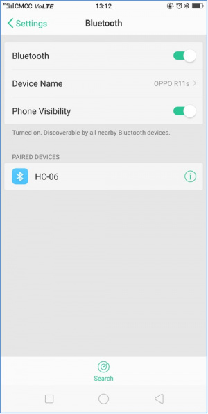
*Finally you will see the paired device. | |||
<br>[[Image:KS0193-图片57-.jpg|300px|frameless]]<br> | |||
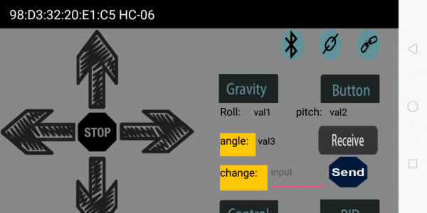
*Connected HC-06 on your phone; now go to tap the Bluetooth connection icon on APP. [[Image:KS0193-图片58.png|50px|frameless]]<br> | |||
<br>[[Image:KS0193-图片59.png|600px|frameless]]<br> | |||
*Then tap the [[Image:KS0193-图片60.png|200px|frameless]] showed on the APP. Up to now, the Bluetooth should connect successfully. <br> | |||
*Bluetooth connected, tap the key [[Image:KS0193-图片61.png|40px|frameless]], the two motors of balance car turn forward;<br> | |||
tap the key [[Image:KS0193-图片62.png|50px|frameless]], the two motors of balance car stop; | |||
tap the key [[Image:KS0193-图片63.png|40px|frameless]], the two motors of balance car turn backward. <br> | |||
<br> | |||
'''Source Code:''' | |||
<pre> | |||
//TB6612 pins | |||
const int right_R1=8; | |||
const int right_R2=12; | |||
const int PWM_R=10; | |||
const int left_L1=7; | |||
const int left_L2=6; | |||
const int PWM_L=9; | |||
char val; // Bluetooth variable | |||
void setup() | |||
{ | |||
Serial.begin(9600); | |||
pinMode(right_R1,OUTPUT); //set TB6612 pins OUTPUT | |||
pinMode(right_R2,OUTPUT); | |||
pinMode(PWM_R,OUTPUT); | |||
pinMode(left_L1,OUTPUT); | |||
pinMode(left_L2,OUTPUT); | |||
pinMode(PWM_L,OUTPUT); | |||
} | |||
void loop() | |||
{ | |||
if(Serial.available()) //if serial buffer value is available | |||
{ | |||
val = Serial.read(); //assign the value read from serial port to val | |||
Serial.println(val); | |||
switch(val) //switch statement | |||
{ | |||
case 'F': front(); break; //motor turns front | |||
case 'B': back(); break; //turn back | |||
case 'S': Stop();break; //stop | |||
} | |||
} | |||
} | |||
//turn front | |||
void front() | |||
{ | |||
digitalWrite(right_R1,HIGH); | |||
digitalWrite(right_R2,LOW); | |||
digitalWrite(left_L1,HIGH); | |||
digitalWrite(left_L2,LOW); | |||
analogWrite(PWM_R,100); | |||
analogWrite(PWM_L,100); | |||
} | |||
//turn back | |||
void back() | |||
{ | |||
digitalWrite(right_R1,LOW); | |||
digitalWrite(right_R2,HIGH); | |||
digitalWrite(left_L1,LOW); | |||
digitalWrite(left_L2,HIGH); | |||
analogWrite(PWM_R,100); | |||
analogWrite(PWM_L,100); | |||
} | |||
//stop | |||
void Stop() | |||
{ | |||
digitalWrite(right_R1,LOW); | |||
digitalWrite(right_R2,HIGH); | |||
digitalWrite(left_L1,LOW); | |||
digitalWrite(left_L2,HIGH); | |||
analogWrite(PWM_R,0); | |||
analogWrite(PWM_L,0); | |||
} | |||
</pre> | |||
<br> | |||
==Project 7: MPU6050 Test== | |||
<br> | |||
'''Description:'''<br> | |||
When DIY the balance car, should obtain its posture at first. The most used is through accelerometer and gyroscope. <br> | |||
In theory, only need two-axis accelerometer (Z-axis in the straight direction and the Y-axis along the moving direction of the car) and a single-axis gyroscope (the angular velocity in the X-axis direction of the car wheel are calculated). <br> | |||
[[File:KS0193-图片64.png|250px|left|thumb]] <br> | |||
In this project, we use the built-in MPU-6050 chip of keyestudio balance shield to test the data of the three-axis accelerometer and the three-axis gyroscope, printing out it on the serial monitor.<br> | |||
The acceleration range is +-2g; the gyroscope range is +-250°/S. <br> | |||
<br> | |||
'''Source Code:''' | |||
<pre> | |||
#include <Wire.h> | |||
long accelX, accelY, accelZ; // set to overall variable; can be used directly inside the function. | |||
float gForceX, gForceY, gForceZ; | |||
long gyroX, gyroY, gyroZ; | |||
float rotX, rotY, rotZ; | |||
void setup() { | |||
Serial.begin(9600); | |||
Wire.begin(); | |||
setupMPU(); | |||
} | |||
void loop() { | |||
recordAccelRegisters(); | |||
recordGyroRegisters(); | |||
printData(); | |||
delay(100); | |||
} | |||
void setupMPU(){ | |||
// REGISTER 0x6B/REGISTER 107:Power Management 1 | |||
Wire.beginTransmission(0b1101000); //This is the I2C address of the MPU (b1101000/b1101001 for AC0 low/high datasheet Sec. 9.2) | |||
Wire.write(0x6B); //Accessing the register 6B/107 - Power Management (Sec. 4.30) | |||
Wire.write(0b00000000); //Setting SLEEP register to 0, using the internal 8 Mhz oscillator | |||
Wire.endTransmission(); | |||
// REGISTER 0x1b/REGISTER 27:Gyroscope Configuration | |||
Wire.beginTransmission(0b1101000); //I2C address of the MPU | |||
Wire.write(0x1B); //Accessing the register 1B - Gyroscope Configuration (Sec. 4.4) | |||
Wire.write(0x00000000); //Setting the gyro to full scale +/- 250deg./s (转化为rpm:250/360 * 60 = 41.67rpm) ;The highest can be converted to 2000deg./s | |||
Wire.endTransmission(); | |||
// REGISTER 0x1C/REGISTER 28:ACCELEROMETER CONFIGURATION | |||
Wire.beginTransmission(0b1101000); //I2C address of the MPU | |||
Wire.write(0x1C); //Accessing the register 1C - Acccelerometer Configuration (Sec. 4.5) | |||
Wire.write(0b00000000); //Setting the accel to +/- 2g(if choose +/- 16g,the value would be 0b00011000) | |||
Wire.endTransmission(); | |||
} | |||
void recordAccelRegisters() { | |||
// REGISTER 0x3B~0x40/REGISTER 59~64 | |||
Wire.beginTransmission(0b1101000); //I2C address of the MPU | |||
Wire.write(0x3B); //Starting register for Accel Readings | |||
Wire.endTransmission(); | |||
Wire.requestFrom(0b1101000,6); //Request Accel Registers (3B - 40) | |||
// Use left shift << and bit operations | Wire.read() read once 1bytes,and automatically read the data of the next address on the next call. | |||
while(Wire.available() < 6); // Waiting for all the 6 bytes data to be sent from the slave machine (Must wait for all data to be stored in the buffer before reading) | |||
accelX = Wire.read()<<8|Wire.read(); //Store first two bytes into accelX (Automatically stored as a defined long value) | |||
accelY = Wire.read()<<8|Wire.read(); //Store middle two bytes into accelY | |||
accelZ = Wire.read()<<8|Wire.read(); //Store last two bytes into accelZ | |||
processAccelData(); | |||
} | |||
void processAccelData(){ | |||
gForceX = accelX / 16384.0; //float = long / float | |||
gForceY = accelY / 16384.0; | |||
gForceZ = accelZ / 16384.0; | |||
} | |||
void recordGyroRegisters() | |||
{ | |||
// REGISTER 0x43~0x48/REGISTER 67~72 | |||
Wire.beginTransmission(0b1101000); //I2C address of the MPU | |||
Wire.write(0x43); //Starting register for Gyro Readings | |||
Wire.endTransmission(); | |||
Wire.requestFrom(0b1101000,6); //Request Gyro Registers (43 ~ 48) | |||
while(Wire.available() < 6); | |||
gyroX = Wire.read()<<8|Wire.read(); //Store first two bytes into accelX | |||
gyroY = Wire.read()<<8|Wire.read(); //Store middle two bytes into accelY | |||
gyroZ = Wire.read()<<8|Wire.read(); //Store last two bytes into accelZ | |||
processGyroData(); | |||
} | |||
void processGyroData() { | |||
rotX = gyroX / 131.0; | |||
rotY = gyroY / 131.0; | |||
rotZ = gyroZ / 131.0; | |||
} | |||
void printData() { | |||
Serial.print("Gyro (deg)"); | |||
Serial.print(" X="); | |||
Serial.print(rotX); | |||
Serial.print(" Y="); | |||
Serial.print(rotY); | |||
Serial.print(" Z="); | |||
Serial.print(rotZ); | |||
Serial.print(" Accel (g)"); | |||
Serial.print(" X="); | |||
Serial.print(gForceX); | |||
Serial.print(" Y="); | |||
Serial.print(gForceY); | |||
Serial.print(" Z="); | |||
Serial.println(gForceZ); | |||
} | |||
</pre> | |||
<br> | |||
'''Test Result:'''<br> | |||
Installed well the balance car, upload the source code and power on; turn the slide switch ON.<br> | |||
Then open the Arduino IDE, set the baud rate to 9600, the serial monitor will pop up the value. <br> | |||
<br>[[File:KS0193-图片65.png|700px|frameless|thumb]] <br> | |||
<br> | |||
== Project 8: Calculating Inclined Angle And Angular Velocity Values == | |||
<br> | |||
'''Description:'''<br> | |||
In the previous project, we have used accelerometer and gyroscope to get the car’s posture. <br> | |||
In this lesson, we use the data measured by MPU-6050 chip to directly get the posture of balance car. <br> | |||
You will learn how to calculate the tilt angle and angular velocity value detected by balance car. Show the test result on the serial monitor. <br> | |||
<br>[[File:KS0193-图片67.png|500px|frameless|thumb]] <br> | |||
<br> | |||
'''Source Code:'''<br> | |||
<span style=color:red > '''Note:'''Before test the source code, do remember to add the corresponding library. </span> <br> | |||
You can refer to the method in the link: | |||
https://wiki.keyestudio.com/How_to_Install_Arduino_Library | |||
<pre> | |||
#include <MPU6050.h> //MPU6050 library | |||
#include <Wire.h> //IIC communication library | |||
MPU6050 mpu6050; //Instantiate an MPU6050 object; name mpu6050 | |||
int16_t ax, ay, az, gx, gy, gz; //Define three-axis acceleration, three-axis gyroscope variables | |||
float Angle; //angle variable | |||
int16_t Gyro_x; //Angular velocity variable | |||
void setup() | |||
{ | |||
// Join the I2C bus | |||
Wire.begin(); //Join the I2C bus sequence | |||
Serial.begin(9600); //open serial monitor and set the baud rate to 9600 | |||
delay(1500); | |||
mpu6050.initialize(); //initialize MPU6050 | |||
delay(2); | |||
} | |||
void loop() | |||
{ | |||
mpu6050.getMotion6(&ax, &ay, &az, &gx, &gy, &gz); //IIC to get MPU6050 six-axis data ax ay az gx gy gz | |||
Angle = -atan2(ay , az) * (180/ PI); //Radial rotation angle calculation formula; the negative sign is direction processing | |||
Gyro_x = -gx / 131; //The X-axis angular velocity calculated by the gyroscope; the negative sign is the direction processing | |||
Serial.print("Angle = "); | |||
Serial.print(Angle); | |||
Serial.print(" Gyro_x = "); | |||
Serial.println(Gyro_x); | |||
} | |||
</pre> | |||
<br> | |||
'''Test Result'''<br> | |||
Installed well the balance car, upload the source code and power on; turn the slide switch ON.<br> | |||
Then open the Arduino IDE, set the baud rate to 9600, the serial monitor will pop up the value. <br> | |||
<br>[[File:KS0193-图片66.png|600px|frameless|thumb]] <br> | |||
<br> | |||
===How to use Kalman filtering to calculate the angel?=== | |||
<br> | |||
'''What’s Kalman filtering ?''' <br> | |||
Kalman filtering is an algorithm that uses the linear system state equation to estimate the state of the system through the input and output of the system. <br> | |||
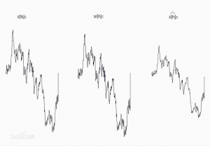
Since the observed data includes the effects of noise and interference in the system, the optimal estimate can also be seen as a filtering process. | |||
[[File:KS0193-图片68.png|300px|right|thumb]] | |||
<br> | |||
Accelerometer data cannot always be trusted 100% due to original data acquired by the MPU6050. <br> | |||
'''Why?''' <br> | |||
The accelerometer measures the inertial force, which may be caused by gravitational force (ideally only gravitational), but it may also be caused by the acceleration (motion) of the device. <br> | |||
<br> | |||
Therefore, even if the accelerometer is in a relatively stable state, it is still very sensitive to vibration and mechanical noise. <br> | |||
That is, the individual number of inclination angles obtained by using the value of the 3-axis acceleration is erroneous, and the error is large. Then you need to use a gyroscope to eliminate any accelerometer errors.<br> | |||
<br> | |||
'''But how is this done? Is there no noise in the gyroscope?''' <br> | |||
The gyroscope is not without noise, but because it measures rotation, it is less sensitive to linear mechanical motion (the type of noise the accelerometer is subjected to). <br> | |||
However, the gyroscope has other types of problems, such as drift (does not return to zero rate values when the rotation stops). <br> | |||
Nonetheless, by averaging the data from the accelerometer and the gyroscope, we can obtain a better estimate than the current device’s tilt angle obtained by using the accelerometer data alone. <br> | |||
Therefore, in order to obtain a smaller, more stable angle, we need to perform Kalman filtering on the inclination angle '''θ''' calculated by the acceleration and the measured angular velocity value '''θ'''' of the gyroscope. <br> | |||
In this project,we use Kalman filter to calculate the balance angle and angular velocity of the balance car, displaying the tested data on the serial monitor. | |||
<br> | |||
<br> | |||
'''Source Code:'''<br> | |||
<span style=color:red> '''Note:''' Before test the source code, do remember to add the corresponding library. </span> <br> | |||
You can refer to the method in the link: | |||
https://wiki.keyestudio.com/How_to_Install_Arduino_Library | |||
<pre> | |||
#include <MPU6050.h> //MPU6050 library | |||
#include <Wire.h> //IIC communication library | |||
MPU6050 mpu6050; //Instantiate an MPU6050 object; name mpu60500 | |||
int16_t ax, ay, az, gx, gy, gz; //Define three-axis acceleration, three-axis gyroscope variables | |||
float Angle; | |||
float Gyro_x,Gyro_y,Gyro_z; //calculate angular velocity of each axis by gyroscope | |||
///////////////////////Kalman_Filter//////////////////////////// | |||
float Q_angle = 0.001; //Covariance of gyroscope noise | |||
float Q_gyro = 0.003; //Covariance of gyroscope drift noise | |||
float R_angle = 0.5; //Covariance of accelerometer | |||
char C_0 = 1; | |||
float dt = 0.005; //The value of dt is the filter sampling time. | |||
float K1 = 0.05; // a function containing the Kalman gain is used to calculate the deviation of the optimal estimate. | |||
float K_0,K_1,t_0,t_1; | |||
float angle_err; | |||
float q_bias; //gyroscope drift | |||
float accelz = 0; | |||
float angle; | |||
float angle_speed; | |||
float Pdot[4] = { 0, 0, 0, 0}; | |||
float P[2][2] = {{ 1, 0 }, { 0, 1 }}; | |||
float PCt_0, PCt_1, E; | |||
//////////////////////Kalman_Filter///////////////////////// | |||
void setup() | |||
{ | |||
// Join the I2C bus | |||
Wire.begin(); //Join the I2C bus sequence | |||
Serial.begin(9600); //open serial monitor and set the baud rate to 9600 | |||
delay(1500); | |||
mpu6050.initialize(); //initialize MPU6050 | |||
delay(2); | |||
} | |||
void loop() | |||
{ | |||
Serial.print("Angle = "); | |||
Serial.print(Angle); | |||
Serial.print(" K_angle = "); | |||
Serial.println(angle); | |||
Serial.print("Gyro_x = "); | |||
Serial.print(Gyro_x); | |||
Serial.print(" K_Gyro_x = "); | |||
Serial.println(angle_speed); | |||
mpu6050.getMotion6(&ax, &ay, &az, &gx, &gy, &gz); //IIC to get MPU6050 six-axis ax ay az gx gy gz | |||
angle_calculate(ax, ay, az, gx, gy, gz, dt, Q_angle, Q_gyro, R_angle, C_0, K1); //obtain angle and KalmanFilter | |||
} | |||
/////////////////////////////angle calculate/////////////////////// | |||
void angle_calculate(int16_t ax,int16_t ay,int16_t az,int16_t gx,int16_t gy,int16_t gz,float dt,float Q_angle,float Q_gyro,float R_angle,float C_0,float K1) | |||
{ | |||
Angle = -atan2(ay , az) * (180/ PI); //Radial rotation angle calculation formula; negative sign is direction processing | |||
Gyro_x = -gx / 131; //The X-axis angular velocity calculated by the gyroscope; the negative sign is the direction processing | |||
Kalman_Filter(Angle, Gyro_x); //KalmanFilter | |||
} | |||
//////////////////////////////////////////////////////////////// | |||
///////////////////////////////KalmanFilter///////////////////// | |||
void Kalman_Filter(double angle_m, double gyro_m) | |||
{ | |||
angle += (gyro_m - q_bias) * dt; //Prior estimate | |||
angle_err = angle_m - angle; | |||
Pdot[0] = Q_angle - P[0][1] - P[1][0]; //Differential of azimuth error covariance | |||
Pdot[1] = - P[1][1]; | |||
Pdot[2] = - P[1][1]; | |||
Pdot[3] = Q_gyro; | |||
P[0][0] += Pdot[0] * dt; //The integral of the covariance differential of the prior estimate error | |||
P[0][1] += Pdot[1] * dt; | |||
P[1][0] += Pdot[2] * dt; | |||
P[1][1] += Pdot[3] * dt; | |||
//Intermediate variable of matrix multiplication | |||
PCt_0 = C_0 * P[0][0]; | |||
PCt_1 = C_0 * P[1][0]; | |||
//Denominator | |||
E = R_angle + C_0 * PCt_0; | |||
//Gain value | |||
K_0 = PCt_0 / E; | |||
K_1 = PCt_1 / E; | |||
t_0 = PCt_0; //Intermediate variable of matrix multiplication | |||
t_1 = C_0 * P[0][1]; | |||
P[0][0] -= K_0 * t_0; //Posterior estimation error covariance | |||
P[0][1] -= K_0 * t_1; | |||
P[1][0] -= K_1 * t_0; | |||
P[1][1] -= K_1 * t_1; | |||
q_bias += K_1 * angle_err; //Posterior estimation | |||
angle_speed = gyro_m - q_bias; //The differential value of the output value; work out the optimal angular velocity | |||
angle += K_0 * angle_err; ////Posterior estimation; work out the optimal angle | |||
} | |||
</pre> | |||
<br> | |||
'''Test Result''' <br> | |||
Installed well the balance car, upload the source code and power on; turn the slide switch ON. <br> | |||
Then open the Arduino IDE, set the baud rate to 9600, the serial monitor will pop up the value. <br> | |||
<br>[[File:KS0193-图片69.png|700px|frameless|thumb]] <br> | |||
<br> | |||
== Project 9: PID Principle == | |||
<br> | |||
'''Description:''' <br> | |||
The '''Proportion''' of deviation, '''Integral''' and the '''Differential''' are linearly combined to form a control quantity, then control object by this control quantity. Such a controller is called a PID controller. <br> | |||
In analog control systems, the most common control law for controllers is PID control. <br> | |||
<span style=color:brown> ''' The block diagram of the common analog PID control system is shown below.''' </span><br> | |||
<br>[[File:KS0193-图片70.png|700px|frameless|thumb]] <br> | |||
<br> | |||
The system consists of an analog PID controller and a controlled object. <br> | |||
In the figure, '''r(t)''' is a given value; '''y(t)''' is the actual output value of the system; <br> | |||
control deviation '''e(t)''' equals the given value subtracts the actual output value. <br> | |||
<span style=color:blue> <big> '''e(t) = r(t) − y(t)''' </big></span><br> | |||
'''e(t)''' is the input of the PID control; '''u(t)''' is used as the output of the PID controller and the input of the controlled object. <br> | |||
So the control law of the analog PID controller is follows: <br> | |||
* '''Kp:''' the proportional coefficient of the controller; <br> | |||
* '''Ti:''' the integral time of the controller, also called the integral coefficient; <br> | |||
* '''Td:''' the differential time of the controller, also called the differential coefficient.<br> | |||
<br> | |||
<span style=color:blue> <big> '''(1) Proportion part ''' </big> </span><br> | |||
The mathematical formula of the proportional part is: <span style=color:blue> <big> ''' Kp×e(t) ''' </big> </span><br> | |||
In the analog PID controller, the proportional link is '''to react to the moment of deviation'''. <br> | |||
<br> | |||
Once the deviation occurs, the controller immediately produces a control action that causes the control amount to change in the direction of decreasing the deviation. <br> | |||
<br> | |||
'''The strength of the control depends on the proportional coefficient Kp'''. <br> | |||
The larger the '''proportional coefficient Kp''', the stronger the control effect, the faster the transition process, the smaller the static deviation of the control process. <br> | |||
<br> | |||
However, the larger the Kp, the more likely it is to oscillate and to destroy the system stability. <br> | |||
Therefore, the selection of the proportional coefficient Kp must be appropriate to achieve a small transition time and a small and stable static difference.<br> | |||
<br> | |||
<span style=color:blue> <big> '''(2) Integral part ''' </big> </span><br> | |||
The mathematical formula of the integral part is: <br> | |||
<br>[[File:KS0193-图片71.png|500px|frameless|thumb]] <br> | |||
From the formula of the integral part, we can know that as long as there is a deviation, its control effect will continue to increase. <br> | |||
<br> | |||
Only when the deviation '''e(t)=0''', its integral can be a constant, and the control effect is not a Increased constant. <br> | |||
It can be seen that '''the integral part can eliminate the deviation of the system'''. <br> | |||
<br> | |||
Although the adjustment function of the integral link will eliminate the static error, it will reduce the response speed of the system and increase the overshoot of the system. <br> | |||
<br> | |||
The larger the '''integral constant Ti''' is, the weaker the accumulation of the integral is. At this time, the system does not oscillate during the transition. <br> | |||
Increasing the integral constant '''Ti''' can slow down the elimination process of the static error, and the time required to eliminate the deviation is also longer; however, can reduce the amount of overshoot and improve the stability of the system. <br> | |||
<br> | |||
When '''Ti''' is small, the integral action is strong; oscillation may occur during the system transition time, but the time required to eliminate the deviation is short. Therefore, '''Ti''' must be determined according to the specific requirements of actual control.<br> | |||
<br> | |||
<span style=color:blue> <big> '''(3) Differential part ''' </big> </span><br> | |||
The mathematical formula of the differential part is: <br> | |||
<br>[[File:KS0193-图片72.png|500px|frameless|thumb]] <br> | |||
In addition to the desire to eliminate static errors, the actual control system requires an accelerated adjustment process. <br> | |||
At the moment when the deviation occurs, or at the moment of the deviation change, not only the immediate response (the role of the proportional link ) is required, but also the appropriate correction is given in advance according to the trend of the deviation. <br> | |||
<br> | |||
In order to achieve this, a differential link can be added to the PI controller to form a PID controller.<br> | |||
<span style=color:orange> '''The role of the differential link is to prevent changes in the deviation.'''</span><br> It is controlled according to the trend of change (speed of change). | |||
The faster the deviation changes, the larger the output of the differential controller, and the correction can be made before the deviation value becomes larger. <br> | |||
<br> | |||
'''The introduction of differential action will help to reduce the overshoot, overcome the oscillation, and stabilize the system, especially for the high-order system, which speeds up the tracking speed of the system.''' <br> | |||
<br> | |||
However, the effect of differentiation is sensitive to the noise of the input signal. <br> | |||
'''For those systems with higher noise, the differential signal is generally not used, or the input signal is filtered before the differential action.'''<br> | |||
<br> | |||
The effect of the differential portion is determined by the '''differential time constant Td''' <br> | |||
The larger the '''Td''', the stronger the effect of suppressing the variation of the deviation '''e(t)'''; <br> | |||
The smaller the '''Td''', the weaker the effect of its resistance to the deviation '''e(t)'''. <br> | |||
The differential part obviously has a great effect on the stability of the system. <br> | |||
By appropriately selecting the differential constant '''Td''', the differential action can be optimized. <br> | |||
<br> | |||
<br> | |||
== Project 10: Upright Loop Adjustment == | |||
<br> | |||
'''Description:''' <br> | |||
In the previous project, we have introduced how to use MPU-6050 chip to calculate the inclined angle and angular velocity value so as to control the car’s balance. <br> | |||
In this section, we will set about to balance the car upright on a horizontal plane via PD ('''proportion''' and '''differential''' ). <br> | |||
However, if placed on a slope or pushed slightly by hand, the car will accelerate in the inclined direction and fall down. <br> | |||
The corresponding inclined angle value can be printed out on the serial monitor. | |||
<br>[[File:KS0193-图片73.png|500px|frameless|thumb]] <br> | |||
<br> | |||
<span style=color:brown> <big>'''Upright balance principle:'''</big> </span><br> | |||
The self-balancing robot stands upright on two coaxial wheels. <br> | |||
The gravity center of robot’s structure design is not on the axis center of the two coaxial wheels and the air flow effect, it will fall in one direction when standing. <br> | |||
To prevent the robot from falling down, it is necessary to add a suitable opposite direction force in the falling direction. <br> | |||
This suitable reverse direction force is provided by a DC geared motor that drives two wheels.<br> | |||
<br> | |||
<big>'''How does a gear DC motor provide a reverse force?'''</big> <br> | |||
The connection between the self-balancing robot body and the wheels is equivalent to a hinge. Figure below is a simplified diagram of a self-balancing robot.<br> | |||
<br>[[File:KS0193-图片74.png|500px|frameless|thumb]] <br> | |||
<br> | |||
If the wheel accelerates to the right, due to the effect of inertia, the center of gravity of the body will be subjected to a leftward '''inertial force F'''. <br> | |||
Just like on the car, if the car accelerates, the person on the car will lean backwards. <br> | |||
<br> | |||
'''But how big is the force in the opposite direction?'''<br> | |||
Now we come to analyze the force of the self-balancing robot body at an oblique angle '''θ'''. <br> | |||
<br>[[File:KS0193-图片75.png|500px|frameless|thumb]] <br> | |||
From the force analysis, we can get the Force balance equation below: | |||
<br>[[File:KS0193-图片76.png|500px|frameless|thumb]] <br> | |||
So can turn into the restoring force of robot: | |||
<br>[[File:KS0193-图片77.png|500px|frameless|thumb]] <br> | |||
From the force balance equation, the reverse direction force is determined by the acceleration '''a''' of the wheel; the magnitude of the acceleration '''a''' is determined by the inclination angle '''θ''' of the robot body. <br> | |||
Thus, if we know the angle of the inclination angle '''θ''', and then control the value of the acceleration '''a''' according to the magnitude of '''θ'''; <br> | |||
It seems that the self-balancing robot will not fall down, that is, a negative feedback control.<br> | |||
<br> | |||
However, it is difficult for the robot to stand upright and stably through simply adjusting the acceleration '''a''' by the inclination angle '''θ'''. <br> | |||
Because the value of '''a''' is difficult to adjust to the exact value, which is often greater than the appropriate value. So the robot tends to the other direction, swing back and fort in the vertical position, with a larger amplitude. <br> | |||
To stabilize the robot return to the vertical position as soon as possible, you need to increase the damping force.<br> | |||
Supposed that the negative feedback control is that the wheel acceleration '''a''' is proportional to the inclination angle '''θ''', and the ratio is '''k1'''. That is: | |||
<br>[[File:KS0193-图片78.png|500px|frameless|thumb]] <br> | |||
Linearize the formula: | |||
<br>[[File:KS0193-图片79.png|400px|frameless|thumb]] <br> | |||
because the inclination angle '''θ''' is relatively small, get: [[File:KS0193-图片80.png|400px|frameless|thumb]] | |||
<br>[[File:KS0193-图片81.png|400px|frameless|thumb]] <br> | |||
The increased damping force is proportional to the speed of the declination; <br> | |||
The factor of proportionality is '''k2''', and the direction is opposite. <br> | |||
Then change the formula into: | |||
<br>[[File:KS0193-图片82.png|500px|frameless|thumb]] <br> | |||
Then can get the final arithmetic of wheel acceleration '''a''': | |||
<br>[[File:KS0193-图片83.png|500px|frameless|thumb]] <br> | |||
<span style=color:brown> '''θ: inclination angle''' ; '''θ': angle speed''' <br> | |||
'''K1; k2: the factor of proportionality.''' </span><br> It is also Kp and Kd in the PD algorithm adjustment of the robot upright balance described later. <br> | |||
Up to now, in theory, the balance robot can be balanced upright.<br> | |||
<br> | |||
'''Source Code:''' | |||
<pre> | |||
#include <MsTimer2.h> //internal timer 2 | |||
#include <PinChangeInt.h> //this library can make all pins of arduino REV4 as external interrupt | |||
#include <MPU6050.h> //MPU6050 library | |||
#include <Wire.h> //IIC communication library | |||
MPU6050 mpu6050; //Instantiate an MPU6050 object; name mpu6050 | |||
int16_t ax, ay, az, gx, gy, gz; //Instantiate an MPU6050 object; name mpu6050 | |||
//TB6612 pins | |||
const int right_R1=8; | |||
const int right_R2=12; | |||
const int PWM_R=10; | |||
const int left_L1=7; | |||
const int left_L2=6; | |||
const int PWM_L=9; | |||
///////////////////////angle parameters////////////////////////////// | |||
float Angle; | |||
float angle_X; //calculate the inclined angle variable of X-axis by accelerometer | |||
float angle_Y; //calculate the inclined angle variable of Y-axis by accelerometer | |||
float angle0 = 1; //Actual measured angle (ideally 0 degrees) | |||
float Gyro_x,Gyro_y,Gyro_z; //Angular angular velocity for gyroscope calculation | |||
///////////////////////angle parameters////////////////////////////// | |||
///////////////////////Kalman_Filter//////////////////////////// | |||
float Q_angle = 0.001; //Covariance of gyroscope noise | |||
float Q_gyro = 0.003; //Covariance of gyroscope drift noise | |||
float R_angle = 0.5; //Covariance of accelerometer | |||
char C_0 = 1; | |||
float dt = 0.005; // The value of dt is the filter sampling time. | |||
float K1 = 0.05; // a function containing the Kalman gain is used to calculate the deviation of the optimal estimate | |||
float K_0,K_1,t_0,t_1; | |||
float angle_err; | |||
float q_bias; //gyroscope drift | |||
float accelz = 0; | |||
float angle; | |||
float angleY_one; | |||
float angle_speed; | |||
float Pdot[4] = { 0, 0, 0, 0}; | |||
float P[2][2] = {{ 1, 0 }, { 0, 1 }}; | |||
float PCt_0, PCt_1, E; | |||
//////////////////////Kalman_Filter///////////////////////// | |||
//////////////////////PD parameters/////////////////////////////// | |||
double kp = 34, ki = 0, kd = 0.62; //Angle loop parameter | |||
double setp0 = 0; //Angle balance point | |||
int PD_pwm; //angle output | |||
float pwm1=0,pwm2=0; | |||
//void anglePWM(); | |||
void setup() | |||
{ | |||
//set the control motor’s pin to OUTPUT | |||
pinMode(right_R1,OUTPUT); | |||
pinMode(right_R2,OUTPUT); | |||
pinMode(left_L1,OUTPUT); | |||
pinMode(left_L2,OUTPUT); | |||
pinMode(PWM_R,OUTPUT); | |||
pinMode(PWM_L,OUTPUT); | |||
//Initial state value | |||
digitalWrite(right_R1,1); | |||
digitalWrite(right_R2,0); | |||
digitalWrite(left_L1,0); | |||
digitalWrite(left_L2,1); | |||
analogWrite(PWM_R,0); | |||
analogWrite(PWM_L,0); | |||
// Join I2C bus | |||
Wire.begin(); //Join the I2C bus sequence | |||
Serial.begin(9600); //open serial monitor, set the baud rate to 9600 | |||
delay(1500); | |||
mpu6050.initialize(); //initialize MPU6050 | |||
delay(2); | |||
//5ms use timer2 to set the timer interrupt (Note: using timer2 will affect the PWM output of pin3 pin11.) | |||
MsTimer2::set(5, DSzhongduan); //5ms execute the function DSzhongduan once | |||
MsTimer2::start(); // start the interrupt | |||
} | |||
void loop() | |||
{ | |||
Serial.print("angle = "); | |||
Serial.println(angle); | |||
Serial.print("Angle = "); | |||
Serial.println(Angle); | |||
/*Serial.print("Gyro_x = "); | |||
Serial.println(Gyro_x); | |||
Serial.print("K_Gyro_x = "); | |||
Serial.println(angle_speed);*/ | |||
//Serial.println(PD_pwm); | |||
//Serial.println(pwm1); | |||
//Serial.println(pwm2); | |||
} | |||
/////////////////////////////////interrupt//////////////////////////// | |||
void DSzhongduan() | |||
{ | |||
sei(); //Allow overall interrupt | |||
mpu6050.getMotion6(&ax, &ay, &az, &gx, &gy, &gz); //IIC to get MPU6050 six-axis data ax ay az gx gy gz | |||
angle_calculate(ax, ay, az, gx, gy, gz, dt, Q_angle, Q_gyro, R_angle, C_0, K1); //get angle and Kalman_Filter | |||
PD(); // angle loop of PD control | |||
anglePWM(); | |||
} | |||
/////////////////////////////////////////////////////////// | |||
/////////////////////////////angle calculation/////////////////////// | |||
void angle_calculate(int16_t ax,int16_t ay,int16_t az,int16_t gx,int16_t gy,int16_t gz,float dt,float Q_angle,float Q_gyro,float R_angle,float C_0,float K1) | |||
{ | |||
Angle = -atan2(ay , az) * (180/ PI); //Radial rotation angle calculation formula; negative sign is direction processing | |||
Gyro_x = -gx / 131; //The X-axis angular velocity calculated by the gyroscope; the negative sign is the direction processing | |||
Kalman_Filter(Angle, Gyro_x); // Kalman Filter | |||
//Rotation Angle Z axis parameter | |||
Gyro_z = -gz / 131; //Z-axis angular velocity | |||
//accelz = az / 16.4; | |||
float angleAx = -atan2(ax, az) * (180 / PI); //Calculate the angle with the x-axis | |||
Gyro_y = -gy / 131.00; //Y-axis angular velocity | |||
Yiorderfilter(angleAx, Gyro_y); //first-order filter | |||
} | |||
//////////////////////////////////////////////////////////////// | |||
///////////////////////////////KalmanFilter///////////////////// | |||
void Kalman_Filter(double angle_m, double gyro_m) | |||
{ | |||
angle += (gyro_m - q_bias) * dt; //Prior estimate | |||
angle_err = angle_m - angle; | |||
Pdot[0] = Q_angle - P[0][1] - P[1][0]; //Differential of azimuth error covariance | |||
Pdot[1] = - P[1][1]; | |||
Pdot[2] = - P[1][1]; | |||
Pdot[3] = Q_gyro; | |||
P[0][0] += Pdot[0] * dt; //A priori estimation error covariance differential integral | |||
P[0][1] += Pdot[1] * dt; | |||
P[1][0] += Pdot[2] * dt; | |||
P[1][1] += Pdot[3] * dt; | |||
//Intermediate variable of matrix multiplication | |||
PCt_0 = C_0 * P[0][0]; | |||
PCt_1 = C_0 * P[1][0]; | |||
//Denominator | |||
E = R_angle + C_0 * PCt_0; | |||
//gain value | |||
K_0 = PCt_0 / E; | |||
K_1 = PCt_1 / E; | |||
t_0 = PCt_0; //Intermediate variable of matrix multiplication | |||
t_1 = C_0 * P[0][1]; | |||
P[0][0] -= K_0 * t_0; //Posterior estimation error covariance | |||
P[0][1] -= K_0 * t_1; | |||
P[1][0] -= K_1 * t_0; | |||
P[1][1] -= K_1 * t_1; | |||
q_bias += K_1 * angle_err; //Posterior estimate | |||
angle_speed = gyro_m - q_bias; //The differential of the output value gives the optimal angular velocity | |||
angle += K_0 * angle_err; ////Posterior estimation to get the optimal angle | |||
} | |||
/////////////////////first-order Filter///////////////// | |||
void Yiorderfilter(float angle_m, float gyro_m) | |||
{ | |||
angleY_one = K1 * angle_m + (1 - K1) * (angleY_one + gyro_m * dt); | |||
} | |||
//////////////////angle PD//////////////////// | |||
void PD() | |||
{ | |||
PD_pwm = kp * (angle + angle0) + kd * angle_speed; //PD angle loop control | |||
} | |||
////////////////////////////PWM end value///////////////////////////// | |||
void anglePWM() | |||
{ | |||
pwm2=-PD_pwm; //The final value assigned to the motor PWM | |||
pwm1=-PD_pwm; | |||
if(pwm1>255) //limit PWM value not greater than 255 | |||
{ | |||
pwm1=255; | |||
} | |||
if(pwm1<-255) | |||
{ | |||
pwm1=-255; | |||
} | |||
if(pwm2>255) | |||
{ | |||
pwm2=255; | |||
} | |||
if(pwm2<-255) | |||
{ | |||
pwm2=-255; | |||
} | |||
if(angle>80 || angle<-80) //When the self-balancing trolley’s tilt angle is greater than 45 degrees, the motor will stop. | |||
{ | |||
pwm1=pwm2=0; | |||
} | |||
if(pwm2>=0) //determine the motor’s steering and speed by the positive and negative of PWM | |||
{ | |||
digitalWrite(left_L1,LOW); | |||
digitalWrite(left_L2,HIGH); | |||
analogWrite(PWM_L,pwm2); | |||
} | |||
else | |||
{ | |||
digitalWrite(left_L1,HIGH); | |||
digitalWrite(left_L2,LOW); | |||
analogWrite(PWM_L,-pwm2); | |||
} | |||
if(pwm1>=0) | |||
{ | |||
digitalWrite(right_R1,LOW); | |||
digitalWrite(right_R2,HIGH); | |||
analogWrite(PWM_R,pwm1); | |||
} | |||
else | |||
{ | |||
digitalWrite(right_R1,HIGH); | |||
digitalWrite(right_R2,LOW); | |||
analogWrite(PWM_R,-pwm1); | |||
} | |||
} | |||
</pre> | |||
<br> | |||
'''Test Result''' <br> | |||
Installed well the balance car, upload the source code and power on; turn the power switch ON.<br> | |||
The balance car will stand upright on the desktop.<br> | |||
Then open the Arduino IDE, set the baud rate to 9600, the serial monitor will pop up the inclined value before filtering and after filtering. | |||
<br>[[File:KS0193-图片84.png|700px|frameless|thumb]] <br> | |||
<br> | |||
== Project 11: Speed Loop Adjustment == | |||
<br> | |||
'''Description:''' <br> | |||
We have introduced before that can adjust the angle to balance the car on the almost horizontal ground by controlling the PD. <br> | |||
However, if subjected to external forces or on a slope, the car can't keep balance because there is an error in speed. So you need to adjust the speed of the car for balancing. <br> | |||
Therefore, a speed measuring module is required. | |||
[[File:KS0193-图片47.png|200px|right|thumb]] | |||
<span style=color:red> The motor we used comes with a Hall encoder for speed measurement. </span> <br> | |||
Based on the previous lesson, add a PI (proportional and integral) control to adjust the speed. In this way, it is possible to control the car to be balanced even if it is on a slope. <br> | |||
The speed loop here is positive feedback, which means that if the car is going backwards, then the car will move forward at a faster speed. <br> | |||
To be specific, if gently push the car with hand, the wheel of the car accelerates in the direction of pushing, that is, the direction in which the car is tilted, so that the tilt angle of the car is reversed in the opposite direction, that is, contrary to the direction of pushing; | |||
the car will accelerate in the direction of tilting, and the speed is accelerated. <br> | |||
The PI adjustment of speed just offsets the previously generated dip angle, and returns to near the initial equilibrium point without falling. <br> | |||
<br> | |||
<span style=color:brown> <big>'''Principle and function of PI regulation:'''</big> </span><br> | |||
<br>[[File:KS0193-图片86.png|500px|frameless|thumb]]; // speed loop control <br> | |||
Adjust the speed with the proportional parameter '''(kp_speed)''', so that the car can quickly approach the required speed; <br> | |||
Adjust the accumulated value of the speed error with the integral parameter '''(ki_speed)''' to eliminate the static error. | |||
<br> | |||
'''For example:''' | |||
[[File:KS0193-图片85.png|150px|right|thumb]] | |||
Supposed that there is a water vat, ensure that the water level in the vat is maintained at a height of 1 meter forever. <br> | |||
Suppose the initial water level is 0.2 meter, then there is an error between the current water level and the target water level, and the error is 0.8m. <br> | |||
At this time, you want to control the water level by adding water.<br> | |||
If simply use the Proportional control algorithm, the amount of water added '''(u)''' is proportional to the error. That is, <span style=color:brown> <big>'''u=kp*error'''</big> </span><br> | |||
<br> | |||
Supposed '''kp=0.5, t=1 (add water in the first time), so u=0.5*0.8=0.4''' , should add the water quantity of 0.4m; now the current water level should be '''0.2m+0.4m=0.6m''' | |||
<br> | |||
Then '''t=2''' (add water in the second time), this time water level 0.6m, error 0.4m, so should add the water quantity '''u=0.5*0.4=0.2''' ; now the current water level should be '''0.6m+0.2m=0.8m''' <br> | |||
Followed by this calculation. The water level will reach 1m. <br> | |||
But there are some shortcomings in such single proportional control, one of which is – '''steady state error'''! <br> | |||
<br> | |||
Like the above example, depending on the value of '''kp''', the system will eventually reach 1 meter without steady state error. <br> | |||
However, considering another situation, suppose that there is water leakage in the process of adding water to the water tank. It is assumed that the water of 0.1 m height will be missed every time the water is added. <br> | |||
<br> | |||
Supposed '''kp=0.5''', after several times of adding water, the water level in the water tank will reach 0.8m, the water level will not change again! Because the water level is 0.8m, the '''error =1-0.8=0.2m'''. <br> | |||
Therefore, the amount of water added to the water tank is '''u=0.5*0.2=0.1m'''. <br> | |||
At the same time, 0.1m of water will flow out from the water tank every time. The added water offsets the leaked water, so the water level will not change! <br> | |||
<br> | |||
In other words, the target water level is 1m, but finally the water system reaches 0.8m and not changes. The system has reached stability. The resulting error is the steady-state error. <br> | |||
Therefore, separate proportional control does not meet the requirements in many cases. So we need integral control algorithm. <br> | |||
<br> | |||
From the above example, you can find that if only use proportional control, may exist the Transient error, so the water level will be only 0.8m. <br> | |||
In control, we introduce a component that is proportional to the integral of the error. <br> | |||
<br> | |||
'''Therefore, the proportional + integral control algorithm is:''' <br> | |||
<span style=color:brown> <big>'''u=kp*error+ ki∗∫error'''</big> </span><br> | |||
<br> | |||
Here we still use the example mentioned above. <br> | |||
The error of the first time is 0.8, and error of the second time is 0.4. At this point, the integral of the error (in the case of discrete, the integral is actually accumulating), '''∫error=0.8+0.4=1.2'''. The amount of control at this time, in addition to a part of proportion, another part is a coefficient '''ki''' multiplied by this integral term. <br> | |||
<br> | |||
Since this integral term will accumulate the previous errors, the steady-state error can be well eliminated. <br> | |||
(assuming that in the case of only proportional terms, the system is stuck in the steady-state error, i.e. 0.8 in the above example. Due to the addition of the integral term, input will increase so that the water level of the tank can be greater than 0.8 and gradually reach the target's 1.0.) <br> | |||
This is the function of integral term. <br> | |||
<br> | |||
'''Source Code:''' | |||
<pre> | |||
#include <MsTimer2.h> //internal timer 2 | |||
#include <PinChangeInt.h> //This library file can make all pins on the REV4 board as external interrupts. | |||
#include <MPU6050.h> //MPU6050 library | |||
#include <Wire.h> //IIC library | |||
MPU6050 mpu6050; //Instantiate an MPU6050 object; name mpu6050 | |||
int16_t ax, ay, az, gx, gy, gz; // Define three-axis acceleration, three-axis gyroscope variables | |||
//TB6612 pins | |||
const int right_R1=8; | |||
const int right_R2=12; | |||
const int PWM_R=10; | |||
const int left_L1=7; | |||
const int left_L2=6; | |||
const int PWM_L=9; | |||
///////////////////////angle parameters////////////////////////////// | |||
float angle_X; //Calculate the tilt angle variable about the X axis from the acceleration | |||
float angle_Y; //Calculate the tilt angle variable about the Y axis from the acceleration | |||
float angle0 = 1; //Actual measured angle (ideally 0 degrees) | |||
float Gyro_x,Gyro_y,Gyro_z; //Angular angular velocity by gyroscope calculation | |||
///////////////////////angle parameters////////////////////////////// | |||
///////////////////////Kalman_Filter//////////////////////////// | |||
float Q_angle = 0.001; //Covariance of gyroscope noise | |||
float Q_gyro = 0.003; //Covariance of gyroscope drift noise | |||
float R_angle = 0.5; //Covariance of accelerometer | |||
char C_0 = 1; | |||
float dt = 0.005; // The value of dt is the filter sampling time. | |||
float K1 = 0.05; //a function containing the Kalman gain is used to calculate the deviation of the optimal estimate | |||
float K_0,K_1,t_0,t_1; | |||
float angle_err; | |||
float q_bias; //Gyro drift | |||
float accelz = 0; | |||
float angle; | |||
float angleY_one; | |||
float angle_speed; | |||
float Pdot[4] = { 0, 0, 0, 0}; | |||
float P[2][2] = {{ 1, 0 }, { 0, 1 }}; | |||
float PCt_0, PCt_1, E; | |||
//////////////////////Kalman_Filter///////////////////////// | |||
//////////////////////PID parameters/////////////////////////////// | |||
double kp = 34, ki = 0, kd = 0.62; //angle loop parameters | |||
double kp_speed = 3.6, ki_speed = 0.080, kd_speed = 0; // speed loop parameters | |||
double setp0 = 0; //angle balance point | |||
int PD_pwm; //angle output | |||
float pwm1=0,pwm2=0; | |||
//////////////////Interrupt speed measurement///////////////////////////// | |||
#define PinA_left 5 //external interrupts | |||
#define PinA_right 4 //external interrupts | |||
volatile long count_right = 0;//Used to calculate the pulse value calculated by the Hall encoder (the volatile long type is to ensure the value is valid) | |||
volatile long count_left = 0; | |||
int speedcc = 0; | |||
//////////////////////pulse calculation///////////////////////// | |||
int lz = 0; | |||
int rz = 0; | |||
int rpluse = 0; | |||
int lpluse = 0; | |||
int pulseright,pulseleft; | |||
////////////////////////////////PI variable parameters////////////////////////// | |||
float speeds_filterold=0; | |||
float positions=0; | |||
int flag1; | |||
double PI_pwm; | |||
int cc; | |||
int speedout; | |||
float speeds_filter; | |||
void setup() | |||
{ | |||
// set the pins of motor to OUTPUT | |||
pinMode(right_R1,OUTPUT); | |||
pinMode(right_R2,OUTPUT); | |||
pinMode(left_L1,OUTPUT); | |||
pinMode(left_L2,OUTPUT); | |||
pinMode(PWM_R,OUTPUT); | |||
pinMode(PWM_L,OUTPUT); | |||
//assign initial state value | |||
digitalWrite(right_R1,1); | |||
digitalWrite(right_R2,0); | |||
digitalWrite(left_L1,0); | |||
digitalWrite(left_L2,1); | |||
analogWrite(PWM_R,0); | |||
analogWrite(PWM_L,0); | |||
pinMode(PinA_left, INPUT); //speed code wheel input | |||
pinMode(PinA_right, INPUT); | |||
// join I2C bus | |||
Wire.begin(); //join I2C bus sequence | |||
Serial.begin(9600); //open the serial monitor to set the baud rate to 9600 | |||
delay(1500); | |||
mpu6050.initialize(); //initialize MPU6050 | |||
delay(2); | |||
//5ms; use timer2 to set timer interruption (note:using timer2 will affect the PWM output of pin3 pin11) | |||
MsTimer2::set(5, DSzhongduan); //5ms ; execute the function DSzhongduan once | |||
MsTimer2::start(); //start interrupt | |||
} | |||
void loop() | |||
{ | |||
Serial.println(angle); | |||
delay(100); | |||
//Serial.println(PD_pwm); | |||
//Serial.println(pwm1); | |||
//Serial.println(pwm2); | |||
//Serial.print("pulseright = "); | |||
//Serial.println(pulseright); | |||
//Serial.print("pulseleft = "); | |||
//Serial.println(pulseleft); | |||
//Serial.println(PI_pwm); | |||
//Serial.println(speeds_filter); | |||
//Serial.println (positions); | |||
//External interrupt for calculating wheel speed | |||
attachPinChangeInterrupt(PinA_left, Code_left, CHANGE); //PinA_left Level change triggers external interrupt; execute subfunction Code_left | |||
attachPinChangeInterrupt(PinA_right, Code_right, CHANGE); //PinA_right Level change triggers external interrupt; execute subfunction Code_right | |||
} | |||
/////////////////////Hall calculation///////////////////////// | |||
//left speed code wheel count | |||
void Code_left() | |||
{ | |||
count_left ++; | |||
} | |||
//Right speed code wheel count | |||
void Code_right() | |||
{ | |||
count_right ++; | |||
} | |||
////////////////////pulse calculation/////////////////////// | |||
void countpluse() | |||
{ | |||
lz = count_left; //Assign the value counted by the code wheel to lz | |||
rz = count_right; | |||
count_left = 0; //Clear the code counter count | |||
count_right = 0; | |||
lpluse = lz; | |||
rpluse = rz; | |||
if ((pwm1 < 0) && (pwm2 < 0)) //judge the moving direction; if backwards(PWM, namely motor voltage is negative), pulse number is a negative number | |||
{ | |||
rpluse = -rpluse; | |||
lpluse = -lpluse; | |||
} | |||
else if ((pwm1 > 0) && (pwm2 > 0)) // if backwards(PWM, namely motor voltage is positive), pulse number is a positive number | |||
{ | |||
rpluse = rpluse; | |||
lpluse = lpluse; | |||
} | |||
else if ((pwm1 < 0) && (pwm2 > 0)) //Judge turning direction of the car; turn left; Right pulse number is a positive number; Left pulse number is a negative number. | |||
{ | |||
rpluse = rpluse; | |||
lpluse = -lpluse; | |||
} | |||
else if ((pwm1 > 0) && (pwm2 < 0)) //Judge turning direction of the car; turn right; Right pulse number is a negative number; Left pulse number is a positive number. | |||
{ | |||
rpluse = -rpluse; | |||
lpluse = lpluse; | |||
} | |||
//enter interrupts per 5ms; pulse number superposes | |||
pulseright += rpluse; | |||
pulseleft += lpluse; | |||
} | |||
/////////////////////////////////interrupts//////////////////////////// | |||
void DSzhongduan() | |||
{ | |||
sei(); //Allow global interrupts | |||
countpluse(); //Pulse superposition subfunction | |||
mpu6050.getMotion6(&ax, &ay, &az, &gx, &gy, &gz); //IIC to get MPU6050 six-axis data ax ay az gx gy gz | |||
angle_calculate(ax, ay, az, gx, gy, gz, dt, Q_angle, Q_gyro, R_angle, C_0, K1); //get angle and Kalman filtering | |||
PD(); //angle loop PD control | |||
anglePWM(); | |||
cc++; | |||
if(cc>=8) //5*8=40,40ms entering once speed PI algorithm | |||
{ | |||
speedpiout(); | |||
cc=0; //Clear | |||
} | |||
} | |||
/////////////////////////////////////////////////////////// | |||
/////////////////////////////angle calculation/////////////////////// | |||
void angle_calculate(int16_t ax,int16_t ay,int16_t az,int16_t gx,int16_t gy,int16_t gz,float dt,float Q_angle,float Q_gyro,float R_angle,float C_0,float K1) | |||
{ | |||
float Angle = -atan2(ay , az) * (180/ PI); //Radial rotation angle calculation formula; negative sign is direction processing | |||
Gyro_x = -gx / 131; //The X-axis angular velocity calculated by the gyroscope; the negative sign is the direction processing | |||
Kalman_Filter(Angle, Gyro_x); //Kalman Filtering | |||
//Rotation angle Z-axis parameter | |||
Gyro_z = -gz / 131; //Z-axis angular velocity | |||
//accelz = az / 16.4; | |||
float angleAx = -atan2(ax, az) * (180 / PI); //Calculate the angle with the x-axis | |||
Gyro_y = -gy / 131.00; //Y-axis angular velocity | |||
Yiorderfilter(angleAx, Gyro_y); //first-order filtering | |||
} | |||
//////////////////////////////////////////////////////////////// | |||
///////////////////////////////KalmanFilter///////////////////// | |||
void Kalman_Filter(double angle_m, double gyro_m) | |||
{ | |||
angle += (gyro_m - q_bias) * dt; //Prior estimate | |||
angle_err = angle_m - angle; | |||
Pdot[0] = Q_angle - P[0][1] - P[1][0]; //Differential of azimuth error covariance | |||
Pdot[1] = - P[1][1]; | |||
Pdot[2] = - P[1][1]; | |||
Pdot[3] = Q_gyro; | |||
P[0][0] += Pdot[0] * dt; //A priori estimation error covariance differential integral | |||
P[0][1] += Pdot[1] * dt; | |||
P[1][0] += Pdot[2] * dt; | |||
P[1][1] += Pdot[3] * dt; | |||
//Intermediate variable of matrix multiplication | |||
PCt_0 = C_0 * P[0][0]; | |||
PCt_1 = C_0 * P[1][0]; | |||
//Denominator | |||
E = R_angle + C_0 * PCt_0; | |||
//gain value | |||
K_0 = PCt_0 / E; | |||
K_1 = PCt_1 / E; | |||
t_0 = PCt_0; //Intermediate variable of matrix multiplication | |||
t_1 = C_0 * P[0][1]; | |||
P[0][0] -= K_0 * t_0; //Posterior estimation error covariance | |||
P[0][1] -= K_0 * t_1; | |||
P[1][0] -= K_1 * t_0; | |||
P[1][1] -= K_1 * t_1; | |||
q_bias += K_1 * angle_err; //Posterior estimate | |||
angle_speed = gyro_m - q_bias; //The differential of the output value gives the optimal angular velocity | |||
angle += K_0 * angle_err; ////Posterior estimation to get the optimal angle | |||
} | |||
/////////////////////first-order filtering///////////////// | |||
void Yiorderfilter(float angle_m, float gyro_m) | |||
{ | |||
angleY_one = K1 * angle_m + (1 - K1) * (angleY_one + gyro_m * dt); | |||
} | |||
//////////////////angle PD//////////////////// | |||
void PD() | |||
{ | |||
PD_pwm = kp * (angle + angle0) + kd * angle_speed; //PD angle loop control | |||
} | |||
//////////////////speed PI//////////////////// | |||
void speedpiout() | |||
{ | |||
float speeds = (pulseleft + pulseright) * 1.0; //Vehicle speed pulse value | |||
pulseright = pulseleft = 0; //Clear | |||
speeds_filterold *= 0.7; //first-order complementary filtering | |||
speeds_filter = speeds_filterold + speeds * 0.3; | |||
speeds_filterold = speeds_filter; | |||
positions += speeds_filter; | |||
positions = constrain(positions, -3550,3550); //Anti-integral saturation | |||
PI_pwm = ki_speed * (setp0 - positions) + kp_speed * (setp0 - speeds_filter); //speed loop control PI | |||
} | |||
//////////////////speed PI//////////////////// | |||
////////////////////////////PWM end value///////////////////////////// | |||
void anglePWM() | |||
{ | |||
pwm2=-PD_pwm - PI_pwm ; //assign the final value of PWM to motor | |||
pwm1=-PD_pwm - PI_pwm ; | |||
if(pwm1>255) //limit PWM value not greater than 255 | |||
{ | |||
pwm1=255; | |||
} | |||
if(pwm1<-255) | |||
{ | |||
pwm1=-255; | |||
} | |||
if(pwm2>255) | |||
{ | |||
pwm2=255; | |||
} | |||
if(pwm2<-255) | |||
{ | |||
pwm2=-255; | |||
} | |||
if(angle>80 || angle<-80) // the inclined angle of balance car is greater than 45°, motor will stop. | |||
{ | |||
pwm1=pwm2=0; | |||
} | |||
if(pwm2>=0) // determine the motor’s steering and speed according to the positive and negative of PWM | |||
{ | |||
digitalWrite(left_L1,LOW); | |||
digitalWrite(left_L2,HIGH); | |||
analogWrite(PWM_L,pwm2); | |||
} | |||
else | |||
{ | |||
digitalWrite(left_L1,HIGH); | |||
digitalWrite(left_L2,LOW); | |||
analogWrite(PWM_L,-pwm2); | |||
} | |||
if(pwm1>=0) | |||
{ | |||
digitalWrite(right_R1,LOW); | |||
digitalWrite(right_R2,HIGH); | |||
analogWrite(PWM_R,pwm1); | |||
} | |||
else | |||
{ | |||
digitalWrite(right_R1,HIGH); | |||
digitalWrite(right_R2,LOW); | |||
analogWrite(PWM_R,-pwm1); | |||
} | |||
} | |||
</pre> | |||
<br> | |||
'''Test Result'''<br> | |||
Installed well the balance car, upload the source code and power on; turn the power switch ON.<br> | |||
The balance car will stand upright on the desktop. <br> | |||
Then open the Arduino IDE, set the baud rate to 9600, the serial monitor will pop up the inclined value of balance car. | |||
<br>[[File:KS0193-图片87.png|700px|frameless|thumb]]<br> | |||
<br> | |||
Remove the USB cable and balance the car upright on the ground. <br> | |||
If you push it gently by hand, the car will advance in the direction you push, but the tilt angle of the car is opposite to the direction of the push, so the car will return to the balance point without falling. <br> | |||
<br> | |||
== Project 12: Steering Loop Control == | |||
<br> | |||
'''Description:''' <br> | |||
The steering of the car also needs to be adjusted by the PD.<br> | |||
The balance robot is driven by the left and right motor speed difference to eliminate the deviation from the center of the road. <br> | |||
By adjusting the direction of the balancing robot and adding the balancing robot to the forward motion, the distance difference between the balancing robot and the center line can be gradually eliminated. <br> | |||
This process is a proportional P process, so the differential control of balance robot generally only needs simple proportional control to complete the direction control.<br> | |||
However, since the robot car itself is equipped with a relatively heavy object such as a battery, it has a large moment of inertia. It may occurs steering overshoot phenomenon during the adjustment process. If it is not suppressed, the balance robot will oversteer and fall down. | |||
According to the experience of angle and speed control mentioned above, in order to eliminate the overshoot in the direction control of balance robot, it is necessary to increase the angle differential D control. | |||
<br>[[File:KS0193-图片1.png|500px|frameless|thumb]]<br> | |||
<br> | |||
== Project 13: Bluetooth Control == | |||
<br> | |||
'''Description:''' <br> | |||
In the above projects, you have learned how to balance the robot upright; how to use the Bluetooth APP to control the balancing robot. <br> | |||
In this project, let’s move on to combine these two functions. To begin with, control the balance robot stand upright; then make the robot move in different directions using Android Bluetooth control. <br> | |||
[[File:KS0193-图片88.png|150px|right|thumb]] | |||
However, due to the errors caused by the installation and the mpu6050, there may be a phenomenon that go fast and easily fall down or slow to turn back or can’t move. The solution please refer to the project 12 and the second section mentioned below. <br> | |||
<br> | |||
<span style=color:brown> '''Notice:''' <br> | |||
The balance shield comes with a slide switch for Bluetooth communication. When upload the code for testing, must turn the switch OFF; or else, uploading fails. <br> | |||
When connect to Bluetooth module, should turn the switch ON. </span><br> | |||
<br> | |||
'''Source Code:''' <br> | |||
<span style=color:red> '''Note:''' Before test the source code, do remember to add the corresponding library. </span><br> | |||
You can refer to the method in the link: | |||
https://wiki.keyestudio.com/How_to_Install_Arduino_Library | |||
<br> | |||
<pre> | |||
#include <MsTimer2.h> //internal timer 2 | |||
#include <PinChangeInt.h> //this library can make all pins of arduino REV4 as external interrupt | |||
#include <MPU6050.h> //MPU6050 library | |||
#include <Wire.h> //IIC communication library | |||
MPU6050 mpu6050; //Instantiate an MPU6050 object; name mpu6050 | |||
int16_t ax, ay, az, gx, gy, gz; //Define three-axis acceleration, three-axis gyroscope variables | |||
//TB6612 pins | |||
const int right_R1=8; | |||
const int right_R2=12; | |||
const int PWM_R=10; | |||
const int left_L1=7; | |||
const int left_L2=6; | |||
const int PWM_L=9; | |||
///////////////////////angle parameters////////////////////////////// | |||
float angle_X; //calculate the inclined angle variable of X-axis by accelerometer | |||
float angle_Y; //calculate the inclined angle variable of Y-axis by accelerometer | |||
float angle0 = 1; //Actual measured angle (ideally 0 degrees) | |||
float Gyro_x,Gyro_y,Gyro_z; //Angular angular velocity for gyroscope calculation | |||
///////////////////////angle parameters////////////////////////////// | |||
///////////////////////Kalman_Filter//////////////////////////// | |||
float Q_angle = 0.001; //Covariance of gyroscope noise | |||
float Q_gyro = 0.003; //Covariance of gyroscope drift noise | |||
float R_angle = 0.5; //Covariance of accelerometer | |||
char C_0 = 1; | |||
float dt = 0.005; //The value of dt is the filter sampling time | |||
float K1 = 0.05; // a function containing the Kalman gain; used to calculate the deviation of the optimal estimate | |||
float K_0,K_1,t_0,t_1; | |||
float angle_err; | |||
float q_bias; //gyroscope drift | |||
float accelz = 0; | |||
float angle; | |||
float angleY_one; | |||
float angle_speed; | |||
float Pdot[4] = { 0, 0, 0, 0}; | |||
float P[2][2] = {{ 1, 0 }, { 0, 1 }}; | |||
float PCt_0, PCt_1, E; | |||
//////////////////////Kalman_Filter///////////////////////// | |||
//////////////////////PID parameters/////////////////////////////// | |||
double kp = 34, ki = 0, kd = 0.62; //angle loop parameters | |||
double kp_speed = 3.6, ki_speed = 0.080, kd_speed = 0; // speed loop parameters | |||
double kp_turn = 24, ki_turn = 0, kd_turn = 0.08; // steering loop parameters | |||
double setp0 = 0; //Angle balance point | |||
int PD_pwm; //angle output | |||
float pwm1=0,pwm2=0; | |||
//////////////////Interrupt speed count///////////////////////////// | |||
#define PinA_left 5 //external interrupt | |||
#define PinA_right 4 //external interrupt | |||
volatile long count_right = 0;//Used to calculate the pulse value calculated by the Hall encoder (the volatile long type is to ensure the value is valid) | |||
volatile long count_left = 0; | |||
int speedcc = 0; | |||
//////////////////////pulse count///////////////////////// | |||
int lz = 0; | |||
int rz = 0; | |||
int rpluse = 0; | |||
int lpluse = 0; | |||
int pulseright,pulseleft; | |||
////////////////////////////////PI variable parameter////////////////////////// | |||
float speeds_filterold=0; | |||
float positions=0; | |||
int flag1; | |||
double PI_pwm; | |||
int cc; | |||
int speedout; | |||
float speeds_filter; | |||
//////////////////////////////steering PD/////////////////// | |||
int turnmax,turnmin,turnout; | |||
float Turn_pwm = 0; | |||
int zz=0; | |||
int turncc=0; | |||
//Bluetooth// | |||
int front = 0;//go front variable | |||
int back = 0;//go back variable | |||
int left = 0;//turn left | |||
int right = 0;//turn right | |||
char val; | |||
void setup() | |||
{ | |||
//set the motor control pins to OUTPUT | |||
pinMode(right_R1,OUTPUT); | |||
pinMode(right_R2,OUTPUT); | |||
pinMode(left_L1,OUTPUT); | |||
pinMode(left_L2,OUTPUT); | |||
pinMode(PWM_R,OUTPUT); | |||
pinMode(PWM_L,OUTPUT); | |||
//assign initial state value | |||
digitalWrite(right_R1,1); | |||
digitalWrite(right_R2,0); | |||
digitalWrite(left_L1,0); | |||
digitalWrite(left_L2,1); | |||
analogWrite(PWM_R,0); | |||
analogWrite(PWM_L,0); | |||
pinMode(PinA_left, INPUT); //Speed encoder input | |||
pinMode(PinA_right, INPUT); | |||
// join I2C bus | |||
Wire.begin(); //join I2C bus sequence | |||
Serial.begin(9600); //open the serial monitor and set the baud rate to 9600 | |||
delay(1500); | |||
mpu6050.initialize(); //initialize MPU6050 | |||
delay(2); | |||
//5ms; use timer2 to set timer interruption (note:using timer2 will affect the PWM output of pin3 pin11) | |||
MsTimer2::set(5, DSzhongduan); //5ms ; execute the function DSzhongduan once | |||
MsTimer2::start(); //start interrupt | |||
} | |||
void loop() | |||
{ | |||
Serial.print(angle_speed); | |||
Serial.print(" "); | |||
Serial.println(Gyro_x); | |||
//Serial.println(angle); | |||
//delay(100); | |||
//Serial.println(PD_pwm); | |||
//Serial.println(pwm1); | |||
//Serial.println(pwm2); | |||
//Serial.print("pulseright = "); | |||
//Serial.println(pulseright); | |||
//Serial.print("pulseleft = "); | |||
//Serial.println(pulseleft); | |||
//Serial.println(PI_pwm); | |||
//Serial.println(speeds_filter); | |||
//Serial.println (positions); | |||
//Serial.println(Turn_pwm); | |||
//Serial.println(Gyro_z); | |||
//Serial.println(Turn_pwm); | |||
if(Serial.available()) | |||
{ | |||
val = Serial.read(); //assign the value read from serial port to val | |||
//Serial.println(val); | |||
switch(val) //switch statement | |||
{ | |||
case 'F': front=250; break; //if val equals to F,front=250,balance robot goes front. | |||
case 'B': back=-250; break; //go back | |||
case 'L': left=1; break; //turn left | |||
case 'R': right=1; break; // turn right | |||
case 'S': front=0,back=0,left=0,right=0;break; //stop | |||
case 'D': Serial.print(angle);break; //when receiving ‘D’,send value of angle to APP | |||
} | |||
} | |||
//external interrupt; used to calculate the wheel speed | |||
attachPinChangeInterrupt(PinA_left, Code_left, CHANGE); //PinA_left Level change triggers external interrupt; execute subfunction Code_left | |||
attachPinChangeInterrupt(PinA_right, Code_right, CHANGE); //PinA_right Level change triggers external interrupt; execute subfunction Code_right | |||
} | |||
/////////////////////Hall count///////////////////////// | |||
//left speed encoder count | |||
void Code_left() | |||
{ | |||
count_left ++; | |||
} | |||
//right speed encoder count | |||
void Code_right() | |||
{ | |||
count_right ++; | |||
} | |||
////////////////////pulse count/////////////////////// | |||
void countpluse() | |||
{ | |||
lz = count_left; //assign the value counted by encoder to lz | |||
rz = count_right; | |||
count_left = 0; //clear the count quantity | |||
count_right = 0; | |||
lpluse = lz; | |||
rpluse = rz; | |||
if ((pwm1 < 0) && (pwm2 < 0)) //judge the moving direction of balance robot; if go back (PWM the motor voltage is negative), the number of pulses is negative. | |||
{ | |||
rpluse = -rpluse; | |||
lpluse = -lpluse; | |||
} | |||
else if ((pwm1 > 0) && (pwm2 > 0)) // if go back (PWM the motor voltage is positive) , the number of pulses is positive. | |||
{ | |||
rpluse = rpluse; | |||
lpluse = lpluse; | |||
} | |||
else if ((pwm1 < 0) && (pwm2 > 0)) //judge the moving direction of balance robot; if turn left, right pulse is positive but left pulse is negative. | |||
{ | |||
rpluse = rpluse; | |||
lpluse = -lpluse; | |||
} | |||
else if ((pwm1 > 0) && (pwm2 < 0)) //judge the moving direction of balance robot; if turn right , right pulse is negative but left pulse is positive. | |||
{ | |||
rpluse = -rpluse; | |||
lpluse = lpluse; | |||
} | |||
//entering interrupt per 5ms,pulse will plus | |||
pulseright += rpluse; | |||
pulseleft += lpluse; | |||
} | |||
/////////////////////////////////interrupt //////////////////////////// | |||
void DSzhongduan() | |||
{ | |||
sei(); //allow overall interrupt | |||
countpluse(); //pulse count subfunction | |||
mpu6050.getMotion6(&ax, &ay, &az, &gx, &gy, &gz); //IIC to get MPU6050 six-axis data ax ay az gx gy gz | |||
angle_calculate(ax, ay, az, gx, gy, gz, dt, Q_angle, Q_gyro, R_angle, C_0, K1); //get the angle and Kalman filtering | |||
PD(); //PD control of angle loop | |||
anglePWM(); | |||
cc++; | |||
if(cc>=8) //5*8=40,40ms entering PI count of speed once | |||
{ | |||
speedpiout(); | |||
cc=0; // Clear | |||
} | |||
turncc++; | |||
if(turncc>4) //20ms entering PI count of steering once | |||
{ | |||
turnspin(); | |||
turncc=0; //Clear | |||
} | |||
} | |||
/////////////////////////////////////////////////////////// | |||
/////////////////////////////tilt angle calculation/////////////////////// | |||
void angle_calculate(int16_t ax,int16_t ay,int16_t az,int16_t gx,int16_t gy,int16_t gz,float dt,float Q_angle,float Q_gyro,float R_angle,float C_0,float K1) | |||
{ | |||
float Angle = -atan2(ay , az) * (180/ PI); //Radial rotation angle calculation formula; the negative sign is direction processing. | |||
Gyro_x = -gx / 131; //The X-axis angular velocity calculated by the gyroscope ; the negative sign is the direction processing. | |||
Kalman_Filter(Angle, Gyro_x); // Kalman Filter | |||
// Z-axis angular velocity | |||
Gyro_z = -gz / 131; //speed of Z-axis | |||
//accelz = az / 16.4; | |||
float angleAx = -atan2(ax, az) * (180 / PI); //calculate the included angle of X-axis | |||
Gyro_y = -gy / 131.00; //angle speed of Y-axis | |||
Yiorderfilter(angleAx, Gyro_y); //first-order filtering | |||
} | |||
//////////////////////////////////////////////////////////////// | |||
///////////////////////////////KalmanFilter///////////////////// | |||
void Kalman_Filter(double angle_m, double gyro_m) | |||
{ | |||
angle += (gyro_m - q_bias) * dt; //prior estimate | |||
angle_err = angle_m - angle; | |||
Pdot[0] = Q_angle - P[0][1] - P[1][0]; //The differential of the covariance of the prior estimate error | |||
Pdot[1] = - P[1][1]; | |||
Pdot[2] = - P[1][1]; | |||
Pdot[3] = Q_gyro; | |||
P[0][0] += Pdot[0] * dt; //The integral of the covariance differential of the prior estimate error | |||
P[0][1] += Pdot[1] * dt; | |||
P[1][0] += Pdot[2] * dt; | |||
P[1][1] += Pdot[3] * dt; | |||
//Intermediate variables in matrix multiplication | |||
PCt_0 = C_0 * P[0][0]; | |||
PCt_1 = C_0 * P[1][0]; | |||
//denominator | |||
E = R_angle + C_0 * PCt_0; | |||
//gain value | |||
K_0 = PCt_0 / E; | |||
K_1 = PCt_1 / E; | |||
t_0 = PCt_0; //Intermediate variables in matrix multiplication | |||
t_1 = C_0 * P[0][1]; | |||
P[0][0] -= K_0 * t_0; //the covariance of the prior estimate error | |||
P[0][1] -= K_0 * t_1; | |||
P[1][0] -= K_1 * t_0; | |||
P[1][1] -= K_1 * t_1; | |||
q_bias += K_1 * angle_err; //posterior estimate | |||
angle_speed = gyro_m - q_bias; //The differential of the output value; get the optimal angular velocity | |||
angle += K_0 * angle_err; ////posterior estimate; get the optimal angular velocity | |||
} | |||
/////////////////////first-order filtering///////////////// | |||
void Yiorderfilter(float angle_m, float gyro_m) | |||
{ | |||
angleY_one = K1 * angle_m + (1 - K1) * (angleY_one + gyro_m * dt); | |||
} | |||
//////////////////angle PD//////////////////// | |||
void PD() | |||
{ | |||
PD_pwm = kp * (angle + angle0) + kd * angle_speed; //PD angle loop control | |||
} | |||
//////////////////speed PI//////////////////// | |||
void speedpiout() | |||
{ | |||
float speeds = (pulseleft + pulseright) * 1.0; //pulse value of speed | |||
pulseright = pulseleft = 0; //Clear | |||
speeds_filterold *= 0.7; //first-order complementary filtering | |||
speeds_filter = speeds_filterold + speeds * 0.3; | |||
speeds_filterold = speeds_filter; | |||
positions += speeds_filter; | |||
positions += front; //Forward control fusion | |||
positions += back; //backward control fusion | |||
positions = constrain(positions, -3550,3550); //Anti-integral saturation | |||
PI_pwm = ki_speed * (setp0 - positions) + kp_speed * (setp0 - speeds_filter); //speed loop controlling PI | |||
} | |||
//////////////////speed PI//////////////////// | |||
///////////////////////////steering///////////////////////////////// | |||
void turnspin() | |||
{ | |||
int flag = 0; // | |||
float turnspeed = 0; | |||
float rotationratio = 0; | |||
if (left == 1 || right == 1) | |||
{ | |||
if (flag == 0) //judge the speed before turning; increase the car’s flexibility. | |||
{ | |||
turnspeed = ( pulseright + pulseleft); //current speed of car; pulse expression | |||
flag=1; | |||
} | |||
if (turnspeed < 0) //Absolute value of the car's current speed | |||
{ | |||
turnspeed = -turnspeed; | |||
} | |||
if(left==1||right==1) //if press left key or right key | |||
{ | |||
turnmax=3; //maximum value of turning | |||
turnmin=-3; // minimum value of turning | |||
} | |||
rotationratio = 5 / turnspeed; //set the value by speed | |||
if (rotationratio < 0.5) | |||
{ | |||
rotationratio = 0.5; | |||
} | |||
if (rotationratio > 5) | |||
{ | |||
rotationratio = 5; | |||
} | |||
} | |||
else | |||
{ | |||
rotationratio = 0.5; | |||
flag = 0; | |||
turnspeed = 0; | |||
} | |||
if (left ==1)//plus by direction parameter | |||
{ | |||
turnout += rotationratio; | |||
} | |||
else if (right == 1 )//plus by direction parameter | |||
{ | |||
turnout -= rotationratio; | |||
} | |||
else turnout = 0; | |||
if (turnout > turnmax) turnout = turnmax;//the max value setting of amplitude | |||
if (turnout < turnmin) turnout = turnmin;//the min value setting of amplitude | |||
Turn_pwm = -turnout * kp_turn - Gyro_z * kd_turn;//The rotation PD algorithm controls the fusion speed and Z axis rotation positioning | |||
} | |||
///////////////////////////turning///////////////////////////////// | |||
////////////////////////////PWM end value///////////////////////////// | |||
void anglePWM() | |||
{ | |||
pwm2=-PD_pwm - PI_pwm + Turn_pwm; //assign the end value of PWM to motor | |||
pwm1=-PD_pwm - PI_pwm - Turn_pwm; | |||
if(pwm1>255) //limit the PWM value not more than 255 | |||
{ | |||
pwm1=255; | |||
} | |||
if(pwm1<-255) | |||
{ | |||
pwm1=-255; | |||
} | |||
if(pwm2>255) | |||
{ | |||
pwm2=255; | |||
} | |||
if(pwm2<-255) | |||
{ | |||
pwm2=-255; | |||
} | |||
if(angle>80 || angle<-80) //if tilt angle is greater than 45° , motor will stop. | |||
{ | |||
pwm1=pwm2=0; | |||
} | |||
if(pwm2>=0) //motor’s turning and speed are determined by the positive or negative of PWM | |||
{ | |||
digitalWrite(left_L1,LOW); | |||
digitalWrite(left_L2,HIGH); | |||
analogWrite(PWM_L,pwm2); | |||
} | |||
else | |||
{ | |||
digitalWrite(left_L1,HIGH); | |||
digitalWrite(left_L2,LOW); | |||
analogWrite(PWM_L,-pwm2); | |||
} | |||
if(pwm1>=0) | |||
{ | |||
digitalWrite(right_R1,LOW); | |||
digitalWrite(right_R2,HIGH); | |||
analogWrite(PWM_R,pwm1); | |||
} | |||
else | |||
{ | |||
digitalWrite(right_R1,HIGH); | |||
digitalWrite(right_R2,LOW); | |||
analogWrite(PWM_R,-pwm1); | |||
} | |||
} | |||
</pre> | |||
<br> | |||
'''Use Method:''' <br> | |||
* 1)installed well the balance robot, upload the test code; <br> | |||
* 2)pull out the USB cable, then turn the power control switch of shield ON. <br> | |||
* 3)the balance shield comes with a Bluetooth switch; then turn the switch ON. <br> | |||
Refer to the project 6 on how to connect the Bluetooth module. <br> | |||
* 4)Open the APP to connect Bluetooth; if Bluetooth connected, place the balance robot on the ground to make it stand upright. <br> | |||
Then tap the Button key [[File:KS0193-图片89.png|50px|frameless|thumb]], you can control the robot go front, back, turn left or turn right by tapping the direction arrow icon. <br> | |||
<br>[[File:KS0193-图片90.png|700px|frameless|thumb]]<br> | |||
* 5)press the key [[File:KS0193-图片91.png|50px|frameless|thumb]] ,you can also control the robot moving by gravity sensing system( must carried by your phone). | |||
<br> | |||
=== Adjusting Balance Angle and PID by Bluetooth APP === | |||
<br> | |||
'''Description:'''<br> | |||
In the previous projects, we were able to control the car's upright balance and movement. <br> | |||
However, due to the error caused by the car installation and the mpu6050, the mechanical balance angle of the car is not perpendicular to the horizontal plane. <br> | |||
Thus when using Bluetooth controls the car’s forward or backward, its tilt angle is small and the wheel is almost motionless or moves slowly. <br> | |||
When controlling the car’s backward or forward, its tilt angle is very large and the wheel speed is very fast, so it is likely to accelerate over a certain distance and fall down. <br> | |||
In order to reduce these errors, we can adjust the mechanical balance angle and the main parameters of the PID through the mobile APP. | |||
[[File:KS0193-图片92.png|500px|right|thumb]] | |||
<br> | |||
<span style=color:brown><big>'''How to use the Bluetooth APP?'''</big> </span><br> | |||
<br> | |||
1) follow the method mentioned before to upload the code to control the balance car move.<br> | |||
2) set the tilt angle. When controlling the balance car, the front and rear speed of the car are not the same, so there is a deviation. | |||
Then click the key [[File:KS0193-图片100.png|50px|frameless|thumb]], get a tilt angle. Shown below. <br> | |||
<br>[[File:KS0193-图片93.png|700px|frameless|thumb]] <br> | |||
<br> | |||
If get a negative number, type a positive number on the change bar[[File:KS0193-图片94.png|50px|frameless|thumb]], so that the negative number plus the positive number equals to nearly 0. <br> | |||
Then click the key [[File:KS0193-图片95.png|50px|frameless|thumb]], control the balance car move and observe the moving state.<br> | |||
<br> | |||
3) You can also press the PID [[File:KS0193-图片96.png|50px|frameless|thumb]] on the Bluetooth APP,to set the PID parameters,then tap other keys to adjust the PID parameters, making the balance robot stable.<br> | |||
Or refer to the moving state of balance car under different parameters. | |||
<br>[[File:KS0193-图片97.png|700px|frameless|thumb]]<br> | |||
<br> | |||
Settings finished, press the key[[File:KS0193-图片98.png|50px|frameless|thumb]] to return to the control interface. <br> | |||
<br> | |||
'''Source Code:''' <br> | |||
<span style=color:red>'''Note:''' Before test the source code, do remember to add the corresponding library. </span> <br> | |||
You can refer to the method in the link: | |||
https://wiki.keyestudio.com/How_to_Install_Arduino_Library | |||
<pre> | |||
#include <MsTimer2.h> //internal timer 2 | |||
#include <PinChangeInt.h> //this library can make all pins of arduino REV4 as external interrupt | |||
#include <MPU6050.h> //MPU6050 library | |||
#include <Wire.h> //IIC communication library | |||
MPU6050 mpu6050; //Instantiate an MPU6050 object; name mpu6050 | |||
int16_t ax, ay, az, gx, gy, gz; //Define three-axis acceleration, three-axis gyroscope variables | |||
//TB6612 pins | |||
const int right_R1=8; | |||
const int right_R2=12; | |||
const int PWM_R=10; | |||
const int left_L1=7; | |||
const int left_L2=6; | |||
const int PWM_L=9; | |||
///////////////////////angle parameters////////////////////////////// | |||
float angle_X; //calculate the inclined angle variable of X-axis by accelerometer | |||
float angle_Y; //calculate the inclined angle variable of Y-axis by accelerometer | |||
int angle0 = 0; //Actual measured angle (ideally 0 degrees) | |||
float Gyro_x,Gyro_y,Gyro_z; //Angular angular velocity for gyroscope calculation | |||
///////////////////////angle parameters////////////////////////////// | |||
///////////////////////Kalman_Filter//////////////////////////// | |||
float Q_angle = 0.001; //Covariance of gyroscope noise | |||
float Q_gyro = 0.003; //Covariance of gyroscope drift noise | |||
float R_angle = 0.5; //Covariance of accelerometer | |||
char C_0 = 1; | |||
float dt = 0.005; //The value of dt is the filter sampling time | |||
float K1 = 0.05; // a function containing the Kalman gain; used to calculate the deviation of the optimal estimate | |||
float K_0,K_1,t_0,t_1; | |||
float angle_err; | |||
float q_bias; //gyroscope drift | |||
float accelz = 0; | |||
float angle; | |||
float angleY_one; | |||
float angle_speed; | |||
float Pdot[4] = { 0, 0, 0, 0}; | |||
float P[2][2] = {{ 1, 0 }, { 0, 1 }}; | |||
float PCt_0, PCt_1, E; | |||
//////////////////////Kalman_Filter///////////////////////// | |||
//////////////////////PID parameters/////////////////////////////// | |||
double kp = 34.00, ki = 0, kd = 0.62; //angle loop parameter | |||
double kp_speed = 3.60, ki_speed = 0.08, kd_speed = 0; // speed loop parameter | |||
double kp_turn = 24.00, ki_turn = 0, kd_turn = 0.08; // steering loop parameter | |||
double setp0 = 0; //angle balance point | |||
int PD_pwm; //angle output | |||
float pwm1=0,pwm2=0; | |||
//////////////////interrupt speed count///////////////////////////// | |||
#define PinA_left 5 //external interrupt | |||
#define PinA_right 4 //external interrupt | |||
volatile long count_right = 0;//Used to calculate the pulse value calculated by the Hall encoder (the volatile long type is to ensure that the value is valid) | |||
volatile long count_left = 0; | |||
int speedcc = 0; | |||
//////////////////////pulse count///////////////////////// | |||
int lz = 0; | |||
int rz = 0; | |||
int rpluse = 0; | |||
int lpluse = 0; | |||
int pulseright,pulseleft; | |||
////////////////////////////////PI variable parameter////////////////////////// | |||
float speeds_filterold=0; | |||
float positions=0; | |||
int flag1; | |||
double PI_pwm; | |||
int cc; | |||
int speedout; | |||
float speeds_filter; | |||
//////////////////////////////steering PD/////////////////// | |||
int turnmax,turnmin,turnout; | |||
float Turn_pwm = 0; | |||
int zz=0; | |||
int turncc=0; | |||
//Bluetooth// | |||
int front = 0;//backward variable | |||
int back = 0;//forward variable | |||
int left = 0;//turn left | |||
int right = 0;//turn right | |||
char val; | |||
int TT; | |||
void setup() | |||
{ | |||
//set the control pins of motor to OUTPUT | |||
pinMode(right_R1,OUTPUT); | |||
pinMode(right_R2,OUTPUT); | |||
pinMode(left_L1,OUTPUT); | |||
pinMode(left_L2,OUTPUT); | |||
pinMode(PWM_R,OUTPUT); | |||
pinMode(PWM_L,OUTPUT); | |||
//assign the initial value | |||
digitalWrite(right_R1,1); | |||
digitalWrite(right_R2,0); | |||
digitalWrite(left_L1,0); | |||
digitalWrite(left_L2,1); | |||
analogWrite(PWM_R,0); | |||
analogWrite(PWM_L,0); | |||
pinMode(PinA_left, INPUT); //speed encoder input | |||
pinMode(PinA_right, INPUT); | |||
// join I2C bus | |||
Wire.begin(); //join I2C bus sequence | |||
Serial.begin(9600); //open the serial monitor, set the baud rate to 9600 | |||
delay(1500); | |||
mpu6050.initialize(); //initialize MPU6050 | |||
delay(2); | |||
//5ms; use timer2 to set timer interruption (note:using timer2 will affect the PWM output of pin3 pin11) | |||
MsTimer2::set(5, DSzhongduan); //5ms; execute the function DSzhongduan once | |||
MsTimer2::start(); //start interrupt | |||
} | |||
void loop() | |||
{ | |||
//Serial.println(angle); | |||
//delay(100); | |||
//Serial.println(PD_pwm); | |||
//Serial.println(pwm1); | |||
//Serial.println(pwm2); | |||
//Serial.print("pulseright = "); | |||
//Serial.println(pulseright); | |||
//Serial.print("pulseleft = "); | |||
//Serial.println(pulseleft); | |||
//Serial.println(PI_pwm); | |||
//Serial.println(speeds_filter); | |||
//Serial.println (positions); | |||
//Serial.println(Turn_pwm); | |||
//Serial.println(Gyro_z); | |||
//Serial.println(Turn_pwm); | |||
if(Serial.available()) | |||
{ | |||
val = Serial.read(); //assign the value read from serial port to val | |||
//Serial.println(val); | |||
switch(val) //switch statement | |||
{ | |||
case 'F': front=250; break; //if vale equals F,front=250,go front | |||
case 'B': back=-250; break; //go back | |||
case 'L': left=1; break; //turn left | |||
case 'R': right=1; break; //turn right | |||
case 'S': front=0,back=0,left=0,right=0;break; //stop | |||
case 'Q': Serial.print(angle);break; //receiving‘D’,send the value of variable angle to APP | |||
case 'P': kp=kp+0.5,Serial.print(kp);break; | |||
case 'O': kp=kp-0.5,Serial.print(kp);break; | |||
case 'I': kd=kd+0.02,Serial.print(kd);break; | |||
case 'U': kd=kd-0.02,Serial.print(kd);break; | |||
case 'Y': kp_speed=kp_speed+0.05,Serial.print(kp_speed);break; | |||
case 'T': kp_speed=kp_speed-0.05,Serial.print(kp_speed);break; | |||
case 'G': ki_speed=ki_speed+0.01,Serial.print(ki_speed);break; | |||
case 'H': ki_speed=ki_speed-0.01,Serial.print(ki_speed);break; | |||
case 'J': kp_turn=kp_turn+0.4,Serial.print(kp_turn);break; | |||
case 'K': kp_turn=kp_turn-0.4,Serial.print(kp_turn);break; | |||
case 'N': kd_turn=kd_turn+0.01,Serial.print(kd_turn);break; | |||
case 'M': kd_turn=kd_turn-0.01,Serial.print(kd_turn);break; | |||
} | |||
if(val=='F'||val=='B'||val=='L'||val=='R'||val=='S'||val=='Q'||val=='P'||val=='O'||val=='I'||val=='U'||val=='Y'||val=='T'||val=='G'||val=='H'||val=='J'||val=='K'||val=='N'||val=='M') | |||
{ | |||
TT = angle0; | |||
} | |||
else | |||
{ | |||
TT = val; | |||
angle0=TT; | |||
} | |||
//Serial.println(angle0); | |||
} | |||
//external interrupt; used to calculate the wheel speed | |||
attachPinChangeInterrupt(PinA_left, Code_left, CHANGE); //PinA_left Level change triggers external interrupt; execute subfunction Code_left | |||
attachPinChangeInterrupt(PinA_right, Code_right, CHANGE); //PinA_right Level change triggers external interrupt; execute Code_right | |||
} | |||
/////////////////////Hall count///////////////////////// | |||
//left speed encoder count | |||
void Code_left() | |||
{ | |||
count_left ++; | |||
} | |||
//right speed encoder count | |||
void Code_right() | |||
{ | |||
count_right ++; | |||
} | |||
////////////////////pulse count/////////////////////// | |||
void countpluse() | |||
{ | |||
lz = count_left; //assign the value counted by encoder to lz | |||
rz = count_right; | |||
count_left = 0; //Clear the count quantity | |||
count_right = 0; | |||
lpluse = lz; | |||
rpluse = rz; | |||
if ((pwm1 < 0) && (pwm2 < 0)) //judge the car’s moving direction; if backward (PWM /motor voltage is negative), pulse is a negative number. | |||
{ | |||
rpluse = -rpluse; | |||
lpluse = -lpluse; | |||
} | |||
else if ((pwm1 > 0) && (pwm2 > 0)) //if backward (PWM /motor voltage is positive), pulse is a positive number. | |||
{ | |||
rpluse = rpluse; | |||
lpluse = lpluse; | |||
} | |||
else if ((pwm1 < 0) && (pwm2 > 0)) //judge the car’s moving direction; if turn left, the right pulse is positive; left pulse is negative. | |||
{ | |||
rpluse = rpluse; | |||
lpluse = -lpluse; | |||
} | |||
else if ((pwm1 > 0) && (pwm2 < 0)) //judge the car’s moving direction; if turn right, the right pulse is negative ; left pulse is positive. | |||
{ | |||
rpluse = -rpluse; | |||
lpluse = lpluse; | |||
} | |||
//entering interrupt per,pulse plus | |||
pulseright += rpluse; | |||
pulseleft += lpluse; | |||
} | |||
/////////////////////////////////interrupt//////////////////////////// | |||
void DSzhongduan() | |||
{ | |||
sei(); //allow overall interrupt | |||
countpluse(); //pulse plus subfunction | |||
mpu6050.getMotion6(&ax, &ay, &az, &gx, &gy, &gz); //IIC to get MPU6050 six-axis data ax ay az gx gy gz | |||
angle_calculate(ax, ay, az, gx, gy, gz, dt, Q_angle, Q_gyro, R_angle, C_0, K1); //get angle and Kalman filtering | |||
PD(); // PD control of angle loop | |||
anglePWM(); | |||
cc++; | |||
if(cc>=8) //5*8=40,that is, execute the PI calculation of speed once per 40ms | |||
{ | |||
speedpiout(); | |||
cc=0; //Clear | |||
} | |||
turncc++; | |||
if(turncc>4) //20ms, that is, execute the PD calculation of steering once per 40ms | |||
{ | |||
turnspin(); | |||
turncc=0; //Clear | |||
} | |||
} | |||
/////////////////////////////////////////////////////////// | |||
/////////////////////////////tilt angle calculation /////////////////////// | |||
void angle_calculate(int16_t ax,int16_t ay,int16_t az,int16_t gx,int16_t gy,int16_t gz,float dt,float Q_angle,float Q_gyro,float R_angle,float C_0,float K1) | |||
{ | |||
float Angle = -atan2(ay , az) * (180/ PI); //Radial rotation angle calculation formula ; negative sign is direction processing | |||
Gyro_x = -gx / 131; //The X-axis angular velocity calculated by the gyroscope ; the negative sign is the direction processing | |||
Kalman_Filter(Angle, Gyro_x); //Kalman Filter | |||
//Rotation angle Z-axis parameter | |||
Gyro_z = -gz / 131; //angle speed of Z-axis | |||
//accelz = az / 16.4; | |||
float angleAx = -atan2(ax, az) * (180 / PI); //calculate the inclined angle of X-axis | |||
Gyro_y = -gy / 131.00; //angle speed of Y-axis | |||
Yiorderfilter(angleAx, Gyro_y); //first-order filtering | |||
} | |||
//////////////////////////////////////////////////////////////// | |||
///////////////////////////////KalmanFilter///////////////////// | |||
void Kalman_Filter(double angle_m, double gyro_m) | |||
{ | |||
angle += (gyro_m - q_bias) * dt; //prior estimate | |||
angle_err = angle_m - angle; | |||
Pdot[0] = Q_angle - P[0][1] - P[1][0]; //The differential of the covariance of the prior estimate error | |||
Pdot[1] = - P[1][1]; | |||
Pdot[2] = - P[1][1]; | |||
Pdot[3] = Q_gyro; | |||
P[0][0] += Pdot[0] * dt; //A priori estimation error covariance differential integral | |||
P[0][1] += Pdot[1] * dt; | |||
P[1][0] += Pdot[2] * dt; | |||
P[1][1] += Pdot[3] * dt; | |||
//Intermediate variables in matrix multiplication | |||
PCt_0 = C_0 * P[0][0]; | |||
PCt_1 = C_0 * P[1][0]; | |||
//denominator | |||
E = R_angle + C_0 * PCt_0; | |||
//gain value | |||
K_0 = PCt_0 / E; | |||
K_1 = PCt_1 / E; | |||
t_0 = PCt_0; //Intermediate variables in matrix multiplication | |||
t_1 = C_0 * P[0][1]; | |||
P[0][0] -= K_0 * t_0; //Posterior estimation error covariance | |||
P[0][1] -= K_0 * t_1; | |||
P[1][0] -= K_1 * t_0; | |||
P[1][1] -= K_1 * t_1; | |||
q_bias += K_1 * angle_err; //Posterior estimate | |||
angle_speed = gyro_m - q_bias; //The differential of the output value; get the optimal angular velocity | |||
angle += K_0 * angle_err; ////Posterior estimation; get the optimal angle | |||
} | |||
/////////////////////first-order filtering///////////////// | |||
void Yiorderfilter(float angle_m, float gyro_m) | |||
{ | |||
angleY_one = K1 * angle_m + (1 - K1) * (angleY_one + gyro_m * dt); | |||
} | |||
//////////////////angle PD//////////////////// | |||
void PD() | |||
{ | |||
PD_pwm = kp * (angle + angle0) + kd * angle_speed; //PD angle loop control | |||
} | |||
//////////////////speed PI//////////////////// | |||
void speedpiout() | |||
{ | |||
float speeds = (pulseleft + pulseright) * 1.0; //speed; pulse value | |||
pulseright = pulseleft = 0; //Clear | |||
speeds_filterold *= 0.7; //first-order complementary filtering | |||
speeds_filter = speeds_filterold + speeds * 0.3; | |||
speeds_filterold = speeds_filter; | |||
positions += speeds_filter; | |||
positions += front; //Forward control fusion | |||
positions += back; //Backward control fusion | |||
positions = constrain(positions, -3550,3550); //Anti-integral saturation | |||
PI_pwm = ki_speed * (setp0 - positions) + kp_speed * (setp0 - speeds_filter); //speed loop control PI | |||
} | |||
//////////////////speed PI//////////////////// | |||
///////////////////////////turning///////////////////////////////// | |||
void turnspin() | |||
{ | |||
int flag = 0; // | |||
float turnspeed = 0; | |||
float rotationratio = 0; | |||
if (left == 1 || right == 1) | |||
{ | |||
if (flag == 0) //judge the current speed before turning, to increase the flexibility. | |||
{ | |||
turnspeed = ( pulseright + pulseleft); //current speed; pulse expression | |||
flag=1; | |||
} | |||
if (turnspeed < 0) //absolute value of current speed | |||
{ | |||
turnspeed = -turnspeed; | |||
} | |||
if(left==1||right==1) //if press the left key or right key | |||
{ | |||
turnmax=5; //the maximum value of turning | |||
turnmin=-5; //the minimum value of turning | |||
} | |||
rotationratio = 5 / turnspeed; //set by the speed of car | |||
if (rotationratio < 0.5) | |||
{ | |||
rotationratio = 0.5; | |||
} | |||
if (rotationratio > 5) | |||
{ | |||
rotationratio = 5; | |||
} | |||
} | |||
else | |||
{ | |||
rotationratio = 0.5; | |||
flag = 0; | |||
turnspeed = 0; | |||
} | |||
if (left ==1)//add according to orientation parameter | |||
{ | |||
turnout += rotationratio; | |||
} | |||
else if (right == 1 )//add according to orientation parameter | |||
{ | |||
turnout -= rotationratio; | |||
} | |||
else turnout = 0; | |||
if (turnout > turnmax) turnout = turnmax;//the max value setting of amplitude | |||
if (turnout < turnmin) turnout = turnmin;//the min value setting of amplitude | |||
Turn_pwm = -turnout * kp_turn - Gyro_z * kd_turn;//The rotation PD algorithm controls the fusion speed and Z axis rotation positioning | |||
} | |||
///////////////////////////steering///////////////////////////////// | |||
////////////////////////////PWM end value///////////////////////////// | |||
void anglePWM() | |||
{ | |||
pwm2=-PD_pwm - PI_pwm + Turn_pwm; //assign the end value of PWM to motor | |||
pwm1=-PD_pwm - PI_pwm - Turn_pwm; | |||
if(pwm1>255) //limit PWM value not more than 255 | |||
{ | |||
pwm1=255; | |||
} | |||
if(pwm1<-255) | |||
{ | |||
pwm1=-255; | |||
} | |||
if(pwm2>255) | |||
{ | |||
pwm2=255; | |||
} | |||
if(pwm2<-255) | |||
{ | |||
pwm2=-255; | |||
} | |||
if(angle>80 || angle<-80) // if the tilt angle is greater than 45°,motor will stop turning. | |||
{ | |||
pwm1=pwm2=0; | |||
} | |||
if(pwm2>=0) //determine the motor’s turning and speed by the negative and positive of PWM | |||
{ | |||
digitalWrite(left_L1,LOW); | |||
digitalWrite(left_L2,HIGH); | |||
analogWrite(PWM_L,pwm2); | |||
} | |||
else | |||
{ | |||
digitalWrite(left_L1,HIGH); | |||
digitalWrite(left_L2,LOW); | |||
analogWrite(PWM_L,-pwm2); | |||
} | |||
if(pwm1>=0) | |||
{ | |||
digitalWrite(right_R1,LOW); | |||
digitalWrite(right_R2,HIGH); | |||
analogWrite(PWM_R,pwm1); | |||
} | |||
else | |||
{ | |||
digitalWrite(right_R1,HIGH); | |||
digitalWrite(right_R2,LOW); | |||
analogWrite(PWM_R,-pwm1); | |||
} | |||
} | |||
</pre> | |||
<br>[[File:KS0193-图片99.png|600px|frameless|thumb]]<br> | |||
<br> | |||
== Project 14: Adjusting Balance Angle and Bluetooth Control == | |||
<br> | |||
'''Description:''' <br> | |||
In the above project, we first connect the Bluetooth and then adjust the balancing angle of car on the Bluetooth APP. <br> | |||
Now, we first adjust the balancing angle of car by hand; then connect the Android Bluetooth to control the car moving via Bluetooth APP. <br> | |||
<span style=color:red>'''Notice:''' | |||
* 1)Thew balance shield comes with a slide switch for Bluetooth communication. When upload the code for testing, must turn the switch OFF; or else, uploading fails. <br> | |||
When connect to Bluetooth module, should turn the switch ON. <br> | |||
* 2)Using the source code of this project, can only adjust once each time starting up; must adjust the angle first, or else the car can’t keep balance. </span><br> | |||
<br> | |||
'''Source Code:''' <br> | |||
<span style=color:red> '''Note:'''Before test the source code, do remember to add the corresponding library. </span><br> | |||
You can refer to the method in the link: | |||
https://wiki.keyestudio.com/How_to_Install_Arduino_Library | |||
<pre> | |||
#include <MsTimer2.h> //Internal timer2 | |||
#include <PinChangeInt.h> //This library file can make all pins on the REV4 board as external interrupts. Define three-axis acceleration, three-axis gyroscope variables | |||
#include <MPU6050.h> //MPU6050 Library | |||
#include <Wire.h> //IIC communication library | |||
MPU6050 mpu6050; // Instantiate an MPU6050 object; name mpu6050 | |||
int16_t ax, ay, az, gx, gy, gz; //Define three-axis acceleration, three-axis gyroscope variables | |||
//TB6612 pins definition | |||
const int right_R1=8; | |||
const int right_R2=12; | |||
const int PWM_R=10; | |||
const int left_L1=7; | |||
const int left_L2=6; | |||
const int PWM_L=9; | |||
const int buz = 11; | |||
const int btn = 13; | |||
///////////////////////angle parameters////////////////////////////// | |||
float angle_X; // calculate the inclined angle variable of X-axis by accelerometer | |||
float angle_Y; //calculate the inclined angle variable of Y-axis by accelerometer | |||
float angle0 = 0; //mechanical balance angle (ideally 0 degrees) | |||
float Gyro_x,Gyro_y,Gyro_z; //Angular angular velocity by gyroscope calculation | |||
///////////////////////angle parameter////////////////////////////// | |||
///////////////////////Kalman_Filter//////////////////////////// | |||
float Q_angle = 0.001; //Covariance of gyroscope noise | |||
float Q_gyro = 0.003; // Covariance of gyroscope drift noise | |||
float R_angle = 0.5; //Covariance of accelerometer | |||
char C_0 = 1; | |||
float dt = 0.005; //The value of dt is the filter sampling time | |||
float K1 = 0.05; // a function containing the Kalman gain is used to calculate the deviation of the optimal estimate | |||
float K_0,K_1,t_0,t_1; | |||
float angle_err; | |||
float q_bias; //gyroscope drift | |||
float accelz = 0; | |||
float angle; | |||
float angleY_one; | |||
float angle_speed; | |||
float Pdot[4] = { 0, 0, 0, 0}; | |||
float P[2][2] = {{ 1, 0 }, { 0, 1 }}; | |||
float PCt_0, PCt_1, E; | |||
//////////////////////Kalman_Filter///////////////////////// | |||
//////////////////////PID parameter/////////////////////////////// | |||
double kp = 34, ki = 0, kd = 0.62; //angle loop parameter | |||
double kp_speed = 3.56, ki_speed = 0.072, kd_speed = 0; // speed loop parameter | |||
double kp_turn = 24, ki_turn = 0, kd_turn = 0.08; // steering loop parameter | |||
double setp0 = 0; //angle balance point | |||
int PD_pwm; //angle output | |||
float pwm1=0,pwm2=0; | |||
//////////////////interrupt speed count///////////////////////////// | |||
#define PinA_left 5 //external interrupt | |||
#define PinA_right 4 //external interrupt | |||
volatile long count_right = 0;//Used to calculate the pulse value calculated by the Hall encoder (the volatile long type is to ensure the value is valid) | |||
volatile long count_left = 0; | |||
int speedcc = 0; | |||
//////////////////////pulse count///////////////////////// | |||
int lz = 0; | |||
int rz = 0; | |||
int rpluse = 0; | |||
int lpluse = 0; | |||
int pulseright,pulseleft; | |||
////////////////////////////////PI variable parameter////////////////////////// | |||
float speeds_filterold=0; | |||
float positions=0; | |||
int flag1; | |||
double PI_pwm; | |||
int cc; | |||
int speedout; | |||
float speeds_filter; | |||
//////////////////////////////turning PD/////////////////// | |||
int turnmax,turnmin,turnout; | |||
float Turn_pwm = 0; | |||
int zz=0; | |||
int turncc=0; | |||
//Bluetooth// | |||
int front = 0;//forward variable | |||
int back = 0;//backward | |||
int left = 0;//turn left | |||
int right = 0;//turn right | |||
char val; | |||
int i,button; | |||
void setup() | |||
{ | |||
//set the motor control pins to OUTPUT | |||
pinMode(right_R1,OUTPUT); | |||
pinMode(right_R2,OUTPUT); | |||
pinMode(left_L1,OUTPUT); | |||
pinMode(left_L2,OUTPUT); | |||
pinMode(PWM_R,OUTPUT); | |||
pinMode(PWM_L,OUTPUT); | |||
//assign the initial state value | |||
digitalWrite(right_R1,1); | |||
digitalWrite(right_R2,0); | |||
digitalWrite(left_L1,0); | |||
digitalWrite(left_L2,1); | |||
analogWrite(PWM_R,0); | |||
analogWrite(PWM_L,0); | |||
pinMode(PinA_left, INPUT); //speed encoder input | |||
pinMode(PinA_right, INPUT); | |||
pinMode(btn,INPUT); | |||
pinMode(buz,OUTPUT); | |||
// join I2C bus | |||
Wire.begin(); //join I2C bus sequence | |||
Serial.begin(9600); //open the serial monitor and set the baud rate to 9600 | |||
delay(1500); | |||
mpu6050.initialize(); //initialize MPU6050 | |||
delay(2); | |||
//5ms; use timer2 to set the timer interrupt (note: using timer2 may affects the PWM output of pin3 pin11) | |||
MsTimer2::set(5, DSzhongduan); //5ms; execute the function DSzhongduan once | |||
MsTimer2::start(); //start interrupt | |||
} | |||
//buzzer | |||
void buzzer() | |||
{ | |||
for(int i=0;i<50;i++) | |||
{ | |||
digitalWrite(buz,HIGH); | |||
delay(1); | |||
digitalWrite(buz,LOW); | |||
delay(1); | |||
} | |||
delay(50); | |||
for(int i=0;i<50;i++) | |||
{ | |||
digitalWrite(buz,HIGH); | |||
delay(1); | |||
digitalWrite(buz,LOW); | |||
delay(1); | |||
} | |||
} | |||
void loop() | |||
{ | |||
//Serial.println(angle0); | |||
//Serial.print("angle= "); | |||
//Serial.println(angle); | |||
//delay(1); | |||
//Serial.println(PD_pwm); | |||
//Serial.println(pwm1); | |||
//Serial.println(pwm2); | |||
//Serial.print("pulseright = "); | |||
//Serial.println(pulseright); | |||
//Serial.print("pulseleft = "); | |||
//Serial.println(pulseleft); | |||
//Serial.println(PI_pwm); | |||
//Serial.println(speeds_filter); | |||
//Serial.println (positions); | |||
//Serial.println(Turn_pwm); | |||
//Serial.println(Gyro_z); | |||
//Serial.println(Turn_pwm); | |||
while(i<1) | |||
{ | |||
button = digitalRead(btn); | |||
if(button == 0) | |||
{ | |||
angle0=-angle; | |||
//Serial.println(angle0); | |||
buzzer(); | |||
i++; | |||
} | |||
} | |||
if(Serial.available()) | |||
{ | |||
val = Serial.read(); //assign the value read from the serial port to val | |||
//Serial.println(val); | |||
switch(val) //switch statement | |||
{ | |||
case 'F': front=250; break; //if val equals F,front=250,car will move forward | |||
case 'B': back=-250; break; //go back | |||
case 'L': left=1; break; //turn left | |||
case 'R': right=1; break; //turn right | |||
case 'S': front=0,back=0,left=0,right=0;break; //stop | |||
case 'D': Serial.print(angle);break; | |||
} | |||
} | |||
//external interrupt; used to calculate the wheel speed | |||
attachPinChangeInterrupt(PinA_left, Code_left, CHANGE); //PinA_left Level change triggers the external interrupt; execute the subfunction Code_left | |||
attachPinChangeInterrupt(PinA_right, Code_right, CHANGE); //PinA_right Level change triggers the external interrupt; execute the subfunction Code_right | |||
} | |||
/////////////////////Hall count///////////////////////// | |||
//left speed encoder count | |||
void Code_left() | |||
{ | |||
count_left ++; | |||
} | |||
//right speed encoder count | |||
void Code_right() | |||
{ | |||
count_right ++; | |||
} | |||
////////////////////pulse count/////////////////////// | |||
void countpluse() | |||
{ | |||
lz = count_left; //assign the value counted by encoder to lz | |||
rz = count_right; | |||
count_left = 0; //Clear count quantity | |||
count_right = 0; | |||
lpluse = lz; | |||
rpluse = rz; | |||
if ((pwm1 < 0) && (pwm2 < 0)) //judge the car’s moving direction; if backward (PWM namely motor voltage is negative), pulse is a negative number. | |||
{ | |||
rpluse = -rpluse; | |||
lpluse = -lpluse; | |||
} | |||
else if ((pwm1 > 0) && (pwm2 > 0)) //if backward (PWM namely motor voltage is positive), pulse is a positive number. | |||
{ | |||
rpluse = rpluse; | |||
lpluse = lpluse; | |||
} | |||
else if ((pwm1 < 0) && (pwm2 > 0)) //judge the car’s moving direction; if turn left, right pulse is a positive number; left pulse is a negative number. | |||
{ | |||
rpluse = rpluse; | |||
lpluse = -lpluse; | |||
} | |||
else if ((pwm1 > 0) && (pwm2 < 0)) //judge the car’s moving direction; if turn right, right pulse is a negative number; left pulse is a positive number. | |||
{ | |||
rpluse = -rpluse; | |||
lpluse = lpluse; | |||
} | |||
// enter interrupt per 5ms,pulse number plus | |||
pulseright += rpluse; | |||
pulseleft += lpluse; | |||
} | |||
/////////////////////////////////interrupt //////////////////////////// | |||
void DSzhongduan() | |||
{ | |||
sei(); //allow overall interrupt | |||
countpluse(); //pulse plus subfunction | |||
mpu6050.getMotion6(&ax, &ay, &az, &gx, &gy, &gz); //IIC to get MPU6050 six-axis data ax ay az gx gy gz | |||
angle_calculate(ax, ay, az, gx, gy, gz, dt, Q_angle, Q_gyro, R_angle, C_0, K1); //get angle and Kalmam filtering | |||
PD(); //angle loop PD control | |||
anglePWM(); | |||
cc++; | |||
if(cc>=8) //5*8=40,enter PI algorithm of speed per 40ms | |||
{ | |||
speedpiout(); | |||
cc=0; //Clear | |||
} | |||
turncc++; | |||
if(turncc>4) //20ms; enter PD algorithm of steering | |||
{ | |||
turnspin(); | |||
turncc=0; //Clear | |||
} | |||
} | |||
/////////////////////////////////////////////////////////// | |||
/////////////////////////////tilt calculation/////////////////////// | |||
void angle_calculate(int16_t ax,int16_t ay,int16_t az,int16_t gx,int16_t gy,int16_t gz,float dt,float Q_angle,float Q_gyro,float R_angle,float C_0,float K1) | |||
{ | |||
float Angle = -atan2(ay , az) * (180/ PI); //Radial rotation angle calculation formula ; negative sign is direction processing | |||
Gyro_x = -gx / 131; //The X-axis angular velocity calculated by the gyroscope; the negative sign is the direction processing | |||
Kalman_Filter(Angle, Gyro_x); //Kalman Filter | |||
//rotating angle Z-axis parameter | |||
Gyro_z = -gz / 131; //angle speed of Z-axis | |||
//accelz = az / 1604; | |||
float angleAx = -atan2(ax, az) * (180 / PI); //calculate the inclined angle with x-axis | |||
Gyro_y = -gy / 131.00; //angle speed of Y-axis | |||
Yiorderfilter(angleAx, Gyro_y); //first-order filtering | |||
} | |||
//////////////////////////////////////////////////////////////// | |||
///////////////////////////////KalmanFilter///////////////////// | |||
void Kalman_Filter(double angle_m, double gyro_m) | |||
{ | |||
angle += (gyro_m - q_bias) * dt; //prior estimate | |||
angle_err = angle_m - angle; | |||
Pdot[0] = Q_angle - P[0][1] - P[1][0]; //The differential of the covariance of the prior estimate error | |||
Pdot[1] = - P[1][1]; | |||
Pdot[2] = - P[1][1]; | |||
Pdot[3] = Q_gyro; | |||
P[0][0] += Pdot[0] * dt; //The integral of the covariance differential of the prior estimate error | |||
P[0][1] += Pdot[1] * dt; | |||
P[1][0] += Pdot[2] * dt; | |||
P[1][1] += Pdot[3] * dt; | |||
//Intermediate variables in matrix multiplication | |||
PCt_0 = C_0 * P[0][0]; | |||
PCt_1 = C_0 * P[1][0]; | |||
//denominator | |||
E = R_angle + C_0 * PCt_0; | |||
//gain value | |||
K_0 = PCt_0 / E; | |||
K_1 = PCt_1 / E; | |||
t_0 = PCt_0; //Intermediate variables in matrix multiplication | |||
t_1 = C_0 * P[0][1]; | |||
P[0][0] -= K_0 * t_0; //Posterior estimation error covariance | |||
P[0][1] -= K_0 * t_1; | |||
P[1][0] -= K_1 * t_0; | |||
P[1][1] -= K_1 * t_1; | |||
q_bias += K_1 * angle_err; //Posterior estimate | |||
angle_speed = gyro_m - q_bias; //The differential of the output value gives the optimal angular velocity | |||
angle += K_0 * angle_err; ////Posterior estimation; get the optimal angle | |||
} | |||
/////////////////////first-order filter///////////////// | |||
void Yiorderfilter(float angle_m, float gyro_m) | |||
{ | |||
angleY_one = K1 * angle_m + (1 - K1) * (angleY_one + gyro_m * dt); | |||
} | |||
//////////////////angle PD//////////////////// | |||
void PD() | |||
{ | |||
PD_pwm = kp * (angle + angle0) + kd * angle_speed; //PD angle loop control | |||
} | |||
//////////////////speed PI//////////////////// | |||
void speedpiout() | |||
{ | |||
float speeds = (pulseleft + pulseright) * 1.0; //speed pulse value | |||
pulseright = pulseleft = 0; //clear | |||
speeds_filterold *= 0.7; //first-order complementary filtering | |||
speeds_filter = speeds_filterold + speeds * 0.3; | |||
speeds_filterold = speeds_filter; | |||
positions += speeds_filter; | |||
positions += front; //Forward control fusion | |||
positions += back; //backward control fusion | |||
positions = constrain(positions, -3550,3550); //Anti-integral saturation | |||
PI_pwm = ki_speed * (setp0 - positions) + kp_speed * (setp0 - speeds_filter); //speed loop control PI | |||
} | |||
//////////////////speed PI//////////////////// | |||
///////////////////////////turning///////////////////////////////// | |||
void turnspin() | |||
{ | |||
int flag = 0; // | |||
float turnspeed = 0; | |||
float rotationratio = 0; | |||
if (left == 1 || right == 1) | |||
{ | |||
if (flag == 0) //judge the speed before rotate, to increase the flexibility | |||
{ | |||
turnspeed = ( pulseright + pulseleft); //current speed ; express in pulse | |||
flag=1; | |||
} | |||
if (turnspeed < 0) //speed absolute value | |||
{ | |||
turnspeed = -turnspeed; | |||
} | |||
if(left==1||right==1) //if press left key or right key | |||
{ | |||
turnmax=3; //max turning value | |||
turnmin=-3; //min turning value | |||
} | |||
rotationratio = 5 / turnspeed; //speed setting value | |||
if (rotationratio < 0.5) | |||
{ | |||
rotationratio = 0.5; | |||
} | |||
if (rotationratio > 5) | |||
{ | |||
rotationratio = 5; | |||
} | |||
} | |||
else | |||
{ | |||
rotationratio = 0.5; | |||
flag = 0; | |||
turnspeed = 0; | |||
} | |||
if (left ==1)//plus according to direction parameter | |||
{ | |||
turnout += rotationratio; | |||
} | |||
else if (right == 1 )//plus according to direction parameter | |||
{ | |||
turnout -= rotationratio; | |||
} | |||
else turnout = 0; | |||
if (turnout > turnmax) turnout = turnmax;//max value of amplitude | |||
if (turnout < turnmin) turnout = turnmin;//min value of amplitude | |||
Turn_pwm = -turnout * kp_turn - Gyro_z * kd_turn;//turning PD algorithm control | |||
} | |||
///////////////////////////turning///////////////////////////////// | |||
////////////////////////////PWM end value///////////////////////////// | |||
void anglePWM() | |||
{ | |||
pwm2=-PD_pwm - PI_pwm + Turn_pwm; //assign the end value of PWM to motor | |||
pwm1=-PD_pwm - PI_pwm - Turn_pwm; | |||
if(pwm1>255) //limit PWM value not greater than255 | |||
{ | |||
pwm1=255; | |||
} | |||
if(pwm1<-255) | |||
{ | |||
pwm1=-255; | |||
} | |||
if(pwm2>255) | |||
{ | |||
pwm2=255; | |||
} | |||
if(pwm2<-255) | |||
{ | |||
pwm2=-255; | |||
} | |||
if(angle>45 || angle<-45) //if tilt angle is greater than 45°,motor will stop | |||
{ | |||
pwm1=pwm2=0; | |||
} | |||
if(pwm2>=0) //determine the motor steering and speed by negative and positive of PWM | |||
{ | |||
digitalWrite(left_L1,LOW); | |||
digitalWrite(left_L2,HIGH); | |||
analogWrite(PWM_L,pwm2); | |||
} | |||
else | |||
{ | |||
digitalWrite(left_L1,HIGH); | |||
digitalWrite(left_L2,LOW); | |||
analogWrite(PWM_L,-pwm2); | |||
} | |||
if(pwm1>=0) | |||
{ | |||
digitalWrite(right_R1,LOW); | |||
digitalWrite(right_R2,HIGH); | |||
analogWrite(PWM_R,pwm1); | |||
} | |||
else | |||
{ | |||
digitalWrite(right_R1,HIGH); | |||
digitalWrite(right_R2,LOW); | |||
analogWrite(PWM_R,-pwm1); | |||
} | |||
} | |||
</pre> | |||
<br> | |||
<big>'''How to use ?'''</big> <br> | |||
1)installed well the balance robot, upload the test code; <br> | |||
2)pull out the USB cable, then turn the power control switch of shield ON. Keep the car balance; when the motor rotates, press the button key 13, and buzzer will make a “tick”. In this case, the car is adjusted well. <br> | |||
3)follow the Bluetooth control methods mentioned above; connect the Bluetooth module to make the balance robot run using APP. <br> | |||
<span style=color:red> Refer to the project 6 on how to connect the Bluetooth module. <br> | |||
<br>[[File:KS0193-图片101.png|600px|frameless|thumb]] <br> | |||
<br> | |||
== Resource == | |||
https://fs.keyestudio.com/KS0193 | |||
==Get One Now== | |||
*[https://www.aliexpress.com/store/product/keyestudio-Self-balancing-Car-Kit-For-Arduino-Robot/1452162_33007182384.html?spm=2114.12010611.8148356.33.41f26c0eoPtXm5 '''Shop on aliexpress''' ] | |||
*[https://www.keyestudio.com/keyestudio-self-balancing-car-kit-for-arduino-robot-p0528-p0528.html Buy from official website] | |||
*[https://www.amazon.com/dp/B07TJRL44Q '''Shop on amazon''' ] | |||
*[https://www.amazon.de/KEYESTUDIO-Selbstbalancierender-Roboter-Selbstbau-Tutorial/dp/B07RNCFV1C/ref=sr_1_1?__mk_de_DE=%C3%85M%C3%85%C5%BD%C3%95%C3%91&keywords=keyestudio+Self-balancing+Car&qid=1573464144&sr=8-1 '''amazon.de'''] | |||
*[https://www.amazon.fr/KEYESTUDIO-Smart-Self-Blancing-Compatible-Arduino/dp/B07RNCFV1C/ref=sr_1_1?__mk_fr_FR=%C3%85M%C3%85%C5%BD%C3%95%C3%91&keywords=keyestudio+Self-balancing+Car&qid=1573464178&sr=8-1 '''amazon.fr'''] | |||
*[https://www.amazon.co.uk/KEYESTUDIO-Education-Electronics-Programmable-Controlled/dp/B07RNCFV1C/ref=sr_1_1?keywords=keyestudio+Self-balancing+Car&qid=1573464271&sr=8-1 '''amazon.co.uk'''] | |||
*[https://www.amazon.it/dp/B07RNCFV1C?ref=myi_title_dp '''amazon.it'''] | |||
*[https://www.amazon.es/dp/B07RNCFV1C?ref=myi_title_dp '''amazon.es'''] | |||
[[Category: Smart Car]] | |||
<br> | |||
Latest revision as of 12:03, 7 January 2021
Overview
How to DIY a mini balance car on your own? This balance car kit is based on Arduino development platform. We mainly use REV4 as core and balance shield with built-in MPU-6050 as drive board to test the car body posture.
The balance shield comes with a Bluetooth interface, fully compatible with the Bluetooth XBee module (only compatible with Android system).
When connecting to Bluetooth, you can easily control the moving direction of balance car with Bluetooth APP, making a variety of unique postures.
To facilitate the operation control, Bluetooth APP has both key and gravity control modes.
Moreover, it adds the function of adjusting the balance angle and PID parameters as well, so you can perfectly adjust and control the balance car.
No need to worry how to play it. We can provide you with all assembly components, as well as the corresponding installation, debugging method and program.
Operation Principle
The self-balancing car uses the power of the car body to maintain the relative balance, which is a process of dynamic balance.
The power to maintain the balance of the car comes from the movement of the wheels, driven by two DC motors.
The control of the car body can be divided into three control tasks as follows:
- 1. Balance Control: keep the car upright and balanced by controlling the forward and backward rotation of the car’s wheel.
- 2. Speed Control: realize the front and rear movement and speed control by controlling the inclination of the car. In fact, it is achieved finally by controlling the speed of the motor.
- 3. Direction Control: realize the steering control by controlling the rotational speed differences between the two motors of the car.
In this way, it is relatively simple to understand the three control tasks.
But in the final control process, it comes down to the control of a control quantity. So there will be coupling between the three tasks, which will interfere with each other.
The key is to control the car’s balance; the speed and direction control should be as smooth as possible.
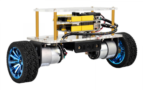
Parameters of balance car
- 1.Motor parameters:
- 2.Working voltage: DC 9-12V
- 3.Motor drive chip: TB6612FNG
- 4.Body posture detection: MPU-6050
- 5.Comes with power control switch
- 6.Comes with Bluetooth control switch for controlling serial communication
Pay special attention to:
The balance shield comes with a slide switch for controlling the Bluetooth communication.
When upload the source code, must turn the slide switch OFF; otherwise, code uploading will fail.
When connecting to the Bluetooth module, should turn the slide switch ON.
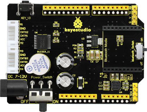
Kit List
The kit packaging contains all electronic components for this self-balancing car. As you work your way through each project, you will learn how to control the car.
Resources
All Info.Download:
https://1drv.ms/u/s!ArhgRvK6-RyJhGZP5VY85WVtDBhL?e=BLmybl
Assembly Steps
(1) Prepare all the components shown below.
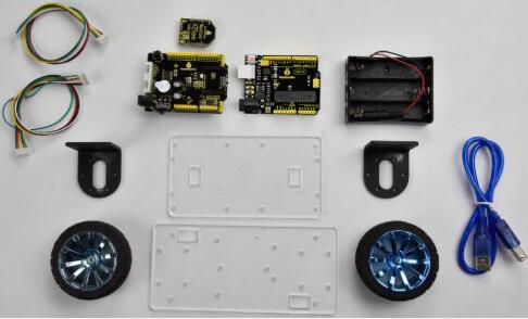
(2) To begin with, we start to install the bottom Acrylic plate.
Find out the parts below:
- Bottom Acrylic plate
- Dual-pass M3*10MM hex copper pillar x 4pcs
- M3*8MM screw x 4pcs
- M3*12MM flat head screw x 2pcs
- M3 nickel plating nut x 2pcs
- Battery case
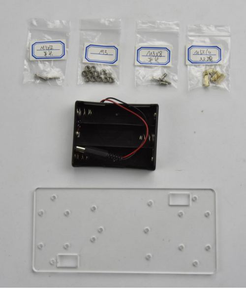
We are now going to mount the battery case and copper pillars on the Acrylic plate.
Fix the 4pcs M3*10MM copper pillar onto the Acrylic plate using 4pcs M3*8MM screws.
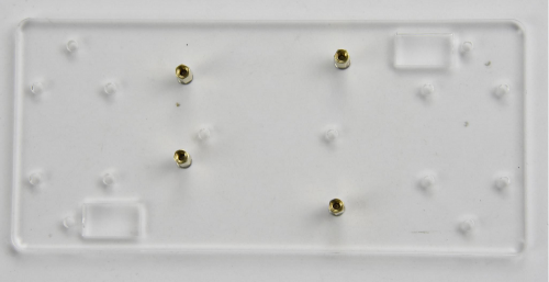
Then Mount the battery case on the Acrylic plate using 2pcs M3*12MM flat head screws and 2pcs M3 nickel plating Nuts.

(3) Next, move on to install the motor and wheel onto bottom Acrylic plate.
Find out the parts below:
- Bottom Acrylic plate mounted with battery case
- M3*12MM round-head screw x 8pcs
- M3 nickel plating nut x 8pcs
- M4*6MM black screw x 2pcs
- Two wheels
- Two black connectors
- Two motors
- Two copper hex couplers
- M2 wrench Type L
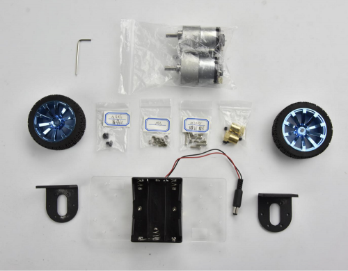
Go to mount the two black connectors onto the Acrylic plate using 8pcs M3*12MM round-head screws and 8pcs M3 nickel plating nuts. Shown below.
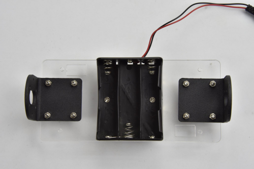
Each motor is equipped with six screws in the bag. Go to mount the two motors on the black connectors using the screws.
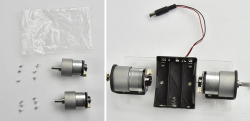
Screw each copper hex couplers with two screws. Then fix the two copper couplers on the two motors using a wrench.
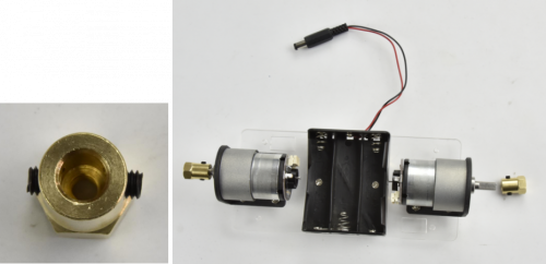
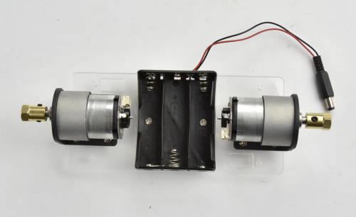
Finally mount the two wheels to the two hex copper couplers using 2pcs M4*6MM black screws.
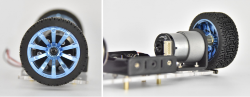
Up to now, the bottom motor wheel are installed well!
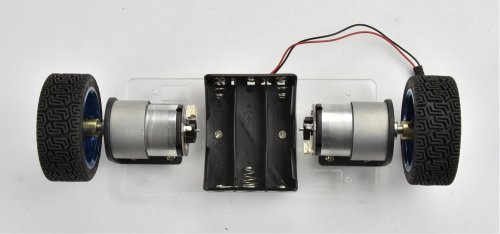
(4) The final step is to install the control board and the top Acrylic plate.
- Top Acrylic plate
- REV4 control board
- keyestudio balance shield
- Bluetooth XBee module HC-06
- M3*6MM round-head screw x 3pcs
- M3*45MM copper pillar x 4pcs
- M3*8MM round-head screw x 8pcs
- 6pin 30CM connector wire x 2pcs
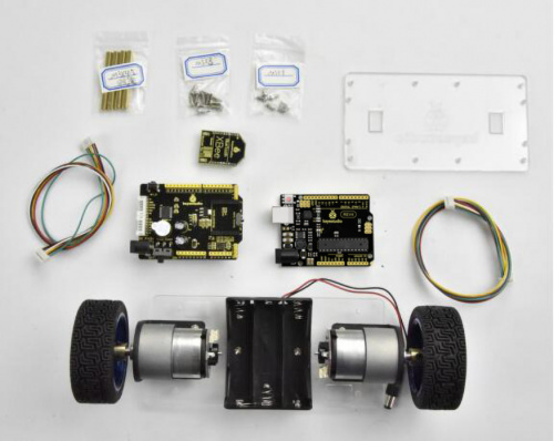
Go to screw the REV4 control board onto the 4pcs M3*10MM copper pillars mounted on the Acrylic plate with 3pcs M3*6MM round-head screws.
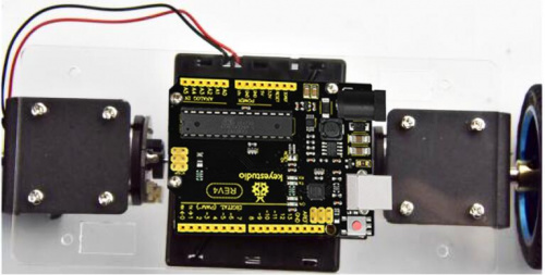
Then stack the keyestudio balance shield onto REV4 control board. And plug the Bluetooth XBee module HC-06 into the balance shield.
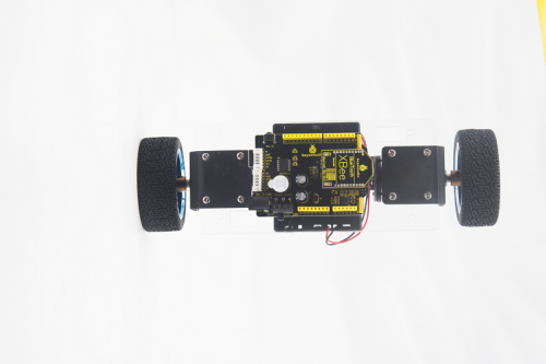
Go to connect the motor to the balance shield using 6pin PH2.0 30CM connector wire. Simply connect the motor to the nearest motor connector.
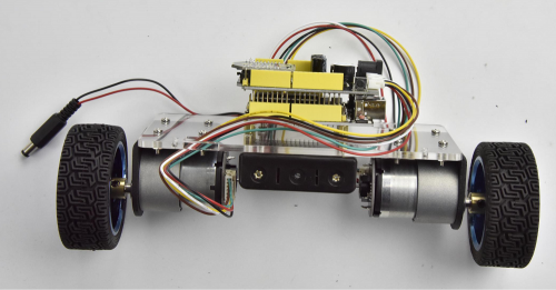
After that, screw the 4pcs M3*45MM copper pillars on the Acrylic plate with 4pcs M3*8MM round head screws. And connect well the battery plug to DC black jack of REV4.
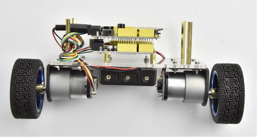
The back view is showed below:
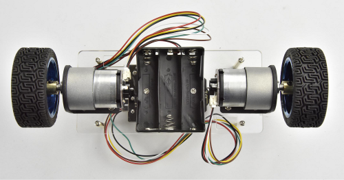
The final part is to install the top Acrylic plate onto the 4pcs M3*45MM copper pillars with 4pcs M3*8MM round-head screws.
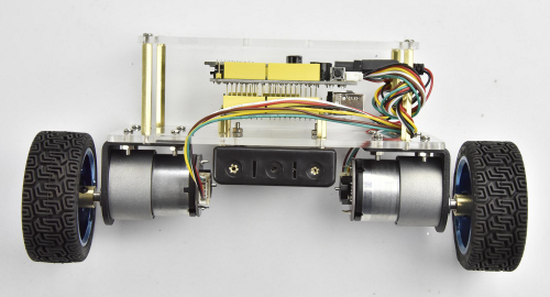
Congrats! The balance car is installed well.
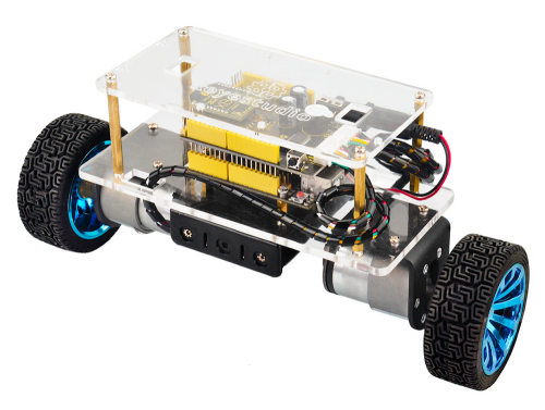
Project 1: Getting Started with Main Board and ARDUINO
The REV4 Control Board
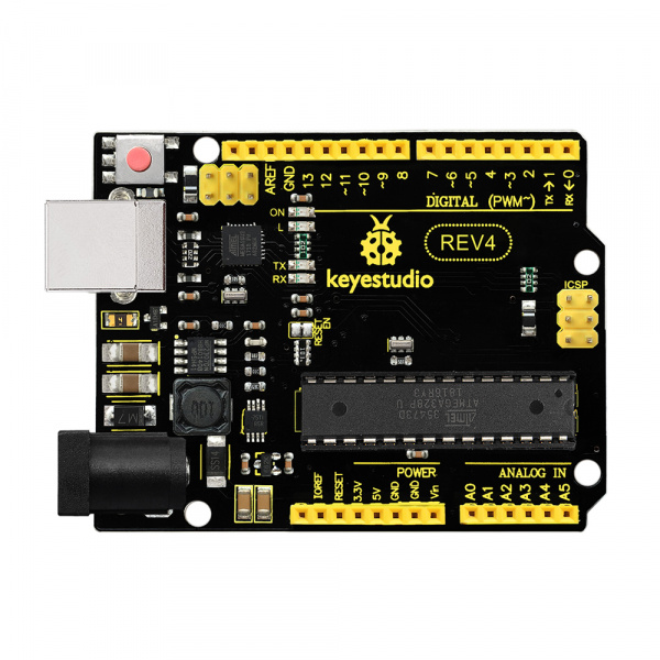
When it comes to using the REV4 as core of our robot, the REV4 is the best board to get started with electronics and coding. If this is your first experience tinkering with the platform, the REV4 is the most robust board you can start playing with.
Well, let's at first have a look at this REV4 board.
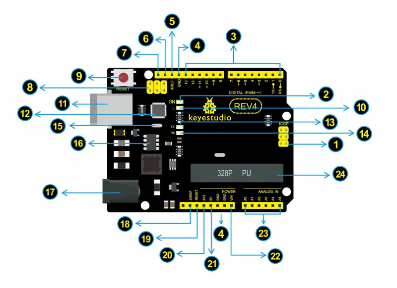
The Balance Car Shield
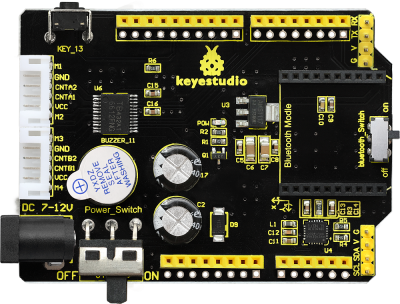
The balance shield is an important part for this balance car. With it, you can DIY the balance car more simple.
It is fully compatible with REV4 board; just stack it onto the control board.
The balance shield comes with a 6612FNG chip for driving two DC motors; two white connectors for connecting DC motor; a DC power jack for powering on the shield and REV4;
Also comes with a large slide switch for controlling the power switch; a MPU-6050 for testing the posture; a XBEE Bluetooth interface for connecting Bluetooth module to communicate with Android devices; a small slide switch for controlling Bluetooth module’s communication; also comes with a button and an active buzzer.
The control pins of REV4 are all brought out as female header on the shield; the serial port and I2C communication pins are brought out as pin headers.
Note: connect the motor to the motor’s connector on the shield.

Installing Arduino IDE
When you get the REV4 development board, first you should install the software and driver of Arduino. You can see all the Arduino software versions from the link below:
https://www.arduino.cc/en/Main/OldSoftwareReleases#1.5.x
Or you can browse the ARDUINO website at this link, https://www.arduino.cc, pop up the following interface.

Then click the SOFTWARE on the browse bar, you will have two options ONLINE TOOLS and DOWNLOADS.

Click DOWNLOADS, it will appear the latest software version of ARDUINO 1.8.5 shown as below.

In this software page, on the right side you can see the version of development software for different operating systems. So ARDUINO has a rather powerful compatibility. You should download the software that is compatible with the operating system of your computer.
In our project, we will take WINDOWS system as an example here. There are also two options under Windows system, one is installed version, the other is non-installed version.
For simple installed version, first click Windows Installer, you will get the following page.
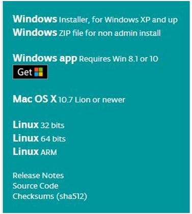

This way you just need to click JUST DOWNLOAD, then click the downloaded file to install it.
For non-installed version, first click Windows ZIP file, you will also get the pop-up interface as the above figure.
Click JUST DOWNLOAD, and when the ZIP file is downloaded well to your computer, you can directly unzip the file and then click the icon of ARDUINO program to start it.
Installing Arduino (Windows)
Install Arduino with the exe. Installation package
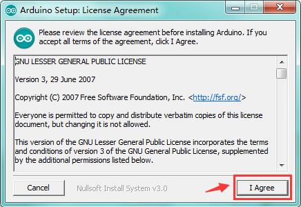
Click“I Agree”to see the following interface.
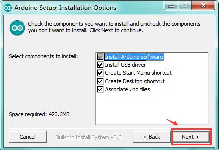
Click “Next”. Pop up the interface below.
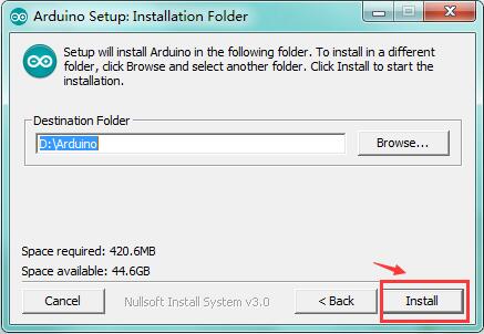
You can press Browse… to choose an installation path or directly type in the directory you want.
Then click “Install” to initiate installation.
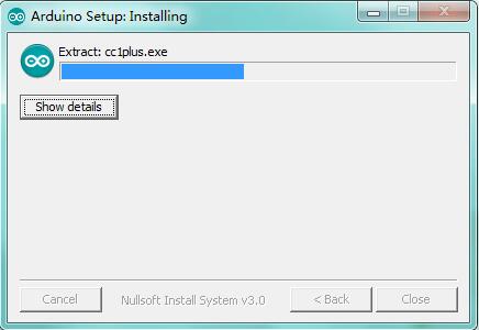
Wait for the installing process, if appear the interface of Window Security, just continue to click Install to finish the installation.
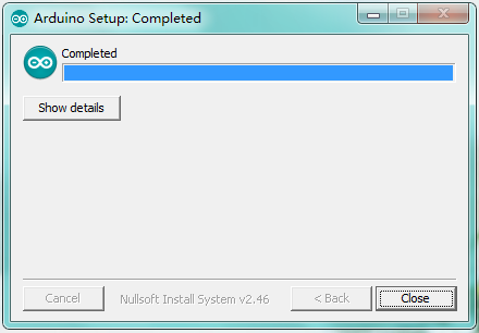
All right, up to now, you have completed the Arduino setup! The following icon will appear on your PC desktop.

Double-click the icon of Arduino to enter the desired development environment shown as below.
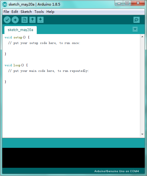
Installing Driver
Next, we will introduce the driver installation of REV4 development board. The driver installation may have slight differences in different computer systems. So in the following let’s move on to the driver installation in the WIN 7 system.
The Arduino folder contains both the Arduino program itself and the drivers that allow the Arduino to be connected to your computer by a USB cable. Before we launch the Arduino software, you are going to install the USB drivers.
Plug one end of your USB cable into the Arduino and the other into a USB socket on your computer.
When you connect REV4 board to your computer at the first time, right click the icon of your “Computer” —>for “Properties”—> click the “Device manager”, under “Other Devices”, you should see an icon for“Unknown device” with a little yellow warning triangle next to it. This is your Arduino.
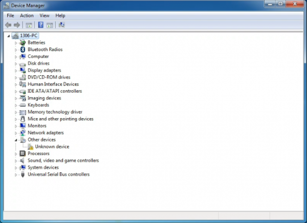
Then right-click on the device and select the top menu option (Update Driver Software...) shown as the figure below..
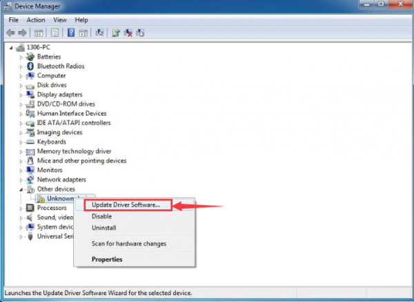
It will then be prompted to either “Search Automatically for updated driver software” or “Browse my computer for driver software”. Shown as below. In this page, select “Browse my computer for driver software”.
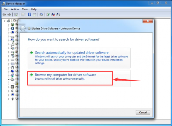
After that, select the option to browse and navigate to the “drivers” folder of Arduino installation.
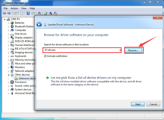
Click “Next” and you may get a security warning, if so, allow the software to be installed. Shown as below.
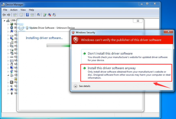
Once the software has been installed, you will get a confirmation message. Installation completed, click “Close”.
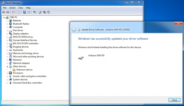
Up to now, the driver is installed well. Then you can right click “Computer” —>“Properties”—>“Device manager”, you should see the device as the figure shown below.
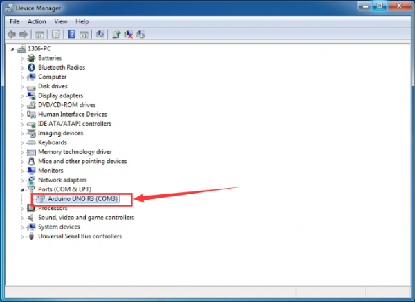
Example Use of ARDUINO IDE
STEP 1: Open Arduino
In the previous, we have introduced the driver installation of REV4 development board. So this time let’s first have basic understanding of the development environment of ARDUINO. After that, you will learn how to upload the program to Arduino board.
First of all, open the unzipped folder of ARDUINO development software and click icon of ARDUINO to open the software, as the figure shown below.
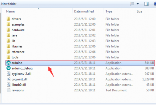
STEP 2: Build Projects
When open the Arduino software, you will have two options as below:
- Build a new project
- Open an exiting project example
If you want to build a new project, please select “File”→then click “New”, you will see the software interface as follows.
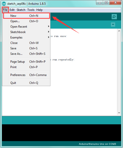
![]()
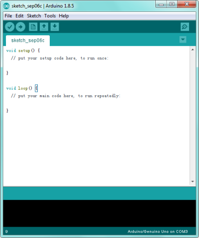
If you want to open an example project, please select File→Example→Basics→Blink. Shown below.
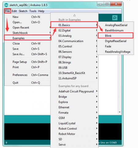
![]()
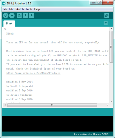
STEP 3: Select Arduino Board
On the Arduino software, you should click Tools→Board , select the correct board. Here in our tutorial we should select Arduino UNO. Shown as below.
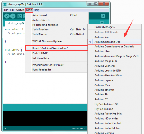
STEP 4: Select Serial Port
If you are not sure which port is correct, at first directly open the Control Panel of your computer, then click to open Device Manager, you can check the COM port here. Shown as below.

Then you should click Tools→Serial Port. It may be COM3 or higher (COM1 and COM2 are usually reserved as hardware serial port).
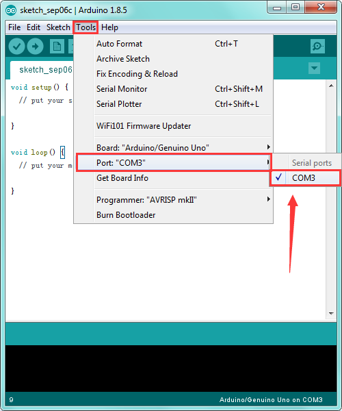
STEP 5: Upload the Code to Your Board
Before showing you how to upload the code to your board, first of all let me introduce the function of each icon on the Tool bar of Arduino IDE. Look at the picture showed below.
![]()
Project 2: Button and Buzzer
Description:
In the previous project, you have learned how to use Arduino software environment.
Want to try it? Great. This project let’s get started with a basic program to enter the programming world of arduino.
The keyestudio balance car shield comes with a button KEY_13 and an active buzzer. To be specific, button is controlled by pin D13 on REV4; active buzzer is controlled by pin D11 on REV4.

In the experiment, we get down to controlling the buzzer with button. When press the button, the buzzer will sound.
The active buzzer comes with oscillating circuit. Actually, simple to set the pin D11 to HIGH, the buzzer can beep. We come to simulate the setting method of passive buzzer. Set different square wave to make the active buzzer output different sounds.
Source Code:
const int buz = 11;    // set the buzzer pin
const int btn = 13;    //set the button pin
int button;    //button variable

void setup()
{
  pinMode(btn,INPUT);       //set to INPUT state
  pinMode(buz,OUTPUT);       //set to OUTPUT state
}

void loop()
{
  button = digitalRead(btn);       //assign the button value to variable button
  if(button == 0)    //if press the button
  {
    delay(10);    //delay time
    if(button == 0)     //judge again, if the button is pressed
    {
      buzzer();  // execute the subfunction of buzzer
    }
  }
  else        // button not pressed
  {
    digitalWrite(buz,LOW);    // buzzer not sounds
  }
}

//buzzer makes tick sound
void buzzer()
{
    for(int i=0;i<50;i++)
    {
    digitalWrite(buz,HIGH);
    delay(1);
    digitalWrite(buz,LOW);
    delay(1);
    }
    delay(50);
    for(int i=0;i<50;i++)
    {
    digitalWrite(buz,HIGH);
    delay(1);
    digitalWrite(buz,LOW);
    delay(1);
    }
}
Test Result:
Installed well the balance car, upload the source code and power on; turn the slide switch ON and then press the KEY_13 button on the shield.
The active buzzer on the balance shield will sound; otherwise, it will not sound.

Project 3: TB6612 Motor Driving
Description:
We have tested the balance shield’s button and buzzer. Now, we are going to mainly test the motor driving ability.
In the project, we control the right motor’s direction by pin D8 D12 on REV4; speed is controlled by pin D10. The left motor’s direction by pin D7 D6 on REV4; speed is controlled by pin D9.
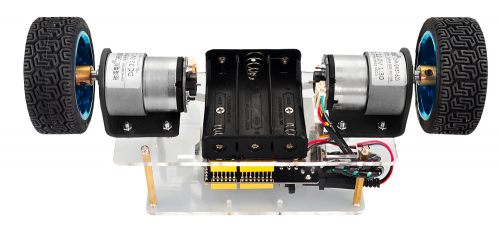
The specified control method refers to the table below:

The D9 D10 are PWM pins, which can be used as Digital output or Analog output.
If used as Analog output, it needs to call the analogWrite() function of ARDUINO, and this analogWrite() function can be controlled in the range of 0-255.
A call to analogWrite() is on a scale of 0-255, such that analogWrite(255) requests a 100% duty cycle (always on), and analogWrite(127) is a 50% duty cycle (on half the time).
In the code, the greater the PWM value set by pin D9 and D10, the faster the two motors’ speed.
In the following, we only simply set the two motors to turn forward and backward.
Source Code:
//TB6612 pins
const int right_R1=8;
const int right_R2=12;
const int PWM_R=10;
const int left_L1=7;
const int left_L2=6;
const int PWM_L=9;

void setup()
{
  Serial.begin(9600);          //set the baud rate to 9600

  pinMode(right_R1,OUTPUT);     // set all TB6612pins to OUTPUT
  pinMode(right_R2,OUTPUT);
  pinMode(PWM_R,OUTPUT);
  pinMode(left_L1,OUTPUT);
  pinMode(left_L2,OUTPUT);
  pinMode(PWM_L,OUTPUT);
}

void loop()
{
  // two motors turn forward
  digitalWrite(right_R1,HIGH);
  digitalWrite(right_R2,LOW);
  digitalWrite(left_L1,HIGH);
  digitalWrite(left_L2,LOW);
  analogWrite(PWM_R,100);   // write into PWM value 0~255(speed)
  analogWrite(PWM_L,100);
}
Test Result:
Installed well the balance car, upload the source code and power on; turn the slide switch ON.
Both left and right motors start to turn forward.

Project 4: Hall Encoder Test
Description:
We have introduced how to set the speed of right and left motor by PWM value of D9 D10.
But how to get the specified speed? Well, we can test it using the motor’s built-in Hall encoder.
In this project, you will learn how to calculate the specified speed by the number of pulses got from Hall encoder within 100ms.
Source Code:
//TB6612 pins
const int right_R1=8;
const int right_R2=12;
const int PWM_R=10;
const int left_L1=7;
const int left_L2=6;
const int PWM_L=9;

const int PinA_left = 5;    // set the left motor’s pulse pin to D5
const int PinA_right = 4;    //set the right motor’s pulse pin to D4

int times=0,newtime=0,d_time=100;   // time, new time, time interval
int valA=0,valB=0,flagA=0,flagB=0;    //variable valA and valB for calculating the number of pulse

void setup()
{
  Serial.begin(9600);

  pinMode(right_R1,OUTPUT);    // set the TB6612 pins to OUTPUT
  pinMode(right_R2,OUTPUT);
  pinMode(PWM_R,OUTPUT);
  pinMode(left_L1,OUTPUT);
  pinMode(left_L2,OUTPUT);
  pinMode(PWM_L,OUTPUT);

  pinMode(PinA_left,INPUT);    // set the pulse pin to INPUT
  pinMode(PinA_right,INPUT);

}

void loop()
{
  //both motors turn forward
  digitalWrite(right_R1,HIGH);
  digitalWrite(right_R2,LOW);
  digitalWrite(left_L1,HIGH);
  digitalWrite(left_L2,LOW);
  analogWrite(PWM_R,100);   //write into PWM value 0~255(speed)
  analogWrite(PWM_L,200);

  newtime=times=millis();     //make newtime and times equal to the time the program runs to here
  while((newtime-times)<d_time)    //if less than the setting d_time,always loop
  {
    if(digitalRead(PinA_left)==HIGH&&flagA==0)   // if detects HIGH
    {
      valA++;      //valA plus 1
      flagA=1;
    }
    if(digitalRead(PinA_left)==LOW&&flagA==1)    // if LOW
    {
      valA++;     //valA plus 1
      flagA=0;
    }

    if(digitalRead(PinA_right)==HIGH&&flagB==0)
    {
      valB++;
      flagB=1;
    }
    if(digitalRead(PinA_right)==LOW&&flagB==1)
    {
      valB++;
      flagB=0;
    }
    newtime=millis();        //newtime equals to the time the program runs to here
  }
  Serial.println(valA);      // print out the value of valA and B
  Serial.println(valB);
  valA=valB=0;             //set to 0
}
Test Result:
Installed well the balance car, upload the source code and power on; turn the slide switch ON.
Then open the Arduino IDE, set the baud rate to 9600, the serial monitor will pop up the number of pulse got from Hall encoder within 100ms ( correspond to left and right motor).
See the figure below.
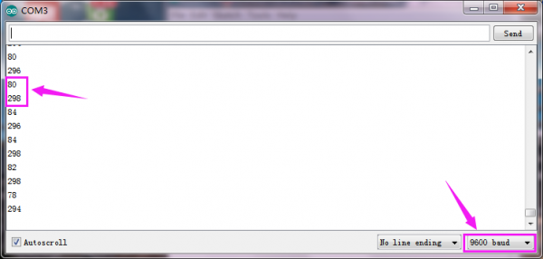
Project 5: Internal Timer Interrupt
Description:
In previous section, you have learned how to get the number of pulses by Hall encoder of motor within 100ms.
Now, we will use the built-in internal timer (timer2) of REV4 board. Calculate out the specified speed by the number of pulses got from Hall encoder within 100ms.
Source Code:
Before test the source code, do remember to add the corresponding library.
You can refer to the method in the link below:
https://wiki.keyestudio.com/How_to_Install_Arduino_Library
#include <MsTimer2.h>

//TB6612 pins
const int right_R1=8;
const int right_R2=12;
const int PWM_R=10;
const int left_L1=7;
const int left_L2=6;
const int PWM_L=9;

const int PinA_left = 5;        //set the left motor’s pulse pin to D5
const int PinA_right = 4;       //set the right motor’s pulse pin to D4

int times=0,newtime=0,d_time=100;   // time, new time, time interval
int valA=0,valB=0,flagA=0,flagB=0;   //variable valA and valB for calculating the number of pulse

void setup()
{
  Serial.begin(9600);

  pinMode(right_R1,OUTPUT);     //set the TB6612 pins to OUTPUT
  pinMode(right_R2,OUTPUT);
  pinMode(PWM_R,OUTPUT);
  pinMode(left_L1,OUTPUT);
  pinMode(left_L2,OUTPUT);
  pinMode(PWM_L,OUTPUT);

  pinMode(PinA_left,INPUT);      // set the pulse pin to INPUT
  pinMode(PinA_right,INPUT);

  MsTimer2::set(100, inter); // trigger an interrupt per 100ms
  MsTimer2::start();    // start interrupt
}

void loop()
{
  //both motors turn forward
  digitalWrite(right_R1,HIGH);
  digitalWrite(right_R2,LOW);
  digitalWrite(left_L1,HIGH);
  digitalWrite(left_L2,LOW);
  analogWrite(PWM_R,100);    //write into PWM value 0~255(speed)
  analogWrite(PWM_L,200);

  if(digitalRead(PinA_left)==HIGH&&flagA==0)     // calculate the pulse value
    {
      valA++;
      flagA=1;
    }
    if(digitalRead(PinA_left)==LOW&&flagA==1)
    {
      valA++;
      flagA=0;
    }

    if(digitalRead(PinA_right)==HIGH&&flagB==0)
    {
      valB++;
      flagB=1;
    }
    if(digitalRead(PinA_right)==LOW&&flagB==1)
    {
      valB++;
      flagB=0;
    }

}

//interrupt function
void inter()
{
    sei();    //allow whole interrupts
    Serial.print("valA = ");     //print out the pulse value on serial monitor
    Serial.println(valA);
    Serial.print("valB = ");
    Serial.println(valB);
    valA = valB = 0;
}
Test Result
Installed well the balance car, power on and upload the source code to the board;
Turn the slide switch ON.
Then open the monitor of Arduino IDE, set the baud rate to 9600.
The serial monitor will pop up the number of pulse got from Hall encoder within 100ms ( correspond to left and right motor).
See the figure below.
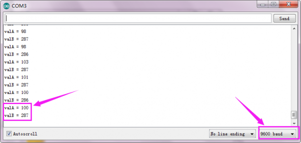
Project 6: Bluetooth Test
Description:
The kit contains a Bluetooth XBee module, which is compatible with Android system.
Keyestudio Bluetooth XBee wireless module HC-06 has features of compact size, compatible with XBEE shield, and suitable for various 3.3V MCU systems. It also comes with efficient on-board antenna.
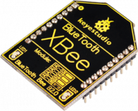
More contents check the link here.
https://wiki.keyestudio.com/Ks0144_keyestudio_XBee_Bluetooth_Wireless_Module_HC-06
In this project, go to learn how to use Bluetooth APP to make the balance car communicate with Android Bluetooth. You are able to use Bluetooth APP to randomly control the balance car move.
Note:
The keyestudio balance shield comes with a slide switch for controlling the Bluetooth communication.
When upload the source code, must turn the switch OFF; or else code uploading fails.
When connect to the Bluetooth module, should turn the switch ON.
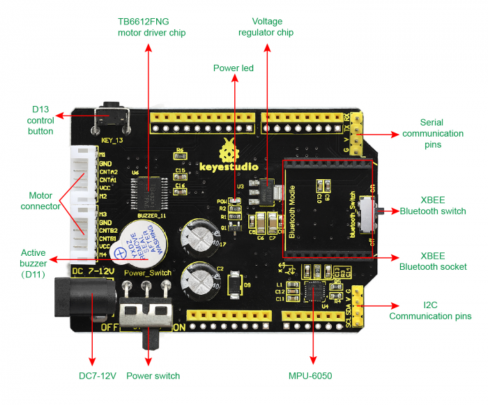
How to use Bluetooth APP?
- Installed the balance car, upload the source code and power on; turn the power switch ON; turn the Bluetooth switch ON.
- Install the Bluetooth APP, then you can see the right icon on your phone.
Click the link below to download the APP:
https://drive.google.com/open?id=1L69xdfmOvfhg0Wjh_p2FrtRkhs1h0fEu
- Tap to open the Bluetooth APP; you will see the interface shown below.
- Tap the HC-06 (search at the first time is a address, so tap the address); the PIN is 1234.
- Finally you will see the paired device.
tap the key ![]() , the two motors of balance car stop;
tap the key
, the two motors of balance car stop;
tap the key ![]() , the two motors of balance car turn backward.
, the two motors of balance car turn backward.
Source Code:
//TB6612 pins
const int right_R1=8;
const int right_R2=12;
const int PWM_R=10;
const int left_L1=7;
const int left_L2=6;
const int PWM_L=9;
char val;   // Bluetooth variable

void setup()
{
  Serial.begin(9600);

  pinMode(right_R1,OUTPUT);   //set TB6612 pins OUTPUT
  pinMode(right_R2,OUTPUT);
  pinMode(PWM_R,OUTPUT);
  pinMode(left_L1,OUTPUT);
  pinMode(left_L2,OUTPUT);
  pinMode(PWM_L,OUTPUT);
}

void loop()
{
  if(Serial.available())    //if serial buffer value is available
  {
    val = Serial.read();      //assign the value read from serial port to val
    Serial.println(val);
    switch(val)             //switch statement
    {
      case 'F': front(); break;     //motor turns front
      case 'B': back(); break;       //turn back
      case 'S': Stop();break;    //stop
    }
  }
}

//turn front
void front()
{
  digitalWrite(right_R1,HIGH);
  digitalWrite(right_R2,LOW);
  digitalWrite(left_L1,HIGH);
  digitalWrite(left_L2,LOW);
  analogWrite(PWM_R,100);
  analogWrite(PWM_L,100);
}
//turn back
void back()
{
  digitalWrite(right_R1,LOW);
  digitalWrite(right_R2,HIGH);
  digitalWrite(left_L1,LOW);
  digitalWrite(left_L2,HIGH);
  analogWrite(PWM_R,100);
  analogWrite(PWM_L,100);
}
//stop
void Stop()
{
  digitalWrite(right_R1,LOW);
  digitalWrite(right_R2,HIGH);
  digitalWrite(left_L1,LOW);
  digitalWrite(left_L2,HIGH);
  analogWrite(PWM_R,0);
  analogWrite(PWM_L,0);
}
Project 7: MPU6050 Test
Description:
When DIY the balance car, should obtain its posture at first. The most used is through accelerometer and gyroscope.
In theory, only need two-axis accelerometer (Z-axis in the straight direction and the Y-axis along the moving direction of the car) and a single-axis gyroscope (the angular velocity in the X-axis direction of the car wheel are calculated).
In this project, we use the built-in MPU-6050 chip of keyestudio balance shield to test the data of the three-axis accelerometer and the three-axis gyroscope, printing out it on the serial monitor.
The acceleration range is +-2g; the gyroscope range is +-250°/S.
Source Code:
#include <Wire.h>

long accelX, accelY, accelZ;      // set to overall variable; can be used directly inside the function.
float gForceX, gForceY, gForceZ;

long gyroX, gyroY, gyroZ;
float rotX, rotY, rotZ;

void setup() {
  Serial.begin(9600);
  Wire.begin();
  setupMPU();
}

void loop() {
  recordAccelRegisters();
  recordGyroRegisters();
  printData();
  delay(100);
}

void setupMPU(){
  // REGISTER 0x6B/REGISTER 107:Power Management 1
  Wire.beginTransmission(0b1101000); //This is the I2C address of the MPU (b1101000/b1101001 for AC0 low/high datasheet Sec. 9.2)
  Wire.write(0x6B); //Accessing the register 6B/107 - Power Management (Sec. 4.30)
  Wire.write(0b00000000); //Setting SLEEP register to 0, using the internal 8 Mhz oscillator
  Wire.endTransmission();

  // REGISTER 0x1b/REGISTER 27:Gyroscope Configuration
  Wire.beginTransmission(0b1101000); //I2C address of the MPU
  Wire.write(0x1B); //Accessing the register 1B - Gyroscope Configuration (Sec. 4.4)
  Wire.write(0x00000000); //Setting the gyro to full scale +/- 250deg./s (转化为rpm:250/360 * 60 = 41.67rpm) ;The highest can be converted to 2000deg./s
  Wire.endTransmission();

  // REGISTER 0x1C/REGISTER 28:ACCELEROMETER CONFIGURATION
  Wire.beginTransmission(0b1101000); //I2C address of the MPU
  Wire.write(0x1C); //Accessing the register 1C - Acccelerometer Configuration (Sec. 4.5)
  Wire.write(0b00000000); //Setting the accel to +/- 2g(if choose +/- 16g,the value would be 0b00011000)
  Wire.endTransmission();
}

void recordAccelRegisters() {
  // REGISTER 0x3B~0x40/REGISTER 59~64
  Wire.beginTransmission(0b1101000); //I2C address of the MPU
  Wire.write(0x3B); //Starting register for Accel Readings
  Wire.endTransmission();
  Wire.requestFrom(0b1101000,6); //Request Accel Registers (3B - 40)

  // Use left shift << and bit operations |  Wire.read() read once 1bytes,and automatically read the data of the next address on the next call.
  while(Wire.available() < 6);  // Waiting for all the 6 bytes data to be sent from the slave machine (Must wait for all data to be stored in the buffer before reading)
  accelX = Wire.read()<<8|Wire.read(); //Store first two bytes into accelX (Automatically stored as a defined long value)
  accelY = Wire.read()<<8|Wire.read(); //Store middle two bytes into accelY
  accelZ = Wire.read()<<8|Wire.read(); //Store last two bytes into accelZ
  processAccelData();
}

void processAccelData(){
  gForceX = accelX / 16384.0;     //float = long / float
  gForceY = accelY / 16384.0;
  gForceZ = accelZ / 16384.0;
}

void recordGyroRegisters()
{
  // REGISTER 0x43~0x48/REGISTER 67~72
  Wire.beginTransmission(0b1101000); //I2C address of the MPU
  Wire.write(0x43); //Starting register for Gyro Readings
  Wire.endTransmission();
  Wire.requestFrom(0b1101000,6); //Request Gyro Registers (43 ~ 48)
  while(Wire.available() < 6);
  gyroX = Wire.read()<<8|Wire.read(); //Store first two bytes into accelX
  gyroY = Wire.read()<<8|Wire.read(); //Store middle two bytes into accelY
  gyroZ = Wire.read()<<8|Wire.read(); //Store last two bytes into accelZ
  processGyroData();
}

void processGyroData() {
  rotX = gyroX / 131.0;
  rotY = gyroY / 131.0;
  rotZ = gyroZ / 131.0;
}

void printData() {
  Serial.print("Gyro (deg)");
  Serial.print(" X=");
  Serial.print(rotX);
  Serial.print(" Y=");
  Serial.print(rotY);
  Serial.print(" Z=");
  Serial.print(rotZ);
  Serial.print(" Accel (g)");
  Serial.print(" X=");
  Serial.print(gForceX);
  Serial.print(" Y=");
  Serial.print(gForceY);
  Serial.print(" Z=");
  Serial.println(gForceZ);
}
Test Result:
Installed well the balance car, upload the source code and power on; turn the slide switch ON.
Then open the Arduino IDE, set the baud rate to 9600, the serial monitor will pop up the value.
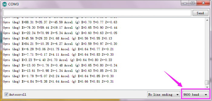
Project 8: Calculating Inclined Angle And Angular Velocity Values
Description:
In the previous project, we have used accelerometer and gyroscope to get the car’s posture.
In this lesson, we use the data measured by MPU-6050 chip to directly get the posture of balance car.
You will learn how to calculate the tilt angle and angular velocity value detected by balance car. Show the test result on the serial monitor.
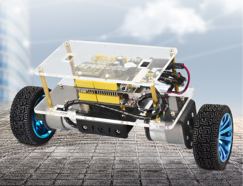
Source Code:
Note:Before test the source code, do remember to add the corresponding library.
You can refer to the method in the link:
https://wiki.keyestudio.com/How_to_Install_Arduino_Library
#include <MPU6050.h>      //MPU6050 library
#include <Wire.h>        //IIC communication library

MPU6050 mpu6050;     //Instantiate an MPU6050 object; name mpu6050
int16_t ax, ay, az, gx, gy, gz;     //Define three-axis acceleration, three-axis gyroscope variables

float Angle;   //angle variable
int16_t Gyro_x;   //Angular velocity variable

void setup()
{
  // Join the I2C bus
  Wire.begin();                            //Join the I2C bus sequence
  Serial.begin(9600);                       //open serial monitor and set the baud rate to 9600
  delay(1500);
  mpu6050.initialize();                       //initialize MPU6050
  delay(2);
}

void loop()
{
  mpu6050.getMotion6(&ax, &ay, &az, &gx, &gy, &gz);     //IIC to get MPU6050 six-axis data  ax ay az gx gy gz
  Angle = -atan2(ay , az) * (180/ PI);           //Radial rotation angle calculation formula; the negative sign is direction processing
  Gyro_x = -gx / 131;              //The X-axis angular velocity calculated by the gyroscope; the negative sign is the direction processing
  Serial.print("Angle = ");
  Serial.print(Angle);
  Serial.print("   Gyro_x = ");
  Serial.println(Gyro_x);
}
Test Result
Installed well the balance car, upload the source code and power on; turn the slide switch ON.
Then open the Arduino IDE, set the baud rate to 9600, the serial monitor will pop up the value.
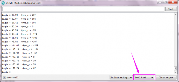
How to use Kalman filtering to calculate the angel?
What’s Kalman filtering ?
Kalman filtering is an algorithm that uses the linear system state equation to estimate the state of the system through the input and output of the system.
Since the observed data includes the effects of noise and interference in the system, the optimal estimate can also be seen as a filtering process.
Accelerometer data cannot always be trusted 100% due to original data acquired by the MPU6050.
Why?
The accelerometer measures the inertial force, which may be caused by gravitational force (ideally only gravitational), but it may also be caused by the acceleration (motion) of the device.
Therefore, even if the accelerometer is in a relatively stable state, it is still very sensitive to vibration and mechanical noise.
That is, the individual number of inclination angles obtained by using the value of the 3-axis acceleration is erroneous, and the error is large. Then you need to use a gyroscope to eliminate any accelerometer errors.
But how is this done? Is there no noise in the gyroscope?
The gyroscope is not without noise, but because it measures rotation, it is less sensitive to linear mechanical motion (the type of noise the accelerometer is subjected to).
However, the gyroscope has other types of problems, such as drift (does not return to zero rate values when the rotation stops).
Nonetheless, by averaging the data from the accelerometer and the gyroscope, we can obtain a better estimate than the current device’s tilt angle obtained by using the accelerometer data alone.
Therefore, in order to obtain a smaller, more stable angle, we need to perform Kalman filtering on the inclination angle θ calculated by the acceleration and the measured angular velocity value θ' of the gyroscope.
In this project,we use Kalman filter to calculate the balance angle and angular velocity of the balance car, displaying the tested data on the serial monitor.
Source Code:
Note: Before test the source code, do remember to add the corresponding library.
You can refer to the method in the link:
https://wiki.keyestudio.com/How_to_Install_Arduino_Library
#include <MPU6050.h>      //MPU6050 library
#include <Wire.h>        //IIC communication library

MPU6050 mpu6050;     //Instantiate an MPU6050 object; name mpu60500
int16_t ax, ay, az, gx, gy, gz;     //Define three-axis acceleration, three-axis gyroscope variables
float Angle;
float Gyro_x,Gyro_y,Gyro_z;  //calculate angular velocity of each axis by gyroscope

///////////////////////Kalman_Filter////////////////////////////
float Q_angle = 0.001;  //Covariance of gyroscope noise
float Q_gyro = 0.003;    //Covariance of gyroscope drift noise
float R_angle = 0.5;    //Covariance of accelerometer
char C_0 = 1;
float dt = 0.005; //The value of dt is the filter sampling time.
float K1 = 0.05; // a function containing the Kalman gain is used to calculate the deviation of the optimal estimate.
float K_0,K_1,t_0,t_1;
float angle_err;
float q_bias;    //gyroscope drift

float accelz = 0;
float angle;
float angle_speed;

float Pdot[4] = { 0, 0, 0, 0};
float P[2][2] = {{ 1, 0 }, { 0, 1 }};
float  PCt_0, PCt_1, E;
//////////////////////Kalman_Filter/////////////////////////

void setup()
{
  // Join the I2C bus
  Wire.begin();                            //Join the I2C bus sequence
  Serial.begin(9600);                       //open serial monitor and set the baud rate to 9600
  delay(1500);
  mpu6050.initialize();                       //initialize MPU6050
  delay(2);
}

void loop()
{
  Serial.print("Angle = ");
  Serial.print(Angle);
  Serial.print("  K_angle = ");
  Serial.println(angle);
  Serial.print("Gyro_x = ");
  Serial.print(Gyro_x);
  Serial.print("  K_Gyro_x = ");
  Serial.println(angle_speed);

  mpu6050.getMotion6(&ax, &ay, &az, &gx, &gy, &gz);     //IIC to get MPU6050 six-axis ax ay az gx gy gz
  angle_calculate(ax, ay, az, gx, gy, gz, dt, Q_angle, Q_gyro, R_angle, C_0, K1);      //obtain angle and KalmanFilter
}

/////////////////////////////angle calculate///////////////////////
void angle_calculate(int16_t ax,int16_t ay,int16_t az,int16_t gx,int16_t gy,int16_t gz,float dt,float Q_angle,float Q_gyro,float R_angle,float C_0,float K1)
{
  Angle = -atan2(ay , az) * (180/ PI);           //Radial rotation angle calculation formula; negative sign is direction processing
  Gyro_x = -gx / 131;              //The X-axis angular velocity calculated by the gyroscope; the negative sign is the direction processing
  Kalman_Filter(Angle, Gyro_x);            //KalmanFilter
}
////////////////////////////////////////////////////////////////

///////////////////////////////KalmanFilter/////////////////////
void Kalman_Filter(double angle_m, double gyro_m)
{
  angle += (gyro_m - q_bias) * dt;          //Prior estimate
  angle_err = angle_m - angle;

  Pdot[0] = Q_angle - P[0][1] - P[1][0];    //Differential of azimuth error covariance
  Pdot[1] = - P[1][1];
  Pdot[2] = - P[1][1];
  Pdot[3] = Q_gyro;

  P[0][0] += Pdot[0] * dt;    //The integral of the covariance differential of the prior estimate error
  P[0][1] += Pdot[1] * dt;
  P[1][0] += Pdot[2] * dt;
  P[1][1] += Pdot[3] * dt;

  //Intermediate variable of matrix multiplication
  PCt_0 = C_0 * P[0][0];
  PCt_1 = C_0 * P[1][0];
  //Denominator
  E = R_angle + C_0 * PCt_0;
  //Gain value
  K_0 = PCt_0 / E;
  K_1 = PCt_1 / E;

  t_0 = PCt_0;  //Intermediate variable of matrix multiplication
  t_1 = C_0 * P[0][1];

  P[0][0] -= K_0 * t_0;    //Posterior estimation error covariance
  P[0][1] -= K_0 * t_1;
  P[1][0] -= K_1 * t_0;
  P[1][1] -= K_1 * t_1;

  q_bias += K_1 * angle_err;    //Posterior estimation
  angle_speed = gyro_m - q_bias;   //The differential value of the output value; work out the optimal angular velocity
  angle += K_0 * angle_err; ////Posterior estimation; work out the optimal angle
}
Test Result
Installed well the balance car, upload the source code and power on; turn the slide switch ON.
Then open the Arduino IDE, set the baud rate to 9600, the serial monitor will pop up the value.
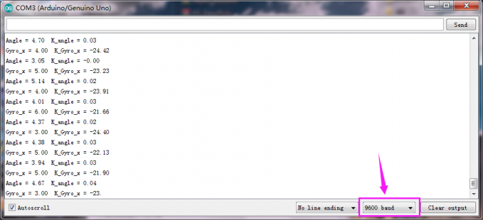
Project 9: PID Principle
Description:
The Proportion of deviation, Integral and the Differential are linearly combined to form a control quantity, then control object by this control quantity. Such a controller is called a PID controller.
In analog control systems, the most common control law for controllers is PID control.
The block diagram of the common analog PID control system is shown below.

The system consists of an analog PID controller and a controlled object.
In the figure, r(t) is a given value; y(t) is the actual output value of the system;
control deviation e(t) equals the given value subtracts the actual output value.
e(t) = r(t) − y(t)
e(t) is the input of the PID control; u(t) is used as the output of the PID controller and the input of the controlled object.
So the control law of the analog PID controller is follows:
- Kp: the proportional coefficient of the controller;
- Ti: the integral time of the controller, also called the integral coefficient;
- Td: the differential time of the controller, also called the differential coefficient.
(1) Proportion part
The mathematical formula of the proportional part is: Kp×e(t)
In the analog PID controller, the proportional link is to react to the moment of deviation.
Once the deviation occurs, the controller immediately produces a control action that causes the control amount to change in the direction of decreasing the deviation.
The strength of the control depends on the proportional coefficient Kp.
The larger the proportional coefficient Kp, the stronger the control effect, the faster the transition process, the smaller the static deviation of the control process.
However, the larger the Kp, the more likely it is to oscillate and to destroy the system stability.
Therefore, the selection of the proportional coefficient Kp must be appropriate to achieve a small transition time and a small and stable static difference.
(2) Integral part
The mathematical formula of the integral part is:

From the formula of the integral part, we can know that as long as there is a deviation, its control effect will continue to increase.
Only when the deviation e(t)=0, its integral can be a constant, and the control effect is not a Increased constant.
It can be seen that the integral part can eliminate the deviation of the system.
Although the adjustment function of the integral link will eliminate the static error, it will reduce the response speed of the system and increase the overshoot of the system.
The larger the integral constant Ti is, the weaker the accumulation of the integral is. At this time, the system does not oscillate during the transition.
Increasing the integral constant Ti can slow down the elimination process of the static error, and the time required to eliminate the deviation is also longer; however, can reduce the amount of overshoot and improve the stability of the system.
When Ti is small, the integral action is strong; oscillation may occur during the system transition time, but the time required to eliminate the deviation is short. Therefore, Ti must be determined according to the specific requirements of actual control.
(3) Differential part
The mathematical formula of the differential part is:
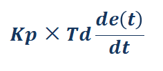
In addition to the desire to eliminate static errors, the actual control system requires an accelerated adjustment process.
At the moment when the deviation occurs, or at the moment of the deviation change, not only the immediate response (the role of the proportional link ) is required, but also the appropriate correction is given in advance according to the trend of the deviation.
In order to achieve this, a differential link can be added to the PI controller to form a PID controller.
The role of the differential link is to prevent changes in the deviation.
It is controlled according to the trend of change (speed of change).
The faster the deviation changes, the larger the output of the differential controller, and the correction can be made before the deviation value becomes larger.
The introduction of differential action will help to reduce the overshoot, overcome the oscillation, and stabilize the system, especially for the high-order system, which speeds up the tracking speed of the system.
However, the effect of differentiation is sensitive to the noise of the input signal.
For those systems with higher noise, the differential signal is generally not used, or the input signal is filtered before the differential action.
The effect of the differential portion is determined by the differential time constant Td
The larger the Td, the stronger the effect of suppressing the variation of the deviation e(t);
The smaller the Td, the weaker the effect of its resistance to the deviation e(t).
The differential part obviously has a great effect on the stability of the system.
By appropriately selecting the differential constant Td, the differential action can be optimized.
Project 10: Upright Loop Adjustment
Description:
In the previous project, we have introduced how to use MPU-6050 chip to calculate the inclined angle and angular velocity value so as to control the car’s balance.
In this section, we will set about to balance the car upright on a horizontal plane via PD (proportion and differential ).
However, if placed on a slope or pushed slightly by hand, the car will accelerate in the inclined direction and fall down.
The corresponding inclined angle value can be printed out on the serial monitor.
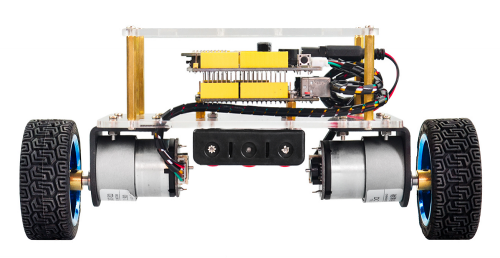
Upright balance principle:
The self-balancing robot stands upright on two coaxial wheels.
The gravity center of robot’s structure design is not on the axis center of the two coaxial wheels and the air flow effect, it will fall in one direction when standing.
To prevent the robot from falling down, it is necessary to add a suitable opposite direction force in the falling direction.
This suitable reverse direction force is provided by a DC geared motor that drives two wheels.
How does a gear DC motor provide a reverse force?
The connection between the self-balancing robot body and the wheels is equivalent to a hinge. Figure below is a simplified diagram of a self-balancing robot.
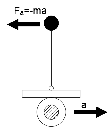
If the wheel accelerates to the right, due to the effect of inertia, the center of gravity of the body will be subjected to a leftward inertial force F.
Just like on the car, if the car accelerates, the person on the car will lean backwards.
But how big is the force in the opposite direction?
Now we come to analyze the force of the self-balancing robot body at an oblique angle θ.
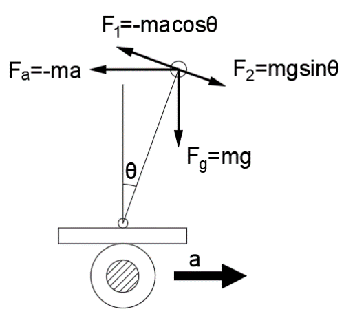
From the force analysis, we can get the Force balance equation below:
![]()
So can turn into the restoring force of robot:

From the force balance equation, the reverse direction force is determined by the acceleration a of the wheel; the magnitude of the acceleration a is determined by the inclination angle θ of the robot body.
Thus, if we know the angle of the inclination angle θ, and then control the value of the acceleration a according to the magnitude of θ;
It seems that the self-balancing robot will not fall down, that is, a negative feedback control.
However, it is difficult for the robot to stand upright and stably through simply adjusting the acceleration a by the inclination angle θ.
Because the value of a is difficult to adjust to the exact value, which is often greater than the appropriate value. So the robot tends to the other direction, swing back and fort in the vertical position, with a larger amplitude.
To stabilize the robot return to the vertical position as soon as possible, you need to increase the damping force.
Supposed that the negative feedback control is that the wheel acceleration a is proportional to the inclination angle θ, and the ratio is k1. That is:
![]()
because the inclination angle θ is relatively small, get: 
![]()
The increased damping force is proportional to the speed of the declination;
The factor of proportionality is k2, and the direction is opposite.
Then can get the final arithmetic of wheel acceleration a:
![]()
θ: inclination angle ; θ': angle speed
K1; k2: the factor of proportionality.
It is also Kp and Kd in the PD algorithm adjustment of the robot upright balance described later.
Up to now, in theory, the balance robot can be balanced upright.
Source Code:
#include <MsTimer2.h>        //internal timer 2
#include <PinChangeInt.h>    //this library can make all pins of arduino REV4 as external interrupt
#include <MPU6050.h>      //MPU6050 library
#include <Wire.h>        //IIC communication library

MPU6050 mpu6050;     //Instantiate an MPU6050 object; name mpu6050
int16_t ax, ay, az, gx, gy, gz;     //Instantiate an MPU6050 object; name mpu6050

//TB6612 pins
const int right_R1=8;
const int right_R2=12;
const int PWM_R=10;
const int left_L1=7;
const int left_L2=6;
const int PWM_L=9;

///////////////////////angle parameters//////////////////////////////
float Angle;
float angle_X; //calculate the inclined angle variable of X-axis by accelerometer
float angle_Y; //calculate the inclined angle variable of Y-axis by accelerometer
float angle0 = 1; //Actual measured angle (ideally 0 degrees)
float Gyro_x,Gyro_y,Gyro_z;  //Angular angular velocity for gyroscope calculation
///////////////////////angle parameters//////////////////////////////

///////////////////////Kalman_Filter////////////////////////////
float Q_angle = 0.001;  //Covariance of gyroscope noise
float Q_gyro = 0.003;    //Covariance of gyroscope drift noise
float R_angle = 0.5;    //Covariance of accelerometer
char C_0 = 1;
float dt = 0.005; // The value of dt is the filter sampling time.
float K1 = 0.05; // a function containing the Kalman gain is used to calculate the deviation of the optimal estimate
float K_0,K_1,t_0,t_1;
float angle_err;
float q_bias;    //gyroscope drift

float accelz = 0;
float angle;
float angleY_one;
float angle_speed;

float Pdot[4] = { 0, 0, 0, 0};
float P[2][2] = {{ 1, 0 }, { 0, 1 }};
float  PCt_0, PCt_1, E;
//////////////////////Kalman_Filter/////////////////////////

//////////////////////PD parameters///////////////////////////////
double kp = 34, ki = 0, kd = 0.62;                   //Angle loop parameter
double setp0 = 0; //Angle balance point
int PD_pwm;  //angle output
float pwm1=0,pwm2=0;

//void anglePWM();

void setup()
{
  //set the control motor’s pin to OUTPUT
  pinMode(right_R1,OUTPUT);
  pinMode(right_R2,OUTPUT);
  pinMode(left_L1,OUTPUT);
  pinMode(left_L2,OUTPUT);
  pinMode(PWM_R,OUTPUT);
  pinMode(PWM_L,OUTPUT);

  //Initial state value
  digitalWrite(right_R1,1);
  digitalWrite(right_R2,0);
  digitalWrite(left_L1,0);
  digitalWrite(left_L2,1);
  analogWrite(PWM_R,0);
  analogWrite(PWM_L,0);

  // Join I2C bus
  Wire.begin();                            //Join the I2C bus sequence
  Serial.begin(9600);                       //open serial monitor, set the baud rate to 9600
  delay(1500);
  mpu6050.initialize();                       //initialize MPU6050
  delay(2);

  //5ms  use timer2 to set the timer interrupt (Note: using timer2 will affect the PWM output of pin3 pin11.)
  MsTimer2::set(5, DSzhongduan);    //5ms execute the function DSzhongduan once
  MsTimer2::start();    // start the interrupt
}

void loop()
{
  Serial.print("angle = ");
  Serial.println(angle);
  Serial.print("Angle = ");
  Serial.println(Angle);

  /*Serial.print("Gyro_x = ");
  Serial.println(Gyro_x);
  Serial.print("K_Gyro_x = ");
  Serial.println(angle_speed);*/

  //Serial.println(PD_pwm);
  //Serial.println(pwm1);
  //Serial.println(pwm2);
}

/////////////////////////////////interrupt////////////////////////////
void DSzhongduan()
{
  sei();  //Allow overall interrupt
  mpu6050.getMotion6(&ax, &ay, &az, &gx, &gy, &gz);     //IIC to get MPU6050 six-axis data ax ay az gx gy gz
  angle_calculate(ax, ay, az, gx, gy, gz, dt, Q_angle, Q_gyro, R_angle, C_0, K1);      //get angle and Kalman_Filter
  PD();         // angle loop of PD control
  anglePWM();
}
///////////////////////////////////////////////////////////

/////////////////////////////angle calculation///////////////////////
void angle_calculate(int16_t ax,int16_t ay,int16_t az,int16_t gx,int16_t gy,int16_t gz,float dt,float Q_angle,float Q_gyro,float R_angle,float C_0,float K1)
{
  Angle = -atan2(ay , az) * (180/ PI);           //Radial rotation angle calculation formula; negative sign is direction processing
  Gyro_x = -gx / 131;              //The X-axis angular velocity calculated by the gyroscope; the negative sign is the direction processing
  Kalman_Filter(Angle, Gyro_x);            //  Kalman Filter
  //Rotation Angle Z axis parameter
  Gyro_z = -gz / 131;                      //Z-axis angular velocity
  //accelz = az / 16.4;

  float angleAx = -atan2(ax, az) * (180 / PI); //Calculate the angle with the x-axis
  Gyro_y = -gy / 131.00; //Y-axis angular velocity
  Yiorderfilter(angleAx, Gyro_y); //first-order filter
}
////////////////////////////////////////////////////////////////

///////////////////////////////KalmanFilter/////////////////////
void Kalman_Filter(double angle_m, double gyro_m)
{
  angle += (gyro_m - q_bias) * dt;          //Prior estimate
  angle_err = angle_m - angle;

  Pdot[0] = Q_angle - P[0][1] - P[1][0];    //Differential of azimuth error covariance
  Pdot[1] = - P[1][1];
  Pdot[2] = - P[1][1];
  Pdot[3] = Q_gyro;

  P[0][0] += Pdot[0] * dt;    //A priori estimation error covariance differential integral
  P[0][1] += Pdot[1] * dt;
  P[1][0] += Pdot[2] * dt;
  P[1][1] += Pdot[3] * dt;

  //Intermediate variable of matrix multiplication
  PCt_0 = C_0 * P[0][0];
  PCt_1 = C_0 * P[1][0];
  //Denominator
  E = R_angle + C_0 * PCt_0;
  //gain value
  K_0 = PCt_0 / E;
  K_1 = PCt_1 / E;

  t_0 = PCt_0;  //Intermediate variable of matrix multiplication
  t_1 = C_0 * P[0][1];

  P[0][0] -= K_0 * t_0;    //Posterior estimation error covariance
  P[0][1] -= K_0 * t_1;
  P[1][0] -= K_1 * t_0;
  P[1][1] -= K_1 * t_1;

  q_bias += K_1 * angle_err;    //Posterior estimate
  angle_speed = gyro_m - q_bias;   //The differential of the output value gives the optimal angular velocity
  angle += K_0 * angle_err; ////Posterior estimation to get the optimal angle
}

/////////////////////first-order Filter/////////////////
void Yiorderfilter(float angle_m, float gyro_m)
{
  angleY_one = K1 * angle_m + (1 - K1) * (angleY_one + gyro_m * dt);
}

//////////////////angle PD////////////////////
void PD()
{
  PD_pwm = kp * (angle + angle0) + kd * angle_speed; //PD angle loop control
}


////////////////////////////PWM end value/////////////////////////////
void anglePWM()
{
  pwm2=-PD_pwm;            //The final value assigned to the motor PWM
  pwm1=-PD_pwm;

  if(pwm1>255)             //limit PWM value not greater than 255
  {
    pwm1=255;
  }
  if(pwm1<-255)
  {
    pwm1=-255;
  }
  if(pwm2>255)
  {
    pwm2=255;
  }
  if(pwm2<-255)
  {
    pwm2=-255;
  }

  if(angle>80 || angle<-80)      //When the self-balancing trolley’s tilt angle is greater than 45 degrees, the motor will stop.
  {
    pwm1=pwm2=0;
  }

  if(pwm2>=0)         //determine the motor’s steering and speed by the positive and negative of PWM
  {
    digitalWrite(left_L1,LOW);
    digitalWrite(left_L2,HIGH);
    analogWrite(PWM_L,pwm2);
  }
  else
  {
    digitalWrite(left_L1,HIGH);
    digitalWrite(left_L2,LOW);
    analogWrite(PWM_L,-pwm2);
  }

  if(pwm1>=0)
  {
    digitalWrite(right_R1,LOW);
    digitalWrite(right_R2,HIGH);
    analogWrite(PWM_R,pwm1);
  }
  else
  {
    digitalWrite(right_R1,HIGH);
    digitalWrite(right_R2,LOW);
    analogWrite(PWM_R,-pwm1);
  }
}
Test Result
Installed well the balance car, upload the source code and power on; turn the power switch ON.
The balance car will stand upright on the desktop.
Then open the Arduino IDE, set the baud rate to 9600, the serial monitor will pop up the inclined value before filtering and after filtering.
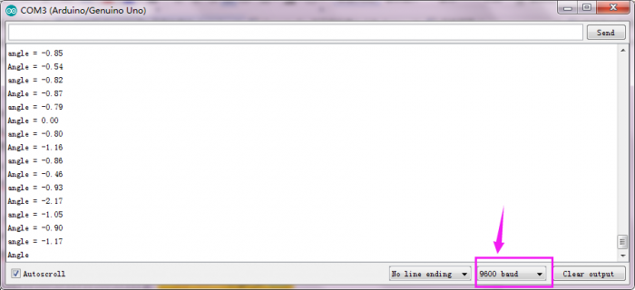
Project 11: Speed Loop Adjustment
Description:
We have introduced before that can adjust the angle to balance the car on the almost horizontal ground by controlling the PD.
However, if subjected to external forces or on a slope, the car can't keep balance because there is an error in speed. So you need to adjust the speed of the car for balancing.
Therefore, a speed measuring module is required.
The motor we used comes with a Hall encoder for speed measurement.
Based on the previous lesson, add a PI (proportional and integral) control to adjust the speed. In this way, it is possible to control the car to be balanced even if it is on a slope.
The speed loop here is positive feedback, which means that if the car is going backwards, then the car will move forward at a faster speed.
To be specific, if gently push the car with hand, the wheel of the car accelerates in the direction of pushing, that is, the direction in which the car is tilted, so that the tilt angle of the car is reversed in the opposite direction, that is, contrary to the direction of pushing;
the car will accelerate in the direction of tilting, and the speed is accelerated.
The PI adjustment of speed just offsets the previously generated dip angle, and returns to near the initial equilibrium point without falling.
Principle and function of PI regulation:
Adjust the speed with the proportional parameter (kp_speed), so that the car can quickly approach the required speed;
Adjust the accumulated value of the speed error with the integral parameter (ki_speed) to eliminate the static error.
For example:
Supposed that there is a water vat, ensure that the water level in the vat is maintained at a height of 1 meter forever.
Suppose the initial water level is 0.2 meter, then there is an error between the current water level and the target water level, and the error is 0.8m.
At this time, you want to control the water level by adding water.
If simply use the Proportional control algorithm, the amount of water added (u) is proportional to the error. That is, u=kp*error
Supposed kp=0.5, t=1 (add water in the first time), so u=0.5*0.8=0.4 , should add the water quantity of 0.4m; now the current water level should be 0.2m+0.4m=0.6m
Then t=2 (add water in the second time), this time water level 0.6m, error 0.4m, so should add the water quantity u=0.5*0.4=0.2 ; now the current water level should be 0.6m+0.2m=0.8m
Followed by this calculation. The water level will reach 1m.
But there are some shortcomings in such single proportional control, one of which is – steady state error!
Like the above example, depending on the value of kp, the system will eventually reach 1 meter without steady state error.
However, considering another situation, suppose that there is water leakage in the process of adding water to the water tank. It is assumed that the water of 0.1 m height will be missed every time the water is added.
Supposed kp=0.5, after several times of adding water, the water level in the water tank will reach 0.8m, the water level will not change again! Because the water level is 0.8m, the error =1-0.8=0.2m.
Therefore, the amount of water added to the water tank is u=0.5*0.2=0.1m.
At the same time, 0.1m of water will flow out from the water tank every time. The added water offsets the leaked water, so the water level will not change!
In other words, the target water level is 1m, but finally the water system reaches 0.8m and not changes. The system has reached stability. The resulting error is the steady-state error.
Therefore, separate proportional control does not meet the requirements in many cases. So we need integral control algorithm.
From the above example, you can find that if only use proportional control, may exist the Transient error, so the water level will be only 0.8m.
In control, we introduce a component that is proportional to the integral of the error.
Therefore, the proportional + integral control algorithm is:
u=kp*error+ ki∗∫error
Here we still use the example mentioned above.
The error of the first time is 0.8, and error of the second time is 0.4. At this point, the integral of the error (in the case of discrete, the integral is actually accumulating), ∫error=0.8+0.4=1.2. The amount of control at this time, in addition to a part of proportion, another part is a coefficient ki multiplied by this integral term.
Since this integral term will accumulate the previous errors, the steady-state error can be well eliminated.
(assuming that in the case of only proportional terms, the system is stuck in the steady-state error, i.e. 0.8 in the above example. Due to the addition of the integral term, input will increase so that the water level of the tank can be greater than 0.8 and gradually reach the target's 1.0.)
This is the function of integral term.
Source Code:
#include <MsTimer2.h>        //internal timer 2
#include <PinChangeInt.h>    //This library file can make all pins on the REV4 board as external interrupts.
#include <MPU6050.h>      //MPU6050 library
#include <Wire.h>        //IIC library

MPU6050 mpu6050;     //Instantiate an MPU6050 object; name mpu6050
int16_t ax, ay, az, gx, gy, gz;     // Define three-axis acceleration, three-axis gyroscope variables

//TB6612 pins
const int right_R1=8;
const int right_R2=12;
const int PWM_R=10;
const int left_L1=7;
const int left_L2=6;
const int PWM_L=9;

///////////////////////angle parameters//////////////////////////////
float angle_X; //Calculate the tilt angle variable about the X axis from the acceleration
float angle_Y; //Calculate the tilt angle variable about the Y axis from the acceleration
float angle0 = 1; //Actual measured angle (ideally 0 degrees)
float Gyro_x,Gyro_y,Gyro_z;  //Angular angular velocity by gyroscope calculation
///////////////////////angle parameters//////////////////////////////

///////////////////////Kalman_Filter////////////////////////////
float Q_angle = 0.001;  //Covariance of gyroscope noise
float Q_gyro = 0.003;    //Covariance of gyroscope drift noise
float R_angle = 0.5;    //Covariance of accelerometer
char C_0 = 1;
float dt = 0.005; // The value of dt is the filter sampling time.
float K1 = 0.05; //a function containing the Kalman gain is used to calculate the deviation of the optimal estimate
float K_0,K_1,t_0,t_1;
float angle_err;
float q_bias;    //Gyro drift

float accelz = 0;
float angle;
float angleY_one;
float angle_speed;

float Pdot[4] = { 0, 0, 0, 0};
float P[2][2] = {{ 1, 0 }, { 0, 1 }};
float  PCt_0, PCt_1, E;
//////////////////////Kalman_Filter/////////////////////////

//////////////////////PID parameters///////////////////////////////
double kp = 34, ki = 0, kd = 0.62;                   //angle loop parameters
double kp_speed = 3.6, ki_speed = 0.080, kd_speed = 0;   // speed loop parameters
double setp0 = 0; //angle balance point
int PD_pwm;  //angle output
float pwm1=0,pwm2=0;

//////////////////Interrupt speed measurement/////////////////////////////
#define PinA_left 5  //external interrupts
#define PinA_right 4   //external interrupts
volatile long count_right = 0;//Used to calculate the pulse value calculated by the Hall encoder (the volatile long type is to ensure the value is valid)
volatile long count_left = 0;
int speedcc = 0;
//////////////////////pulse calculation/////////////////////////
int lz = 0;
int rz = 0;
int rpluse = 0;
int lpluse = 0;
int pulseright,pulseleft;
////////////////////////////////PI variable parameters//////////////////////////
float speeds_filterold=0;
float positions=0;
int flag1;
double PI_pwm;
int cc;
int speedout;
float speeds_filter;

void setup()
{
  // set the pins of motor to OUTPUT
  pinMode(right_R1,OUTPUT);
  pinMode(right_R2,OUTPUT);
  pinMode(left_L1,OUTPUT);
  pinMode(left_L2,OUTPUT);
  pinMode(PWM_R,OUTPUT);
  pinMode(PWM_L,OUTPUT);

  //assign initial state value
  digitalWrite(right_R1,1);
  digitalWrite(right_R2,0);
  digitalWrite(left_L1,0);
  digitalWrite(left_L2,1);
  analogWrite(PWM_R,0);
  analogWrite(PWM_L,0);

  pinMode(PinA_left, INPUT);  //speed code wheel input
  pinMode(PinA_right, INPUT);

  // join I2C bus
  Wire.begin();                            //join I2C bus sequence
  Serial.begin(9600);                       //open the serial monitor to set the baud rate to 9600
  delay(1500);
  mpu6050.initialize();                       //initialize MPU6050
  delay(2);

  //5ms; use timer2 to set timer interruption (note:using timer2 will affect the PWM output of pin3 pin11)
  MsTimer2::set(5, DSzhongduan);    //5ms ; execute the function DSzhongduan once
  MsTimer2::start();    //start interrupt
}

void loop()
{
  Serial.println(angle);
  delay(100);
  //Serial.println(PD_pwm);
  //Serial.println(pwm1);
  //Serial.println(pwm2);
  //Serial.print("pulseright = ");
  //Serial.println(pulseright);
  //Serial.print("pulseleft = ");
  //Serial.println(pulseleft);
  //Serial.println(PI_pwm);
  //Serial.println(speeds_filter);
  //Serial.println (positions);

  //External interrupt for calculating wheel speed
  attachPinChangeInterrupt(PinA_left, Code_left, CHANGE);          //PinA_left Level change triggers external interrupt; execute subfunction Code_left
  attachPinChangeInterrupt(PinA_right, Code_right, CHANGE);       //PinA_right Level change triggers external interrupt; execute subfunction Code_right
}

/////////////////////Hall calculation/////////////////////////
//left speed code wheel count
void Code_left()
{
  count_left ++;
}
//Right speed code wheel count
void Code_right()
{
  count_right ++;
}
////////////////////pulse calculation///////////////////////
void countpluse()
{
  lz = count_left;     //Assign the value counted by the code wheel to lz
  rz = count_right;

  count_left = 0;     //Clear the code counter count
  count_right = 0;

  lpluse = lz;
  rpluse = rz;

  if ((pwm1 < 0) && (pwm2 < 0))                     //judge the moving direction; if backwards(PWM, namely motor voltage is negative), pulse number is a negative number
  {
    rpluse = -rpluse;
    lpluse = -lpluse;
  }
  else if ((pwm1 > 0) && (pwm2 > 0))                 // if backwards(PWM, namely motor voltage is positive), pulse number is a positive number
  {
    rpluse = rpluse;
    lpluse = lpluse;
  }
  else if ((pwm1 < 0) && (pwm2 > 0))                 //Judge turning direction of the car;  turn left; Right pulse number is a positive number; Left pulse number is a negative number.
  {
    rpluse = rpluse;
    lpluse = -lpluse;
  }
  else if ((pwm1 > 0) && (pwm2 < 0))               //Judge turning direction of the car;  turn right; Right pulse number is a negative number; Left pulse number is a positive number.
  {
    rpluse = -rpluse;
    lpluse = lpluse;
  }

  //enter interrupts per 5ms; pulse number superposes
  pulseright += rpluse;
  pulseleft += lpluse;
}

/////////////////////////////////interrupts////////////////////////////
void DSzhongduan()
{
  sei();  //Allow global interrupts
  countpluse();        //Pulse superposition subfunction
  mpu6050.getMotion6(&ax, &ay, &az, &gx, &gy, &gz);     //IIC to get MPU6050 six-axis data  ax ay az gx gy gz
  angle_calculate(ax, ay, az, gx, gy, gz, dt, Q_angle, Q_gyro, R_angle, C_0, K1);      //get angle and Kalman filtering
  PD();         //angle loop PD control
  anglePWM();

  cc++;
  if(cc>=8)     //5*8=40,40ms entering once speed PI algorithm
  {
    speedpiout();
    cc=0;  //Clear
  }
}
///////////////////////////////////////////////////////////

/////////////////////////////angle calculation///////////////////////
void angle_calculate(int16_t ax,int16_t ay,int16_t az,int16_t gx,int16_t gy,int16_t gz,float dt,float Q_angle,float Q_gyro,float R_angle,float C_0,float K1)
{
  float Angle = -atan2(ay , az) * (180/ PI);           //Radial rotation angle calculation formula; negative sign is direction processing
  Gyro_x = -gx / 131;              //The X-axis angular velocity calculated by the gyroscope; the negative sign is the direction processing
  Kalman_Filter(Angle, Gyro_x);            //Kalman Filtering
  //Rotation angle Z-axis parameter
  Gyro_z = -gz / 131;                      //Z-axis angular velocity
  //accelz = az / 16.4;

  float angleAx = -atan2(ax, az) * (180 / PI); //Calculate the angle with the x-axis
  Gyro_y = -gy / 131.00; //Y-axis angular velocity
  Yiorderfilter(angleAx, Gyro_y); //first-order filtering
}
////////////////////////////////////////////////////////////////

///////////////////////////////KalmanFilter/////////////////////
void Kalman_Filter(double angle_m, double gyro_m)
{
  angle += (gyro_m - q_bias) * dt;          //Prior estimate
  angle_err = angle_m - angle;

  Pdot[0] = Q_angle - P[0][1] - P[1][0];    //Differential of azimuth error covariance
  Pdot[1] = - P[1][1];
  Pdot[2] = - P[1][1];
  Pdot[3] = Q_gyro;

  P[0][0] += Pdot[0] * dt;    //A priori estimation error covariance differential integral
  P[0][1] += Pdot[1] * dt;
  P[1][0] += Pdot[2] * dt;
  P[1][1] += Pdot[3] * dt;

  //Intermediate variable of matrix multiplication
  PCt_0 = C_0 * P[0][0];
  PCt_1 = C_0 * P[1][0];
  //Denominator
  E = R_angle + C_0 * PCt_0;
  //gain value
  K_0 = PCt_0 / E;
  K_1 = PCt_1 / E;

  t_0 = PCt_0;  //Intermediate variable of matrix multiplication
  t_1 = C_0 * P[0][1];

  P[0][0] -= K_0 * t_0;    //Posterior estimation error covariance
  P[0][1] -= K_0 * t_1;
  P[1][0] -= K_1 * t_0;
  P[1][1] -= K_1 * t_1;

  q_bias += K_1 * angle_err;    //Posterior estimate
  angle_speed = gyro_m - q_bias;   //The differential of the output value gives the optimal angular velocity
  angle += K_0 * angle_err; ////Posterior estimation to get the optimal angle
}

/////////////////////first-order filtering/////////////////
void Yiorderfilter(float angle_m, float gyro_m)
{
  angleY_one = K1 * angle_m + (1 - K1) * (angleY_one + gyro_m * dt);
}

//////////////////angle PD////////////////////
void PD()
{
  PD_pwm = kp * (angle + angle0) + kd * angle_speed; //PD angle loop control
}

//////////////////speed PI////////////////////
void speedpiout()
{
  float speeds = (pulseleft + pulseright) * 1.0;      //Vehicle speed  pulse value
  pulseright = pulseleft = 0;      //Clear
  speeds_filterold *= 0.7;         //first-order complementary filtering
  speeds_filter = speeds_filterold + speeds * 0.3;
  speeds_filterold = speeds_filter;
  positions += speeds_filter;
  positions = constrain(positions, -3550,3550);    //Anti-integral saturation
  PI_pwm = ki_speed * (setp0 - positions) + kp_speed * (setp0 - speeds_filter);      //speed loop control PI
}
//////////////////speed PI////////////////////


////////////////////////////PWM end value/////////////////////////////
void anglePWM()
{
  pwm2=-PD_pwm - PI_pwm ;           //assign the final value of PWM to motor
  pwm1=-PD_pwm - PI_pwm ;

  if(pwm1>255)             //limit PWM value not greater than 255
  {
    pwm1=255;
  }
  if(pwm1<-255)
  {
    pwm1=-255;
  }
  if(pwm2>255)
  {
    pwm2=255;
  }
  if(pwm2<-255)
  {
    pwm2=-255;
  }

  if(angle>80 || angle<-80)      // the inclined angle of balance car is greater than 45°, motor will stop.
  {
    pwm1=pwm2=0;
  }

 if(pwm2>=0)         // determine the motor’s steering and speed according to the positive and negative of PWM
  {
    digitalWrite(left_L1,LOW);
    digitalWrite(left_L2,HIGH);
    analogWrite(PWM_L,pwm2);
  }
  else
  {
    digitalWrite(left_L1,HIGH);
    digitalWrite(left_L2,LOW);
    analogWrite(PWM_L,-pwm2);
  }

  if(pwm1>=0)
  {
    digitalWrite(right_R1,LOW);
    digitalWrite(right_R2,HIGH);
    analogWrite(PWM_R,pwm1);
  }
  else
  {
    digitalWrite(right_R1,HIGH);
    digitalWrite(right_R2,LOW);
    analogWrite(PWM_R,-pwm1);
  }
}
Test Result
Installed well the balance car, upload the source code and power on; turn the power switch ON.
The balance car will stand upright on the desktop.
Then open the Arduino IDE, set the baud rate to 9600, the serial monitor will pop up the inclined value of balance car.
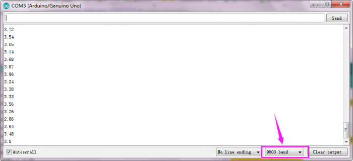
Remove the USB cable and balance the car upright on the ground.
If you push it gently by hand, the car will advance in the direction you push, but the tilt angle of the car is opposite to the direction of the push, so the car will return to the balance point without falling.
Project 12: Steering Loop Control
Description:
The steering of the car also needs to be adjusted by the PD.
The balance robot is driven by the left and right motor speed difference to eliminate the deviation from the center of the road.
By adjusting the direction of the balancing robot and adding the balancing robot to the forward motion, the distance difference between the balancing robot and the center line can be gradually eliminated.
This process is a proportional P process, so the differential control of balance robot generally only needs simple proportional control to complete the direction control.
However, since the robot car itself is equipped with a relatively heavy object such as a battery, it has a large moment of inertia. It may occurs steering overshoot phenomenon during the adjustment process. If it is not suppressed, the balance robot will oversteer and fall down.
According to the experience of angle and speed control mentioned above, in order to eliminate the overshoot in the direction control of balance robot, it is necessary to increase the angle differential D control.

Project 13: Bluetooth Control
Description:
In the above projects, you have learned how to balance the robot upright; how to use the Bluetooth APP to control the balancing robot.
In this project, let’s move on to combine these two functions. To begin with, control the balance robot stand upright; then make the robot move in different directions using Android Bluetooth control.
However, due to the errors caused by the installation and the mpu6050, there may be a phenomenon that go fast and easily fall down or slow to turn back or can’t move. The solution please refer to the project 12 and the second section mentioned below.
Notice:
The balance shield comes with a slide switch for Bluetooth communication. When upload the code for testing, must turn the switch OFF; or else, uploading fails.
When connect to Bluetooth module, should turn the switch ON.
Source Code:
Note: Before test the source code, do remember to add the corresponding library.
You can refer to the method in the link:
https://wiki.keyestudio.com/How_to_Install_Arduino_Library
#include <MsTimer2.h>        //internal timer 2
#include <PinChangeInt.h>    //this library can make all pins of arduino REV4 as external interrupt
#include <MPU6050.h>      //MPU6050 library
#include <Wire.h>        //IIC communication library

MPU6050 mpu6050;     //Instantiate an MPU6050 object; name mpu6050
int16_t ax, ay, az, gx, gy, gz;     //Define three-axis acceleration, three-axis gyroscope variables

//TB6612 pins
const int right_R1=8;
const int right_R2=12;
const int PWM_R=10;
const int left_L1=7;
const int left_L2=6;
const int PWM_L=9;

///////////////////////angle parameters//////////////////////////////
float angle_X; //calculate the inclined angle variable of X-axis by accelerometer
float angle_Y; //calculate the inclined angle variable of Y-axis by accelerometer
float angle0 = 1; //Actual measured angle (ideally 0 degrees)
float Gyro_x,Gyro_y,Gyro_z;  //Angular angular velocity for gyroscope calculation
///////////////////////angle parameters//////////////////////////////

///////////////////////Kalman_Filter////////////////////////////
float Q_angle = 0.001;  //Covariance of gyroscope noise
float Q_gyro = 0.003;    //Covariance of gyroscope drift noise
float R_angle = 0.5;    //Covariance of accelerometer
char C_0 = 1;
float dt = 0.005; //The value of dt is the filter sampling time
float K1 = 0.05; //  a function containing the Kalman gain; used to calculate the deviation of the optimal estimate
float K_0,K_1,t_0,t_1;
float angle_err;
float q_bias;    //gyroscope drift

float accelz = 0;
float angle;
float angleY_one;
float angle_speed;

float Pdot[4] = { 0, 0, 0, 0};
float P[2][2] = {{ 1, 0 }, { 0, 1 }};
float  PCt_0, PCt_1, E;
//////////////////////Kalman_Filter/////////////////////////

//////////////////////PID parameters///////////////////////////////
double kp = 34, ki = 0, kd = 0.62;                   //angle loop parameters
double kp_speed = 3.6, ki_speed = 0.080, kd_speed = 0;   // speed loop parameters
double kp_turn = 24, ki_turn = 0, kd_turn = 0.08;       // steering loop parameters
double setp0 = 0; //Angle balance point
int PD_pwm;  //angle output
float pwm1=0,pwm2=0;

//////////////////Interrupt speed count/////////////////////////////
#define PinA_left 5  //external interrupt
#define PinA_right 4   //external interrupt
volatile long count_right = 0;//Used to calculate the pulse value calculated by the Hall encoder (the volatile long type is to ensure the value is valid)
volatile long count_left = 0;
int speedcc = 0;
//////////////////////pulse count/////////////////////////
int lz = 0;
int rz = 0;
int rpluse = 0;
int lpluse = 0;
int pulseright,pulseleft;
////////////////////////////////PI variable parameter//////////////////////////
float speeds_filterold=0;
float positions=0;
int flag1;
double PI_pwm;
int cc;
int speedout;
float speeds_filter;

//////////////////////////////steering PD///////////////////
int turnmax,turnmin,turnout;
float Turn_pwm = 0;
int zz=0;
int turncc=0;

//Bluetooth//
int front = 0;//go front variable
int back = 0;//go back variable
int left = 0;//turn left
int right = 0;//turn right
char val;

void setup()
{
  //set the motor control pins to OUTPUT
  pinMode(right_R1,OUTPUT);
  pinMode(right_R2,OUTPUT);
  pinMode(left_L1,OUTPUT);
  pinMode(left_L2,OUTPUT);
  pinMode(PWM_R,OUTPUT);
  pinMode(PWM_L,OUTPUT);

  //assign initial state value
  digitalWrite(right_R1,1);
  digitalWrite(right_R2,0);
  digitalWrite(left_L1,0);
  digitalWrite(left_L2,1);
  analogWrite(PWM_R,0);
  analogWrite(PWM_L,0);

  pinMode(PinA_left, INPUT);  //Speed encoder input
  pinMode(PinA_right, INPUT);

  // join I2C bus
  Wire.begin();                            //join I2C bus sequence
  Serial.begin(9600);                       //open the serial monitor and set the baud rate to 9600
  delay(1500);
  mpu6050.initialize();                       //initialize MPU6050
  delay(2);

  //5ms; use timer2 to set timer interruption (note:using timer2 will affect the PWM output of pin3 pin11)
  MsTimer2::set(5, DSzhongduan);    //5ms ; execute the function DSzhongduan once
  MsTimer2::start();    //start interrupt
}

void loop()
{
  Serial.print(angle_speed);
  Serial.print("     ");
  Serial.println(Gyro_x);

  //Serial.println(angle);
  //delay(100);
  //Serial.println(PD_pwm);
  //Serial.println(pwm1);
  //Serial.println(pwm2);
  //Serial.print("pulseright = ");
  //Serial.println(pulseright);
  //Serial.print("pulseleft = ");
  //Serial.println(pulseleft);
  //Serial.println(PI_pwm);
  //Serial.println(speeds_filter);
  //Serial.println (positions);
  //Serial.println(Turn_pwm);
  //Serial.println(Gyro_z);
  //Serial.println(Turn_pwm);


  if(Serial.available())
  {
    val = Serial.read();      //assign the value read from serial port to val
    //Serial.println(val);
    switch(val)             //switch statement
    {
      case 'F': front=250; break;       //if val equals to F,front=250,balance robot goes front.
      case 'B': back=-250; break;       //go back
      case 'L': left=1; break;    //turn left
      case 'R': right=1; break;                         // turn right
      case 'S': front=0,back=0,left=0,right=0;break;    //stop
      case 'D': Serial.print(angle);break;    //when receiving ‘D’,send value of angle to APP
    }
  }

  //external interrupt; used to calculate the wheel speed
  attachPinChangeInterrupt(PinA_left, Code_left, CHANGE);          //PinA_left  Level change triggers external interrupt;  execute subfunction Code_left
  attachPinChangeInterrupt(PinA_right, Code_right, CHANGE);       //PinA_right Level change triggers external interrupt;  execute subfunction Code_right
}

/////////////////////Hall count/////////////////////////
//left speed encoder count
void Code_left()
{
  count_left ++;
}
//right speed encoder count
void Code_right()
{
  count_right ++;
}
////////////////////pulse count///////////////////////
void countpluse()
{
  lz = count_left;     //assign the value counted by encoder to lz
  rz = count_right;

  count_left = 0;     //clear the count quantity
  count_right = 0;

  lpluse = lz;
  rpluse = rz;

  if ((pwm1 < 0) && (pwm2 < 0))                     //judge the moving direction of balance robot; if go back (PWM the motor voltage is negative), the number of pulses is negative.
  {
    rpluse = -rpluse;
    lpluse = -lpluse;
  }
  else if ((pwm1 > 0) && (pwm2 > 0))                 // if go back (PWM the motor voltage is positive) , the number of pulses is positive.
  {
    rpluse = rpluse;
    lpluse = lpluse;
  }
  else if ((pwm1 < 0) && (pwm2 > 0))                 //judge the moving direction of balance robot; if turn left, right pulse is positive but left pulse is negative.
  {
    rpluse = rpluse;
    lpluse = -lpluse;
  }
  else if ((pwm1 > 0) && (pwm2 < 0))               //judge the moving direction of balance robot; if turn right , right pulse is negative but left pulse is positive.
  {
    rpluse = -rpluse;
    lpluse = lpluse;
  }

  //entering interrupt per 5ms,pulse will plus
  pulseright += rpluse;
  pulseleft += lpluse;
}

/////////////////////////////////interrupt ////////////////////////////
void DSzhongduan()
{
  sei();  //allow overall interrupt
  countpluse();        //pulse count subfunction
  mpu6050.getMotion6(&ax, &ay, &az, &gx, &gy, &gz);     //IIC to get MPU6050 six-axis data ax ay az gx gy gz
  angle_calculate(ax, ay, az, gx, gy, gz, dt, Q_angle, Q_gyro, R_angle, C_0, K1);      //get the angle and Kalman filtering
  PD();         //PD control of angle loop
  anglePWM();

  cc++;
  if(cc>=8)     //5*8=40,40ms entering PI count of speed once
  {
    speedpiout();
    cc=0;  // Clear
  }
  turncc++;
  if(turncc>4)       //20ms entering PI count of steering once
  {
    turnspin();
    turncc=0;     //Clear
  }
}
///////////////////////////////////////////////////////////

/////////////////////////////tilt angle calculation///////////////////////
void angle_calculate(int16_t ax,int16_t ay,int16_t az,int16_t gx,int16_t gy,int16_t gz,float dt,float Q_angle,float Q_gyro,float R_angle,float C_0,float K1)
{
  float Angle = -atan2(ay , az) * (180/ PI);           //Radial rotation angle calculation formula; the negative sign is direction processing.
  Gyro_x = -gx / 131;              //The X-axis angular velocity calculated by the gyroscope ; the negative sign is the direction processing.
  Kalman_Filter(Angle, Gyro_x);            // Kalman Filter
  // Z-axis angular velocity
  Gyro_z = -gz / 131;                      //speed of Z-axis
  //accelz = az / 16.4;

  float angleAx = -atan2(ax, az) * (180 / PI); //calculate the included angle of X-axis
  Gyro_y = -gy / 131.00; //angle speed of Y-axis
  Yiorderfilter(angleAx, Gyro_y); //first-order filtering
}
////////////////////////////////////////////////////////////////

///////////////////////////////KalmanFilter/////////////////////
void Kalman_Filter(double angle_m, double gyro_m)
{
  angle += (gyro_m - q_bias) * dt;          //prior estimate
  angle_err = angle_m - angle;

  Pdot[0] = Q_angle - P[0][1] - P[1][0];    //The differential of the covariance of the prior estimate error
  Pdot[1] = - P[1][1];
  Pdot[2] = - P[1][1];
  Pdot[3] = Q_gyro;

  P[0][0] += Pdot[0] * dt;    //The integral of the covariance differential of the prior estimate error
  P[0][1] += Pdot[1] * dt;
  P[1][0] += Pdot[2] * dt;
  P[1][1] += Pdot[3] * dt;

  //Intermediate variables in matrix multiplication
  PCt_0 = C_0 * P[0][0];
  PCt_1 = C_0 * P[1][0];
  //denominator
  E = R_angle + C_0 * PCt_0;
  //gain value
  K_0 = PCt_0 / E;
  K_1 = PCt_1 / E;

  t_0 = PCt_0;  //Intermediate variables in matrix multiplication
  t_1 = C_0 * P[0][1];

  P[0][0] -= K_0 * t_0;    //the covariance of the prior estimate error
  P[0][1] -= K_0 * t_1;
  P[1][0] -= K_1 * t_0;
  P[1][1] -= K_1 * t_1;

  q_bias += K_1 * angle_err;    //posterior estimate
  angle_speed = gyro_m - q_bias;   //The differential of the output value; get the optimal angular velocity
  angle += K_0 * angle_err; ////posterior estimate; get the optimal angular velocity
}

/////////////////////first-order filtering/////////////////
void Yiorderfilter(float angle_m, float gyro_m)
{
  angleY_one = K1 * angle_m + (1 - K1) * (angleY_one + gyro_m * dt);
}

//////////////////angle PD////////////////////
void PD()
{
  PD_pwm = kp * (angle + angle0) + kd * angle_speed; //PD angle loop control
}

//////////////////speed PI////////////////////
void speedpiout()
{
  float speeds = (pulseleft + pulseright) * 1.0;      //pulse value of speed
  pulseright = pulseleft = 0;      //Clear
  speeds_filterold *= 0.7;         //first-order complementary filtering
  speeds_filter = speeds_filterold + speeds * 0.3;
  speeds_filterold = speeds_filter;
  positions += speeds_filter;
  positions += front;             //Forward control fusion
  positions += back;              //backward control fusion
  positions = constrain(positions, -3550,3550);    //Anti-integral saturation
  PI_pwm = ki_speed * (setp0 - positions) + kp_speed * (setp0 - speeds_filter);      //speed loop controlling PI
}
//////////////////speed PI////////////////////

///////////////////////////steering/////////////////////////////////
void turnspin()
{
  int flag = 0;      //
  float turnspeed = 0;
  float rotationratio = 0;

  if (left == 1 || right == 1)
  {
    if (flag == 0)                             //judge the speed before turning; increase the car’s flexibility.
    {
      turnspeed = ( pulseright + pulseleft);                      //current speed of car; pulse expression
      flag=1;
    }
    if (turnspeed < 0)                                 //Absolute value of the car's current speed
    {
      turnspeed = -turnspeed;
    }
    if(left==1||right==1)         //if press left key or right key
    {
     turnmax=3;          //maximum value of turning
     turnmin=-3;         // minimum value of turning
    }
    rotationratio = 5 / turnspeed;          //set the value by speed
    if (rotationratio < 0.5)
    {
      rotationratio = 0.5;
    }

    if (rotationratio > 5)
    {
      rotationratio = 5;
    }
  }
  else
  {
    rotationratio = 0.5;
    flag = 0;
    turnspeed = 0;
  }
  if (left ==1)//plus by direction parameter
  {
    turnout += rotationratio;
  }
  else if (right == 1 )//plus by direction parameter
  {
    turnout -= rotationratio;
  }
  else turnout = 0;
  if (turnout > turnmax)   turnout = turnmax;//the max value setting of amplitude
  if (turnout < turnmin)   turnout = turnmin;//the min value setting of amplitude

  Turn_pwm = -turnout * kp_turn - Gyro_z * kd_turn;//The rotation PD algorithm controls the fusion speed and Z axis rotation positioning
}
///////////////////////////turning/////////////////////////////////

////////////////////////////PWM end value/////////////////////////////
void anglePWM()
{
  pwm2=-PD_pwm - PI_pwm + Turn_pwm;           //assign the end value of PWM to motor
  pwm1=-PD_pwm - PI_pwm - Turn_pwm;

  if(pwm1>255)             //limit the PWM value not more than 255
  {
    pwm1=255;
  }
  if(pwm1<-255)
  {
    pwm1=-255;
  }
  if(pwm2>255)
  {
    pwm2=255;
  }
  if(pwm2<-255)
  {
    pwm2=-255;
  }

  if(angle>80 || angle<-80)      //if tilt angle is greater than 45° , motor will stop.
  {
    pwm1=pwm2=0;
  }

 if(pwm2>=0)         //motor’s turning and speed are determined by the positive or negative of PWM
  {
    digitalWrite(left_L1,LOW);
    digitalWrite(left_L2,HIGH);
    analogWrite(PWM_L,pwm2);
  }
  else
  {
    digitalWrite(left_L1,HIGH);
    digitalWrite(left_L2,LOW);
    analogWrite(PWM_L,-pwm2);
  }

  if(pwm1>=0)
  {
    digitalWrite(right_R1,LOW);
    digitalWrite(right_R2,HIGH);
    analogWrite(PWM_R,pwm1);
  }
  else
  {
    digitalWrite(right_R1,HIGH);
    digitalWrite(right_R2,LOW);
    analogWrite(PWM_R,-pwm1);
  }
}
Use Method:
- 1)installed well the balance robot, upload the test code;
- 2)pull out the USB cable, then turn the power control switch of shield ON.
- 3)the balance shield comes with a Bluetooth switch; then turn the switch ON.
Refer to the project 6 on how to connect the Bluetooth module.
- 4)Open the APP to connect Bluetooth; if Bluetooth connected, place the balance robot on the ground to make it stand upright.
Then tap the Button key ![]() , you can control the robot go front, back, turn left or turn right by tapping the direction arrow icon.
, you can control the robot go front, back, turn left or turn right by tapping the direction arrow icon.
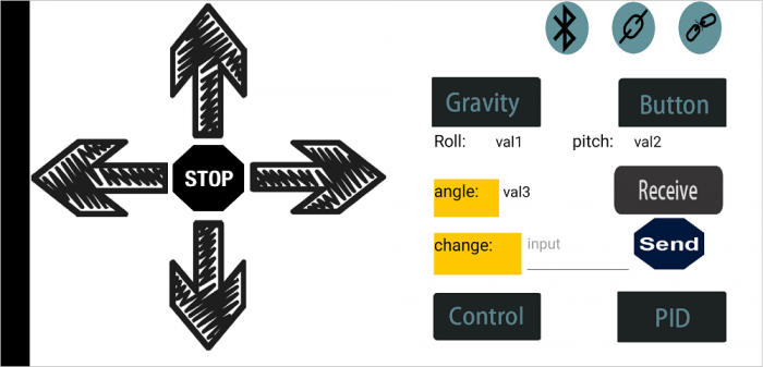
- 5)press the key
 ,you can also control the robot moving by gravity sensing system( must carried by your phone).
Adjusting Balance Angle and PID by Bluetooth APP
Description:
In the previous projects, we were able to control the car's upright balance and movement.
However, due to the error caused by the car installation and the mpu6050, the mechanical balance angle of the car is not perpendicular to the horizontal plane.
Thus when using Bluetooth controls the car’s forward or backward, its tilt angle is small and the wheel is almost motionless or moves slowly.
When controlling the car’s backward or forward, its tilt angle is very large and the wheel speed is very fast, so it is likely to accelerate over a certain distance and fall down.
In order to reduce these errors, we can adjust the mechanical balance angle and the main parameters of the PID through the mobile APP.
How to use the Bluetooth APP?
1) follow the method mentioned before to upload the code to control the balance car move.
2) set the tilt angle. When controlling the balance car, the front and rear speed of the car are not the same, so there is a deviation.
Then click the key ![]() , get a tilt angle. Shown below.
, get a tilt angle. Shown below.
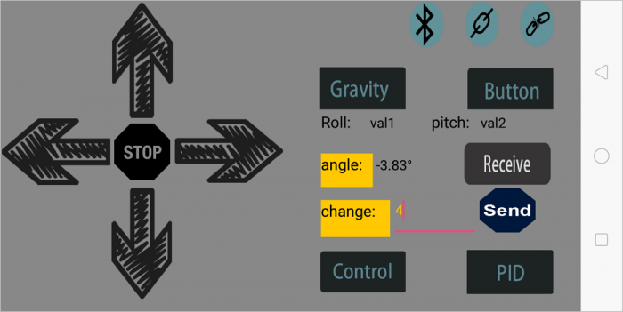
If get a negative number, type a positive number on the change bar![]() , so that the negative number plus the positive number equals to nearly 0.
, so that the negative number plus the positive number equals to nearly 0.
Then click the key ![]() , control the balance car move and observe the moving state.
, control the balance car move and observe the moving state.
3) You can also press the PID ![]() on the Bluetooth APP,to set the PID parameters,then tap other keys to adjust the PID parameters, making the balance robot stable.
on the Bluetooth APP,to set the PID parameters,then tap other keys to adjust the PID parameters, making the balance robot stable.
Or refer to the moving state of balance car under different parameters.
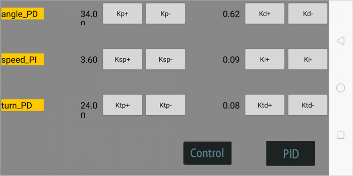
Settings finished, press the key![]() to return to the control interface.
to return to the control interface.
Source Code:
Note: Before test the source code, do remember to add the corresponding library.
You can refer to the method in the link:
https://wiki.keyestudio.com/How_to_Install_Arduino_Library
#include <MsTimer2.h>        //internal timer 2
#include <PinChangeInt.h>    //this library can make all pins of arduino REV4 as external interrupt
#include <MPU6050.h>      //MPU6050 library
#include <Wire.h>        //IIC communication library

MPU6050 mpu6050;     //Instantiate an MPU6050 object; name mpu6050
int16_t ax, ay, az, gx, gy, gz;     //Define three-axis acceleration, three-axis gyroscope variables

//TB6612 pins
const int right_R1=8;
const int right_R2=12;
const int PWM_R=10;
const int left_L1=7;
const int left_L2=6;
const int PWM_L=9;

///////////////////////angle parameters//////////////////////////////
float angle_X; //calculate the inclined angle variable of X-axis by accelerometer
float angle_Y; //calculate the inclined angle variable of Y-axis by accelerometer
int angle0 = 0; //Actual measured angle (ideally 0 degrees)
float Gyro_x,Gyro_y,Gyro_z;  //Angular angular velocity for gyroscope calculation
///////////////////////angle parameters//////////////////////////////

///////////////////////Kalman_Filter////////////////////////////
float Q_angle = 0.001;  //Covariance of gyroscope noise
float Q_gyro = 0.003;    //Covariance of gyroscope drift noise
float R_angle = 0.5;    //Covariance of accelerometer
char C_0 = 1;
float dt = 0.005; //The value of dt is the filter sampling time
float K1 = 0.05; // a function containing the Kalman gain; used to calculate the deviation of the optimal estimate
float K_0,K_1,t_0,t_1;
float angle_err;
float q_bias;    //gyroscope drift

float accelz = 0;
float angle;
float angleY_one;
float angle_speed;

float Pdot[4] = { 0, 0, 0, 0};
float P[2][2] = {{ 1, 0 }, { 0, 1 }};
float  PCt_0, PCt_1, E;
//////////////////////Kalman_Filter/////////////////////////

//////////////////////PID parameters///////////////////////////////
double kp = 34.00, ki = 0, kd = 0.62;                   //angle loop parameter
double kp_speed = 3.60, ki_speed = 0.08, kd_speed = 0;   // speed loop parameter
double kp_turn = 24.00, ki_turn = 0, kd_turn = 0.08;                 // steering loop parameter
double setp0 = 0; //angle balance point
int PD_pwm;  //angle output
float pwm1=0,pwm2=0;

//////////////////interrupt speed count/////////////////////////////
#define PinA_left 5  //external interrupt
#define PinA_right 4   //external interrupt
volatile long count_right = 0;//Used to calculate the pulse value calculated by the Hall encoder (the volatile long type is to ensure that the value is valid)
volatile long count_left = 0;
int speedcc = 0;
//////////////////////pulse count/////////////////////////
int lz = 0;
int rz = 0;
int rpluse = 0;
int lpluse = 0;
int pulseright,pulseleft;
////////////////////////////////PI variable parameter//////////////////////////
float speeds_filterold=0;
float positions=0;
int flag1;
double PI_pwm;
int cc;
int speedout;
float speeds_filter;

//////////////////////////////steering PD///////////////////
int turnmax,turnmin,turnout;
float Turn_pwm = 0;
int zz=0;
int turncc=0;

//Bluetooth//
int front = 0;//backward variable
int back = 0;//forward variable
int left = 0;//turn left
int right = 0;//turn right
char val;

int TT;

void setup()
{
  //set the control pins of motor to OUTPUT
  pinMode(right_R1,OUTPUT);
  pinMode(right_R2,OUTPUT);
  pinMode(left_L1,OUTPUT);
  pinMode(left_L2,OUTPUT);
  pinMode(PWM_R,OUTPUT);
  pinMode(PWM_L,OUTPUT);

  //assign the initial value
  digitalWrite(right_R1,1);
  digitalWrite(right_R2,0);
  digitalWrite(left_L1,0);
  digitalWrite(left_L2,1);
  analogWrite(PWM_R,0);
  analogWrite(PWM_L,0);

  pinMode(PinA_left, INPUT);  //speed encoder input
  pinMode(PinA_right, INPUT);

  // join I2C bus
  Wire.begin();                            //join I2C bus sequence
  Serial.begin(9600);                       //open the serial monitor, set the baud rate to 9600
  delay(1500);
  mpu6050.initialize();                       //initialize MPU6050
  delay(2);

  //5ms; use timer2 to set timer interruption (note:using timer2 will affect the PWM output of pin3 pin11)
  MsTimer2::set(5, DSzhongduan);    //5ms;  execute the function DSzhongduan once
  MsTimer2::start();    //start interrupt
}

void loop()
{
  //Serial.println(angle);
  //delay(100);
  //Serial.println(PD_pwm);
  //Serial.println(pwm1);
  //Serial.println(pwm2);
  //Serial.print("pulseright = ");
  //Serial.println(pulseright);
  //Serial.print("pulseleft = ");
  //Serial.println(pulseleft);
  //Serial.println(PI_pwm);
  //Serial.println(speeds_filter);
  //Serial.println (positions);
  //Serial.println(Turn_pwm);
  //Serial.println(Gyro_z);
  //Serial.println(Turn_pwm);


  if(Serial.available())
  {
    val = Serial.read();      //assign the value read from serial port to val
    //Serial.println(val);
    switch(val)             //switch statement
    {
      case 'F': front=250; break;       //if vale equals F,front=250,go front
      case 'B': back=-250; break;       //go back
      case 'L': left=1; break;    //turn left
      case 'R': right=1; break;                         //turn right
      case 'S': front=0,back=0,left=0,right=0;break;    //stop
      case 'Q': Serial.print(angle);break;    //receiving‘D’,send the value of variable angle to APP
      case 'P': kp=kp+0.5,Serial.print(kp);break;
      case 'O': kp=kp-0.5,Serial.print(kp);break;
      case 'I': kd=kd+0.02,Serial.print(kd);break;
      case 'U': kd=kd-0.02,Serial.print(kd);break;
      case 'Y': kp_speed=kp_speed+0.05,Serial.print(kp_speed);break;
      case 'T': kp_speed=kp_speed-0.05,Serial.print(kp_speed);break;
      case 'G': ki_speed=ki_speed+0.01,Serial.print(ki_speed);break;
      case 'H': ki_speed=ki_speed-0.01,Serial.print(ki_speed);break;
      case 'J': kp_turn=kp_turn+0.4,Serial.print(kp_turn);break;
      case 'K': kp_turn=kp_turn-0.4,Serial.print(kp_turn);break;
      case 'N': kd_turn=kd_turn+0.01,Serial.print(kd_turn);break;
      case 'M': kd_turn=kd_turn-0.01,Serial.print(kd_turn);break;
    }
    if(val=='F'||val=='B'||val=='L'||val=='R'||val=='S'||val=='Q'||val=='P'||val=='O'||val=='I'||val=='U'||val=='Y'||val=='T'||val=='G'||val=='H'||val=='J'||val=='K'||val=='N'||val=='M')
    {
      TT = angle0;
    }
    else
    {
      TT = val;
      angle0=TT;
    }
    //Serial.println(angle0);

  }

  //external interrupt; used to calculate the wheel speed
  attachPinChangeInterrupt(PinA_left, Code_left, CHANGE);          //PinA_left Level change triggers external interrupt; execute subfunction Code_left
  attachPinChangeInterrupt(PinA_right, Code_right, CHANGE);       //PinA_right Level change triggers external interrupt; execute Code_right
}

/////////////////////Hall count/////////////////////////
//left speed encoder count
void Code_left()
{
  count_left ++;
}
//right speed encoder count
void Code_right()
{
  count_right ++;
}
////////////////////pulse count///////////////////////
void countpluse()
{
  lz = count_left;     //assign the value counted by encoder to lz
  rz = count_right;

  count_left = 0;     //Clear the count quantity
  count_right = 0;

  lpluse = lz;
  rpluse = rz;

  if ((pwm1 < 0) && (pwm2 < 0))                     //judge the car’s moving direction; if backward (PWM /motor voltage is negative), pulse is a negative number.
  {
    rpluse = -rpluse;
    lpluse = -lpluse;
  }
  else if ((pwm1 > 0) && (pwm2 > 0))                 //if backward (PWM /motor voltage is positive), pulse is a positive number.
  {
    rpluse = rpluse;
    lpluse = lpluse;
  }
  else if ((pwm1 < 0) && (pwm2 > 0))                 //judge the car’s moving direction; if turn left, the right pulse is positive; left pulse is negative.
  {
    rpluse = rpluse;
    lpluse = -lpluse;
  }
  else if ((pwm1 > 0) && (pwm2 < 0))               //judge the car’s moving direction; if turn right, the right pulse is negative ; left pulse is positive.
  {
    rpluse = -rpluse;
    lpluse = lpluse;
  }

  //entering interrupt per,pulse plus
  pulseright += rpluse;
  pulseleft += lpluse;
}

/////////////////////////////////interrupt////////////////////////////
void DSzhongduan()
{
  sei();  //allow overall interrupt
  countpluse();        //pulse plus subfunction
  mpu6050.getMotion6(&ax, &ay, &az, &gx, &gy, &gz);     //IIC to get MPU6050 six-axis data ax ay az gx gy gz
  angle_calculate(ax, ay, az, gx, gy, gz, dt, Q_angle, Q_gyro, R_angle, C_0, K1);      //get angle and Kalman filtering
  PD();         // PD control of angle loop
  anglePWM();

  cc++;
  if(cc>=8)     //5*8=40,that is, execute the PI calculation of speed once per 40ms
  {
    speedpiout();
    cc=0;  //Clear
  }
  turncc++;
  if(turncc>4)       //20ms, that is, execute the PD calculation of steering once per 40ms
  {
    turnspin();
    turncc=0;     //Clear
  }
}
///////////////////////////////////////////////////////////

/////////////////////////////tilt angle calculation ///////////////////////
void angle_calculate(int16_t ax,int16_t ay,int16_t az,int16_t gx,int16_t gy,int16_t gz,float dt,float Q_angle,float Q_gyro,float R_angle,float C_0,float K1)
{
  float Angle = -atan2(ay , az) * (180/ PI);           //Radial rotation angle calculation formula ; negative sign is direction processing
  Gyro_x = -gx / 131;              //The X-axis angular velocity calculated by the gyroscope ; the negative sign is the direction processing
  Kalman_Filter(Angle, Gyro_x);            //Kalman Filter
  //Rotation angle Z-axis parameter
  Gyro_z = -gz / 131;                      //angle speed of Z-axis
  //accelz = az / 16.4;

  float angleAx = -atan2(ax, az) * (180 / PI); //calculate the inclined angle of X-axis
  Gyro_y = -gy / 131.00; //angle speed of Y-axis
  Yiorderfilter(angleAx, Gyro_y); //first-order filtering
}
////////////////////////////////////////////////////////////////

///////////////////////////////KalmanFilter/////////////////////
void Kalman_Filter(double angle_m, double gyro_m)
{
  angle += (gyro_m - q_bias) * dt;          //prior estimate
  angle_err = angle_m - angle;

  Pdot[0] = Q_angle - P[0][1] - P[1][0];    //The differential of the covariance of the prior estimate error
  Pdot[1] = - P[1][1];
  Pdot[2] = - P[1][1];
  Pdot[3] = Q_gyro;

  P[0][0] += Pdot[0] * dt;    //A priori estimation error covariance differential integral
  P[0][1] += Pdot[1] * dt;
  P[1][0] += Pdot[2] * dt;
  P[1][1] += Pdot[3] * dt;

  //Intermediate variables in matrix multiplication
  PCt_0 = C_0 * P[0][0];
  PCt_1 = C_0 * P[1][0];
  //denominator
  E = R_angle + C_0 * PCt_0;
  //gain value
  K_0 = PCt_0 / E;
  K_1 = PCt_1 / E;

  t_0 = PCt_0;  //Intermediate variables in matrix multiplication
  t_1 = C_0 * P[0][1];

  P[0][0] -= K_0 * t_0;    //Posterior estimation error covariance
  P[0][1] -= K_0 * t_1;
  P[1][0] -= K_1 * t_0;
  P[1][1] -= K_1 * t_1;

  q_bias += K_1 * angle_err;    //Posterior estimate
  angle_speed = gyro_m - q_bias;   //The differential of the output value; get the optimal angular velocity
  angle += K_0 * angle_err; ////Posterior estimation; get the optimal angle
}

/////////////////////first-order filtering/////////////////
void Yiorderfilter(float angle_m, float gyro_m)
{
  angleY_one = K1 * angle_m + (1 - K1) * (angleY_one + gyro_m * dt);
}

//////////////////angle PD////////////////////
void PD()
{
  PD_pwm = kp * (angle + angle0) + kd * angle_speed; //PD angle loop control
}

//////////////////speed PI////////////////////
void speedpiout()
{
  float speeds = (pulseleft + pulseright) * 1.0;      //speed; pulse value
  pulseright = pulseleft = 0;      //Clear
  speeds_filterold *= 0.7;         //first-order complementary filtering
  speeds_filter = speeds_filterold + speeds * 0.3;
  speeds_filterold = speeds_filter;
  positions += speeds_filter;
  positions += front;             //Forward control fusion
  positions += back;              //Backward control fusion
  positions = constrain(positions, -3550,3550);    //Anti-integral saturation
  PI_pwm = ki_speed * (setp0 - positions) + kp_speed * (setp0 - speeds_filter);      //speed loop control PI
}
//////////////////speed PI////////////////////

///////////////////////////turning/////////////////////////////////
void turnspin()
{
  int flag = 0;      //
  float turnspeed = 0;
  float rotationratio = 0;

  if (left == 1 || right == 1)
  {
    if (flag == 0)                             //judge the current speed before turning, to increase the flexibility.
    {
      turnspeed = ( pulseright + pulseleft);                      //current speed; pulse expression
      flag=1;
    }
    if (turnspeed < 0)                                 //absolute value of current speed
    {
      turnspeed = -turnspeed;
    }
    if(left==1||right==1)         //if press the left key or right key
    {
     turnmax=5;          //the maximum value of turning
     turnmin=-5;         //the minimum value of turning
    }
    rotationratio = 5 / turnspeed;          //set by the speed of car
    if (rotationratio < 0.5)
    {
      rotationratio = 0.5;
    }

    if (rotationratio > 5)
    {
      rotationratio = 5;
    }
  }
  else
  {
    rotationratio = 0.5;
    flag = 0;
    turnspeed = 0;
  }
  if (left ==1)//add according to orientation parameter
  {
    turnout += rotationratio;
  }
  else if (right == 1 )//add according to orientation parameter
  {
    turnout -= rotationratio;
  }
  else turnout = 0;
  if (turnout > turnmax)   turnout = turnmax;//the max value setting of amplitude
  if (turnout < turnmin)   turnout = turnmin;//the min value setting of amplitude

  Turn_pwm = -turnout * kp_turn - Gyro_z * kd_turn;//The rotation PD algorithm controls the fusion speed and Z axis rotation positioning
}
///////////////////////////steering/////////////////////////////////

////////////////////////////PWM end value/////////////////////////////
void anglePWM()
{
  pwm2=-PD_pwm - PI_pwm + Turn_pwm;           //assign the end value of PWM to motor
  pwm1=-PD_pwm - PI_pwm - Turn_pwm;

  if(pwm1>255)             //limit PWM value not more than 255
  {
    pwm1=255;
  }
  if(pwm1<-255)
  {
    pwm1=-255;
  }
  if(pwm2>255)
  {
    pwm2=255;
  }
  if(pwm2<-255)
  {
    pwm2=-255;
  }

  if(angle>80 || angle<-80)      // if the tilt angle is greater than 45°,motor will stop turning.
  {
    pwm1=pwm2=0;
  }

 if(pwm2>=0)         //determine the motor’s turning and speed by the negative and positive of PWM
  {
    digitalWrite(left_L1,LOW);
    digitalWrite(left_L2,HIGH);
    analogWrite(PWM_L,pwm2);
  }
  else
  {
    digitalWrite(left_L1,HIGH);
    digitalWrite(left_L2,LOW);
    analogWrite(PWM_L,-pwm2);
  }

  if(pwm1>=0)
  {
    digitalWrite(right_R1,LOW);
    digitalWrite(right_R2,HIGH);
    analogWrite(PWM_R,pwm1);
  }
  else
  {
    digitalWrite(right_R1,HIGH);
    digitalWrite(right_R2,LOW);
    analogWrite(PWM_R,-pwm1);
  }
}
Project 14: Adjusting Balance Angle and Bluetooth Control
Description:
In the above project, we first connect the Bluetooth and then adjust the balancing angle of car on the Bluetooth APP.
Now, we first adjust the balancing angle of car by hand; then connect the Android Bluetooth to control the car moving via Bluetooth APP.
Notice:
- 1)Thew balance shield comes with a slide switch for Bluetooth communication. When upload the code for testing, must turn the switch OFF; or else, uploading fails.
When connect to Bluetooth module, should turn the switch ON.
- 2)Using the source code of this project, can only adjust once each time starting up; must adjust the angle first, or else the car can’t keep balance.
Source Code:
Note:Before test the source code, do remember to add the corresponding library.
You can refer to the method in the link:
https://wiki.keyestudio.com/How_to_Install_Arduino_Library
#include <MsTimer2.h>        //Internal timer2
#include <PinChangeInt.h>    //This library file can make all pins on the REV4 board as external interrupts.  Define three-axis acceleration, three-axis gyroscope variables
#include <MPU6050.h>      //MPU6050 Library
#include <Wire.h>        //IIC communication library

MPU6050 mpu6050;     // Instantiate an MPU6050 object; name mpu6050
int16_t ax, ay, az, gx, gy, gz;     //Define three-axis acceleration, three-axis gyroscope variables

//TB6612 pins definition
const int right_R1=8;
const int right_R2=12;
const int PWM_R=10;
const int left_L1=7;
const int left_L2=6;
const int PWM_L=9;

const int buz = 11;
const int btn = 13;

///////////////////////angle parameters//////////////////////////////
float angle_X; // calculate the inclined angle variable of X-axis by accelerometer
float angle_Y; //calculate the inclined angle variable of Y-axis by accelerometer
float angle0 = 0; //mechanical balance angle (ideally 0 degrees)
float Gyro_x,Gyro_y,Gyro_z;  //Angular angular velocity by gyroscope calculation
///////////////////////angle parameter//////////////////////////////

///////////////////////Kalman_Filter////////////////////////////
float Q_angle = 0.001;  //Covariance of gyroscope noise
float Q_gyro = 0.003;    // Covariance of gyroscope drift noise
float R_angle = 0.5;    //Covariance of accelerometer
char C_0 = 1;
float dt = 0.005; //The value of dt is the filter sampling time
float K1 = 0.05; // a function containing the Kalman gain is used to calculate the deviation of the optimal estimate
float K_0,K_1,t_0,t_1;
float angle_err;
float q_bias;    //gyroscope drift

float accelz = 0;
float angle;
float angleY_one;
float angle_speed;

float Pdot[4] = { 0, 0, 0, 0};
float P[2][2] = {{ 1, 0 }, { 0, 1 }};
float  PCt_0, PCt_1, E;
//////////////////////Kalman_Filter/////////////////////////

//////////////////////PID parameter///////////////////////////////
double kp = 34, ki = 0, kd = 0.62;                   //angle loop parameter
double kp_speed = 3.56, ki_speed = 0.072, kd_speed = 0;   // speed loop parameter
double kp_turn = 24, ki_turn = 0, kd_turn = 0.08;                 // steering loop parameter
double setp0 = 0; //angle balance point
int PD_pwm;  //angle output
float pwm1=0,pwm2=0;

//////////////////interrupt speed count/////////////////////////////
#define PinA_left 5  //external interrupt
#define PinA_right 4   //external interrupt
volatile long count_right = 0;//Used to calculate the pulse value calculated by the Hall encoder (the volatile long type is to ensure the value is valid)
volatile long count_left = 0;
int speedcc = 0;
//////////////////////pulse count/////////////////////////
int lz = 0;
int rz = 0;
int rpluse = 0;
int lpluse = 0;
int pulseright,pulseleft;
////////////////////////////////PI variable parameter//////////////////////////
float speeds_filterold=0;
float positions=0;
int flag1;
double PI_pwm;
int cc;
int speedout;
float speeds_filter;

//////////////////////////////turning PD///////////////////
int turnmax,turnmin,turnout;
float Turn_pwm = 0;
int zz=0;
int turncc=0;

//Bluetooth//
int front = 0;//forward variable
int back = 0;//backward
int left = 0;//turn left
int right = 0;//turn right
char val;

int i,button;

void setup()
{
  //set the motor control pins to OUTPUT
  pinMode(right_R1,OUTPUT);
  pinMode(right_R2,OUTPUT);
  pinMode(left_L1,OUTPUT);
  pinMode(left_L2,OUTPUT);
  pinMode(PWM_R,OUTPUT);
  pinMode(PWM_L,OUTPUT);

  //assign the initial state value
  digitalWrite(right_R1,1);
  digitalWrite(right_R2,0);
  digitalWrite(left_L1,0);
  digitalWrite(left_L2,1);
  analogWrite(PWM_R,0);
  analogWrite(PWM_L,0);

  pinMode(PinA_left, INPUT);  //speed encoder input
  pinMode(PinA_right, INPUT);

  pinMode(btn,INPUT);
  pinMode(buz,OUTPUT);

  // join I2C bus
  Wire.begin();                            //join I2C bus sequence
  Serial.begin(9600);                       //open the serial monitor and set the baud rate to 9600
  delay(1500);
  mpu6050.initialize();                       //initialize MPU6050
  delay(2);

  //5ms; use timer2 to set the timer interrupt (note: using timer2 may affects the PWM output of pin3 pin11)
  MsTimer2::set(5, DSzhongduan);    //5ms; execute the function DSzhongduan once
  MsTimer2::start();    //start interrupt
}

 //buzzer
void buzzer()
{
    for(int i=0;i<50;i++)
    {
    digitalWrite(buz,HIGH);
    delay(1);
    digitalWrite(buz,LOW);
    delay(1);
    }
    delay(50);
    for(int i=0;i<50;i++)
    {
    digitalWrite(buz,HIGH);
    delay(1);
    digitalWrite(buz,LOW);
    delay(1);
    }
}

void loop()
{
  //Serial.println(angle0);
  //Serial.print("angle= ");
  //Serial.println(angle);
  //delay(1);
  //Serial.println(PD_pwm);
  //Serial.println(pwm1);
  //Serial.println(pwm2);
  //Serial.print("pulseright = ");
  //Serial.println(pulseright);
  //Serial.print("pulseleft = ");
  //Serial.println(pulseleft);
  //Serial.println(PI_pwm);
  //Serial.println(speeds_filter);
  //Serial.println (positions);
  //Serial.println(Turn_pwm);
  //Serial.println(Gyro_z);
  //Serial.println(Turn_pwm);

  while(i<1)
  {
    button = digitalRead(btn);
    if(button == 0)
    {
      angle0=-angle;
      //Serial.println(angle0);
      buzzer();
      i++;
    }
  }
  if(Serial.available())
  {
    val = Serial.read();      //assign the value read from the serial port to val
    //Serial.println(val);
    switch(val)             //switch statement
    {
      case 'F': front=250; break;       //if val equals F,front=250,car will move forward
      case 'B': back=-250; break;       //go back
      case 'L': left=1; break;    //turn left
      case 'R': right=1; break;                         //turn right
      case 'S': front=0,back=0,left=0,right=0;break;    //stop
      case 'D': Serial.print(angle);break;
    }
  }

  //external interrupt; used to calculate the wheel speed
  attachPinChangeInterrupt(PinA_left, Code_left, CHANGE);          //PinA_left Level change triggers the external interrupt; execute the subfunction Code_left
  attachPinChangeInterrupt(PinA_right, Code_right, CHANGE);       //PinA_right Level change triggers the external interrupt; execute the subfunction Code_right
}

/////////////////////Hall count/////////////////////////
//left speed encoder count
void Code_left()
{
  count_left ++;
}
//right speed encoder count
void Code_right()
{
  count_right ++;
}
////////////////////pulse count///////////////////////
void countpluse()
{
  lz = count_left;     //assign the value counted by encoder to lz
  rz = count_right;

  count_left = 0;     //Clear count quantity
  count_right = 0;

  lpluse = lz;
  rpluse = rz;

  if ((pwm1 < 0) && (pwm2 < 0))                     //judge the car’s moving direction; if backward (PWM namely motor voltage is negative), pulse is a negative number.
  {
    rpluse = -rpluse;
    lpluse = -lpluse;
  }
  else if ((pwm1 > 0) && (pwm2 > 0))                 //if backward (PWM namely motor voltage is positive), pulse is a positive number.
  {
    rpluse = rpluse;
    lpluse = lpluse;
  }
  else if ((pwm1 < 0) && (pwm2 > 0))                 //judge the car’s moving direction; if turn left, right pulse is a positive number; left pulse is a negative number.
  {
    rpluse = rpluse;
    lpluse = -lpluse;
  }
  else if ((pwm1 > 0) && (pwm2 < 0))               //judge the car’s moving direction; if turn right, right pulse is a negative number; left pulse is a positive number.
  {
    rpluse = -rpluse;
    lpluse = lpluse;
  }

  // enter interrupt per 5ms,pulse number plus
  pulseright += rpluse;
  pulseleft += lpluse;
}

/////////////////////////////////interrupt ////////////////////////////
void DSzhongduan()
{
  sei();  //allow overall interrupt
  countpluse();        //pulse plus subfunction
  mpu6050.getMotion6(&ax, &ay, &az, &gx, &gy, &gz);     //IIC to get MPU6050 six-axis data  ax ay az gx gy gz
  angle_calculate(ax, ay, az, gx, gy, gz, dt, Q_angle, Q_gyro, R_angle, C_0, K1);      //get angle and Kalmam filtering
  PD();         //angle loop PD control
  anglePWM();

  cc++;
  if(cc>=8)     //5*8=40,enter PI algorithm of speed per 40ms
  {
    speedpiout();
    cc=0;  //Clear
  }
  turncc++;
  if(turncc>4)       //20ms; enter PD algorithm of steering
  {
    turnspin();
    turncc=0;     //Clear
  }
}
///////////////////////////////////////////////////////////

/////////////////////////////tilt calculation///////////////////////
void angle_calculate(int16_t ax,int16_t ay,int16_t az,int16_t gx,int16_t gy,int16_t gz,float dt,float Q_angle,float Q_gyro,float R_angle,float C_0,float K1)
{
  float Angle = -atan2(ay , az) * (180/ PI);           //Radial rotation angle calculation formula ; negative sign is direction processing
  Gyro_x = -gx / 131;              //The X-axis angular velocity calculated by the gyroscope;  the negative sign is the direction processing
  Kalman_Filter(Angle, Gyro_x);            //Kalman Filter
  //rotating angle Z-axis parameter
  Gyro_z = -gz / 131;                      //angle speed of Z-axis
  //accelz = az / 1604;

  float angleAx = -atan2(ax, az) * (180 / PI); //calculate the inclined angle with x-axis
  Gyro_y = -gy / 131.00; //angle speed of Y-axis
  Yiorderfilter(angleAx, Gyro_y); //first-order filtering
}
////////////////////////////////////////////////////////////////

///////////////////////////////KalmanFilter/////////////////////
void Kalman_Filter(double angle_m, double gyro_m)
{
  angle += (gyro_m - q_bias) * dt;          //prior estimate
  angle_err = angle_m - angle;

  Pdot[0] = Q_angle - P[0][1] - P[1][0];    //The differential of the covariance of the prior estimate error
  Pdot[1] = - P[1][1];
  Pdot[2] = - P[1][1];
  Pdot[3] = Q_gyro;

  P[0][0] += Pdot[0] * dt;    //The integral of the covariance differential of the prior estimate error
  P[0][1] += Pdot[1] * dt;
  P[1][0] += Pdot[2] * dt;
  P[1][1] += Pdot[3] * dt;

  //Intermediate variables in matrix multiplication
  PCt_0 = C_0 * P[0][0];
  PCt_1 = C_0 * P[1][0];
  //denominator
  E = R_angle + C_0 * PCt_0;
  //gain value
  K_0 = PCt_0 / E;
  K_1 = PCt_1 / E;

  t_0 = PCt_0;  //Intermediate variables in matrix multiplication
  t_1 = C_0 * P[0][1];

  P[0][0] -= K_0 * t_0;    //Posterior estimation error covariance
  P[0][1] -= K_0 * t_1;
  P[1][0] -= K_1 * t_0;
  P[1][1] -= K_1 * t_1;

  q_bias += K_1 * angle_err;    //Posterior estimate
  angle_speed = gyro_m - q_bias;   //The differential of the output value gives the optimal angular velocity
  angle += K_0 * angle_err; ////Posterior estimation; get the optimal angle
}

/////////////////////first-order filter/////////////////
void Yiorderfilter(float angle_m, float gyro_m)
{
  angleY_one = K1 * angle_m + (1 - K1) * (angleY_one + gyro_m * dt);
}

//////////////////angle PD////////////////////
void PD()
{
  PD_pwm = kp * (angle + angle0) + kd * angle_speed; //PD angle loop control
}

//////////////////speed PI////////////////////
void speedpiout()
{
  float speeds = (pulseleft + pulseright) * 1.0;      //speed  pulse value
  pulseright = pulseleft = 0;      //clear
  speeds_filterold *= 0.7;         //first-order complementary filtering
  speeds_filter = speeds_filterold + speeds * 0.3;
  speeds_filterold = speeds_filter;
  positions += speeds_filter;
  positions += front;             //Forward control fusion
  positions += back;              //backward control fusion
  positions = constrain(positions, -3550,3550);    //Anti-integral saturation
  PI_pwm = ki_speed * (setp0 - positions) + kp_speed * (setp0 - speeds_filter);      //speed loop control PI
}
//////////////////speed PI////////////////////

///////////////////////////turning/////////////////////////////////
void turnspin()
{
  int flag = 0;      //
  float turnspeed = 0;
  float rotationratio = 0;

  if (left == 1 || right == 1)
  {
    if (flag == 0)                             //judge the speed before rotate, to increase the flexibility
    {
      turnspeed = ( pulseright + pulseleft);                      //current speed ; express in pulse
      flag=1;
    }
    if (turnspeed < 0)                                 //speed absolute value
    {
      turnspeed = -turnspeed;
    }
    if(left==1||right==1)         //if press left key or right key
    {
     turnmax=3;          //max turning value
     turnmin=-3;         //min turning value
    }
    rotationratio = 5 / turnspeed;          //speed setting value
    if (rotationratio < 0.5)
    {
      rotationratio = 0.5;
    }

    if (rotationratio > 5)
    {
      rotationratio = 5;
    }
  }
  else
  {
    rotationratio = 0.5;
    flag = 0;
    turnspeed = 0;
  }
  if (left ==1)//plus according to direction parameter
  {
    turnout += rotationratio;
  }
  else if (right == 1 )//plus according to direction parameter
  {
    turnout -= rotationratio;
  }
  else turnout = 0;
  if (turnout > turnmax)   turnout = turnmax;//max value of amplitude
  if (turnout < turnmin)   turnout = turnmin;//min value of amplitude

  Turn_pwm = -turnout * kp_turn - Gyro_z * kd_turn;//turning PD algorithm control
}
///////////////////////////turning/////////////////////////////////

////////////////////////////PWM end value/////////////////////////////
void anglePWM()
{
  pwm2=-PD_pwm - PI_pwm + Turn_pwm;           //assign the end value of PWM to motor
  pwm1=-PD_pwm - PI_pwm - Turn_pwm;

  if(pwm1>255)             //limit PWM value not greater than255
  {
    pwm1=255;
  }
  if(pwm1<-255)
  {
    pwm1=-255;
  }
  if(pwm2>255)
  {
    pwm2=255;
  }
  if(pwm2<-255)
  {
    pwm2=-255;
  }

  if(angle>45 || angle<-45)      //if tilt angle is greater than 45°,motor will stop
  {
    pwm1=pwm2=0;
  }

   if(pwm2>=0)         //determine the motor steering and speed by negative and positive of PWM
  {
    digitalWrite(left_L1,LOW);
    digitalWrite(left_L2,HIGH);
    analogWrite(PWM_L,pwm2);
  }
  else
  {
    digitalWrite(left_L1,HIGH);
    digitalWrite(left_L2,LOW);
    analogWrite(PWM_L,-pwm2);
  }

  if(pwm1>=0)
  {
    digitalWrite(right_R1,LOW);
    digitalWrite(right_R2,HIGH);
    analogWrite(PWM_R,pwm1);
  }
  else
  {
    digitalWrite(right_R1,HIGH);
    digitalWrite(right_R2,LOW);
    analogWrite(PWM_R,-pwm1);
  }
}
How to use ?
1)installed well the balance robot, upload the test code;
2)pull out the USB cable, then turn the power control switch of shield ON. Keep the car balance; when the motor rotates, press the button key 13, and buzzer will make a “tick”. In this case, the car is adjusted well.
3)follow the Bluetooth control methods mentioned above; connect the Bluetooth module to make the balance robot run using APP.
Refer to the project 6 on how to connect the Bluetooth module.
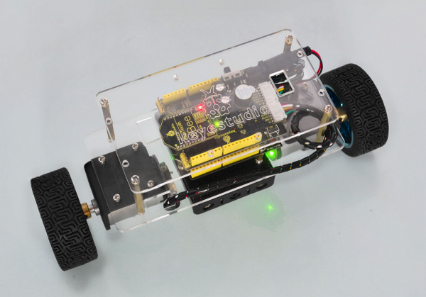
Resource
https://fs.keyestudio.com/KS0193
Get One Now
