Ks0142 keyestudio SIM900 GSM/GPRS Module Shield: Difference between revisions
Keyestudio (talk | contribs) No edit summary |
Keyestudio (talk | contribs) |
||
| (51 intermediate revisions by the same user not shown) | |||
| Line 1: | Line 1: | ||
<br>[[File: | [[image:1421.png|thumb|400px|right|Keyestudio SIM900 GSM/GPRS Module Shield]] | ||
<br> | |||
==Introduction== | |||
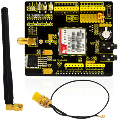
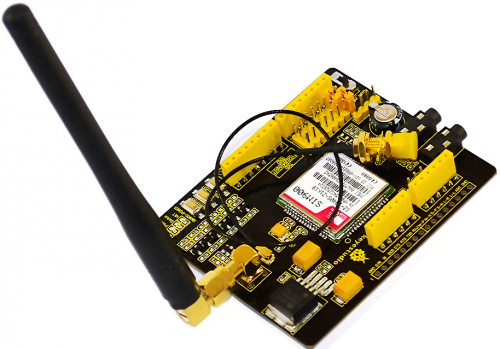
SIM900 GSM/GPRS shield is based on Quad-Band SIM900 GSM/GPRS module. It provides Arduino with GSM/GPRS function. <br> | |||
This shield allows you to make voice calls, send SMS or make connections to the Internet network.<br> | |||
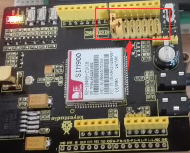
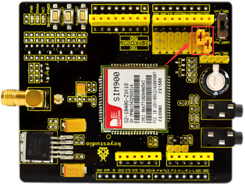
On the shield, there is a serial port toggle switch for you to select either software serial port or hardware serial port to be connected to GPRS Shield. <br> | |||
If you choose software serial port, you need to use the Software UART; otherwise, you need to use the Hardware UART. <br> | |||
The shield includes a high capacitor dedicated to RTC (Real Time Clock).<br> | |||
If you toggle the switch to DBG-Port, you can connect the port to Arduino or connect the port to PC by Arduino to proceed the debugging. <br> | |||
<br> | |||
==Specification== | |||
'''1.''' Auto-adaption to 3.3V and 5V main board, supporting 3.3V platforms such as leaf maple and Chip kit;<br> | |||
'''2.''' After connecting the SIM900 shield to Arduino, 9V/2A DC power supply is needed. Otherwise, there might be malfunction;<br> | |||
'''3.''' Quad-Band GSM/GPRS 850/900/1800/1900MHz (Support 2G card of UNICOM, China Mobile, do not support Telecom card). <br> | |||
We use SIM900 GSM Module – supporting communication in 900MHz band. <br> | |||
You should check the mobile network band in your area. <br> | |||
<br> | |||
==Shield Details== | |||
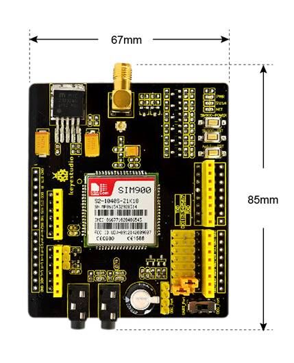
* Dimensions: 67mm x 85mm x 21mm | |||
* Weight: 35.7g | |||
<br>[[File:KS0142 Detail.jpg|500px|frameless|thumb]]<br> | |||
== | <br> | ||
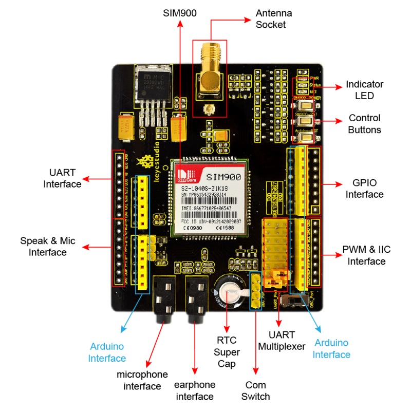
==PINOUT Explanation== | |||
<br>[[File:KS0142 pinout.jpg|800px|frameless|thumb]]<br> | |||
<br> | |||
==Using Method== | |||
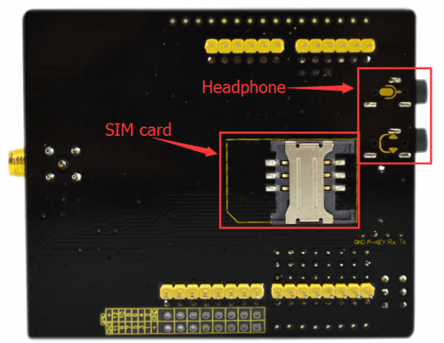
1. Insert the SIM Card into the SIM Card slot. | |||
<br>[[File:ks0142.png|500px|frameless|thumb]]<br> | |||
<br> | |||
2. Make sure the antenna pad is buckled properly. If you don’t want to fix it on the board, a patch cord is also supplied with the GPRS Shield to interface the antenna to the board. At the same time, plug your headphone into the shield. | |||
<br>[[File:ks0142-2.png|500px|frameless|thumb]]<br> | |||
<br> | |||
3. Then, connect UNO R3 to computer using a USB cable, and upload the code to the board. | |||
<br>[[File:ks0142-3.png|500px|frameless|thumb]]<br> | |||
<br> | |||
4. UNO R3 communicates with GPRS module by serial port, so after uploading (you must plug the shield into UNO R3 after uploading the code, or serial port can’t work.), connect RXD(D0) on UNO R3 to TXD on the shield, TXD(D1)to RXD on the shield.<br> | |||
<br> | |||
5. <span style="color: red">''' Note that:''' </span> If you need more serial ports, except for the default serial port D0 and D1, you can add some by programming. <br> | |||
We provide the code to make RXD(D6) and TXD(D7) serial ports below.<br> | |||
<br>[[File:ks0142-4.png|500px|frameless|thumb]]<br> | |||
<br> | |||
6. Because in the program, you can set set the number you want to dial. After uploading and connecting, press dialing key and you can make a voice call by the headphone with a mobile phone. | |||
<br> | |||
==Test Code== | |||
=== 1) For default serial ports RXD(D0) and TXD(D1):call up === | |||
<pre> | |||
void setup() | |||
{ | |||
pinMode(13, OUTPUT); | |||
pinMode(9, OUTPUT); //D9 is SIM900 turn on pin | |||
digitalWrite(9,HIGH); | |||
delay(1000); | |||
digitalWrite(9,LOW); | |||
delay(15000); | |||
Serial.begin(9600); | |||
} | |||
void loop() | |||
{ | |||
Serial.print("ATD15812345678;\r");//15812345678 your dialing phone number | |||
delay(100000); | |||
// Serial.println("ATH"); | |||
delay(200000); | |||
} | |||
</pre> | |||
<br> | |||
<span style="color: red">''' Code to Note:'''<br> | |||
In the code '''Serial.print("ATD15812345678;\r")''', here you can change the phone number you want to dial.<br> | |||
<br> | |||
'''Test Result'''<br> | |||
Done uploading the code, connect the earphone and SIM card to the shield, and connect the antenna. Shown below.<br> | |||
Then stack the shield onto UNO R3 board, slide the toggle switch to the UART side, powered on, wait for about 2 minutes, it will dial the number that you have set well in the code. After calling, you can talk through the earphone.<br> | |||
<br>[[File:KS0142 Result.png|800px|frameless|thumb]]<br> | |||
<br>[[File:0142 (5).jpg|800px|frameless|thumb]]<br> | |||
<br> | |||
===2) For adding serial ports RXD(D0) and TXD(D1): send text=== | |||
<pre> | |||
void sendMeg() | |||
{ | |||
Serial.println("AT"); | |||
delay(2000); | |||
Serial.println("AT+CMGF=1"); | |||
delay(2000); | |||
Serial.println("AT+CMGS=\"15812345678\"");//change into your phone number | |||
delay(2000); | |||
Serial.print("ABCDEFGHIJKLMN\r\n");//write the content here | |||
delay(2000); | |||
Serial.write(0x1A); | |||
} | |||
void setup() { | |||
// put your setup code here, to run once: | |||
Serial.begin(9600); | |||
} | |||
void loop() { | |||
// put your main code here, to run repeatedly: | |||
delay(15*1000); | |||
sendMeg(); | |||
} | |||
</pre> | |||
<br> | |||
<span style="color: red">''' Code to Note:''' <br> | |||
'''1.''' Serial.println("AT+CMGS=\"15812345678\"");//change into your phone number<br> | |||
'''2.''' Serial.print("ABCDEFGHIJKLMN\r\n");//write the content here | |||
<br> | |||
'''Test Result:'''<br> | |||
Done uploading the code, insert the SIM card into SIM900 GSM/GPRS shield, and then install the antenna, as well as stack the shield onto UNO R3 board.<br> | |||
Power the UNO R3 board, the PWR LED on the shield lights; long press the SIM900-POWER button, waiting the Stable LED and NET LED light up; release the SIM900-POWER button, wait for a minute, your phone will receive the message sent from SIM900. | |||
<br>[[File:图片.jpg|400px|frameless|thumb]]<br> | |||
<br> | |||
== | ===3) For adding serial ports RXD(D6) and TXD(D7): call up=== | ||
<pre> | |||
#include <SoftwareSerial.h> | |||
SoftwareSerial SIM900(6, 7); // define serial port PIN | |||
void SIM900_Start() | |||
{ | |||
digitalWrite(9, HIGH); | |||
delay(2000); | |||
digitalWrite(9, LOW); | |||
delay(5000); | |||
} | |||
void Call_Phone() | |||
{ | |||
SIM900.println("ATD15812345678;"); // the numbers behind ATD is your phone number to dial. | |||
delay(100); | |||
SIM900.println("ATD15812345678;"); | |||
delay(30000); // wait for 30 seconds... | |||
SIM900.println("ATH"); // hang up | |||
} | |||
void setup() | |||
{ | |||
pinMode(9, OUTPUT); | |||
SIM900.begin(19200); //set baud rate | |||
SIM900_Start(); | |||
delay(20000); // wait for SIM900 to work | |||
} | |||
void loop() | |||
{ | |||
Call_Phone(); | |||
do | |||
{ | |||
} | |||
while(1); | |||
} | |||
</pre> | |||
<br> | |||
<span style="color: red">''' Code to Note:''' <br> | |||
'''1.'''In the code, it will use the library '''SoftwareSerial.h''', you don't need to add it because the software IDE comes with this library. <br> | |||
'''2.'''In the code '''SIM900.println("ATD15812345678;")''', you can change the phone number you want to dial. | |||
<br> | |||
==Shipping List== | |||
1. keyestudio SIM900 GSM_GPRS Module Shield *1 <br> | 1. keyestudio SIM900 GSM_GPRS Module Shield *1 <br> | ||
2. Extension cable 22CM *1<br> | 2. Extension cable 22CM *1<br> | ||
<br>[[File:KS0142 List.jpg|500px|frameless|thumb]]<br> | |||
<br> | |||
==Resources == | |||
'''Download Code:'''<br> | |||
https://fs.keyestudio.com/KS0142 | |||
'''VIDEO:'''<br> | |||
http://video.keyestudio.com/ks0142/ | |||
<br> | |||
==Get One Now == | |||
*[https://www.aliexpress.com/store/product/Free-shipping-KEYES-SIM900-GSM-GPRS-module-shields-for-Arduino-wireless-module-with-extension-wire/1452162_32351050132.html?spm=2114.12010612.8148356.8.3a76276fERier0 '''Shop on Aliexpress'''] | |||
*[https://www.ebay.com/itm/Keyes-SIM900-GPRS-GSM-Module-Shield-Development-Board-With-Antenna-for-Arduino/132736143032?hash=item1ee7b0ceb8:g:D7YAAOSw2FdbaqrC '''Shop on eBay] | |||
[[Category: Shield]] | |||
Latest revision as of 15:11, 6 January 2021
Introduction
SIM900 GSM/GPRS shield is based on Quad-Band SIM900 GSM/GPRS module. It provides Arduino with GSM/GPRS function.
This shield allows you to make voice calls, send SMS or make connections to the Internet network.
On the shield, there is a serial port toggle switch for you to select either software serial port or hardware serial port to be connected to GPRS Shield.
If you choose software serial port, you need to use the Software UART; otherwise, you need to use the Hardware UART.
The shield includes a high capacitor dedicated to RTC (Real Time Clock).
If you toggle the switch to DBG-Port, you can connect the port to Arduino or connect the port to PC by Arduino to proceed the debugging.
Specification
1. Auto-adaption to 3.3V and 5V main board, supporting 3.3V platforms such as leaf maple and Chip kit;
2. After connecting the SIM900 shield to Arduino, 9V/2A DC power supply is needed. Otherwise, there might be malfunction;
3. Quad-Band GSM/GPRS 850/900/1800/1900MHz (Support 2G card of UNICOM, China Mobile, do not support Telecom card).
We use SIM900 GSM Module – supporting communication in 900MHz band.
You should check the mobile network band in your area.
Shield Details
- Dimensions: 67mm x 85mm x 21mm
- Weight: 35.7g
PINOUT Explanation
Using Method
1. Insert the SIM Card into the SIM Card slot.
2. Make sure the antenna pad is buckled properly. If you don’t want to fix it on the board, a patch cord is also supplied with the GPRS Shield to interface the antenna to the board. At the same time, plug your headphone into the shield.
3. Then, connect UNO R3 to computer using a USB cable, and upload the code to the board.
4. UNO R3 communicates with GPRS module by serial port, so after uploading (you must plug the shield into UNO R3 after uploading the code, or serial port can’t work.), connect RXD(D0) on UNO R3 to TXD on the shield, TXD(D1)to RXD on the shield.
5. Note that: If you need more serial ports, except for the default serial port D0 and D1, you can add some by programming.
We provide the code to make RXD(D6) and TXD(D7) serial ports below.
6. Because in the program, you can set set the number you want to dial. After uploading and connecting, press dialing key and you can make a voice call by the headphone with a mobile phone.
Test Code
1) For default serial ports RXD(D0) and TXD(D1):call up
void setup()
{
  pinMode(13, OUTPUT);
  pinMode(9, OUTPUT); //D9 is SIM900 turn on pin
  digitalWrite(9,HIGH);
  delay(1000);
  digitalWrite(9,LOW);
  delay(15000);
  Serial.begin(9600);
}

void loop()
{
  Serial.print("ATD15812345678;\r");//15812345678 your dialing phone number
  delay(100000);
//  Serial.println("ATH");
  delay(200000);
}
Code to Note:
In the code Serial.print("ATD15812345678;\r"), here you can change the phone number you want to dial.
Test Result
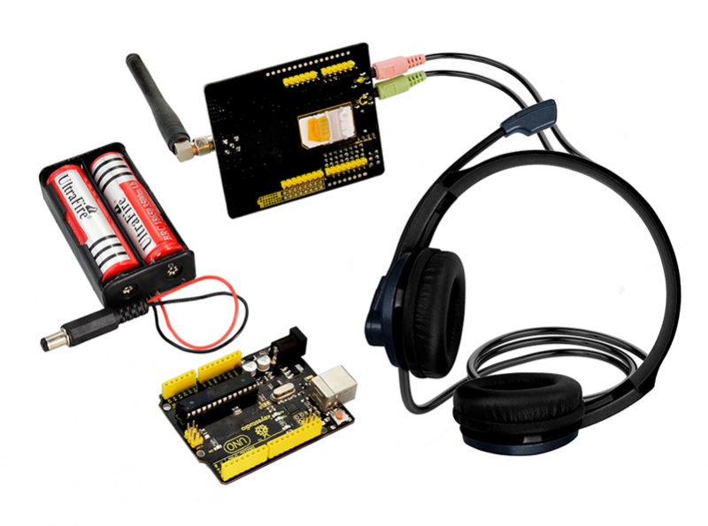
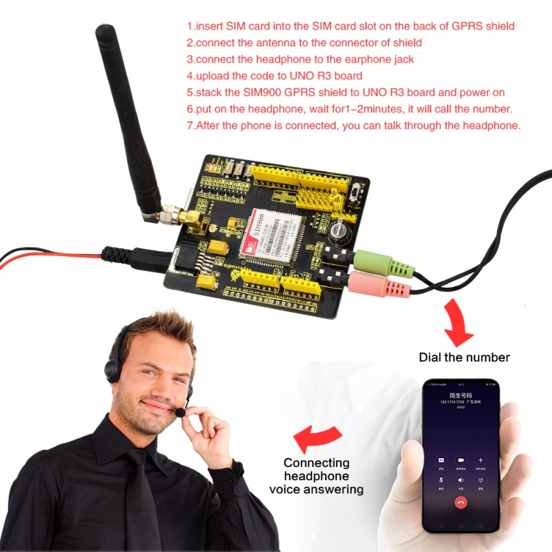
Done uploading the code, connect the earphone and SIM card to the shield, and connect the antenna. Shown below.
Then stack the shield onto UNO R3 board, slide the toggle switch to the UART side, powered on, wait for about 2 minutes, it will dial the number that you have set well in the code. After calling, you can talk through the earphone.
2) For adding serial ports RXD(D0) and TXD(D1): send text
  void sendMeg()
  {
  Serial.println("AT");
  delay(2000);
  Serial.println("AT+CMGF=1");
  delay(2000);
  Serial.println("AT+CMGS=\"15812345678\"");//change into your phone number
  delay(2000);
  Serial.print("ABCDEFGHIJKLMN\r\n");//write the content here
  delay(2000);
  Serial.write(0x1A);
 }
void setup() {
  // put your setup code here, to run once:
  Serial.begin(9600);
}
void loop() {
  // put your main code here, to run repeatedly:
  delay(15*1000);
  sendMeg();
}
Code to Note:
1. Serial.println("AT+CMGS=\"15812345678\"");//change into your phone number
2. Serial.print("ABCDEFGHIJKLMN\r\n");//write the content here
Test Result:
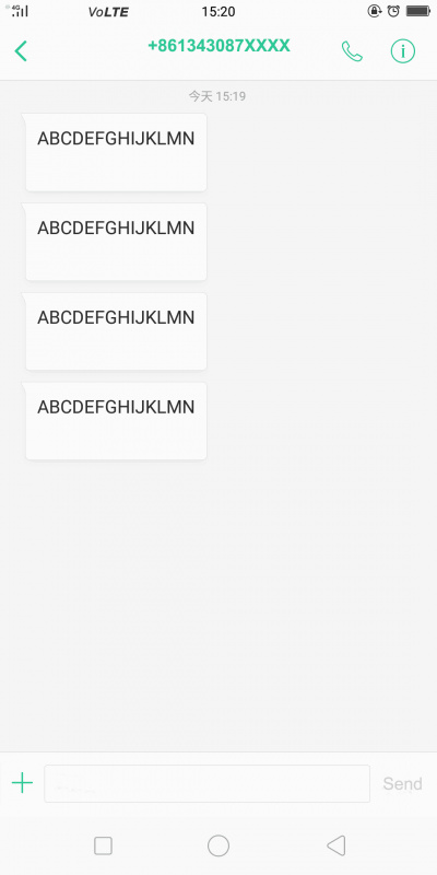
Done uploading the code, insert the SIM card into SIM900 GSM/GPRS shield, and then install the antenna, as well as stack the shield onto UNO R3 board.
Power the UNO R3 board, the PWR LED on the shield lights; long press the SIM900-POWER button, waiting the Stable LED and NET LED light up; release the SIM900-POWER button, wait for a minute, your phone will receive the message sent from SIM900.
3) For adding serial ports RXD(D6) and TXD(D7): call up
#include <SoftwareSerial.h>
SoftwareSerial SIM900(6, 7); // define serial port PIN
void SIM900_Start()
{
  digitalWrite(9, HIGH);
  delay(2000);
  digitalWrite(9, LOW);
  delay(5000);
}
void Call_Phone()
{
  SIM900.println("ATD15812345678;"); // the numbers behind ATD is your phone number to dial.
  delay(100);
  SIM900.println("ATD15812345678;");
  delay(30000);            // wait for 30 seconds...
  SIM900.println("ATH");   // hang up
}
void setup()
{
  pinMode(9, OUTPUT);
  SIM900.begin(19200);   //set baud rate
  SIM900_Start();
  delay(20000);  // wait for SIM900 to work
}
void loop()
{
  Call_Phone();
  do
  {
  }
  while(1);
}
Code to Note:
1.In the code, it will use the library SoftwareSerial.h, you don't need to add it because the software IDE comes with this library.
2.In the code SIM900.println("ATD15812345678;"), you can change the phone number you want to dial.
Shipping List
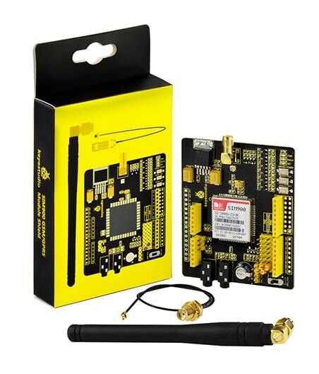
1. keyestudio SIM900 GSM_GPRS Module Shield *1
2. Extension cable 22CM *1
Resources
Download Code:
https://fs.keyestudio.com/KS0142
VIDEO:
http://video.keyestudio.com/ks0142/
