Ks0158 Keyestudio EASY plug starter kit for Arduino: Difference between revisions
Keyestudio (talk | contribs) |
Keyestudio (talk | contribs) |
||
| (22 intermediate revisions by the same user not shown) | |||
| Line 1: | Line 1: | ||
==EASY plug learning kit for Arduino starters== | ==EASY plug learning kit for Arduino starters== | ||
<br>[[File: | <br>[[File:QQ图片20210618172627.png|500px|frameless|thumb]]<br> | ||
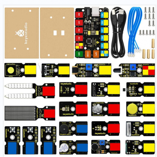
EASY plug starter kit for Arduino<br> | |||
Based on open-source hardware<br> | |||
19 various sensors in one box<br> | |||
For you to make interesting projects<br> | |||
==Summary== | ==Summary== | ||
| Line 13: | Line 13: | ||
What about you and your kids being makers? What about getting creative and making your ideas come true? Well, let's get started right away!<br> | What about you and your kids being makers? What about getting creative and making your ideas come true? Well, let's get started right away!<br> | ||
EASY plug learning kit is developed not only for professional electronic enthusiasts, but also for friends in other lines of work. Even if you have no electronics related knowledge, you can use it to realize your ideas as long as you want to.<br> | EASY plug learning kit is developed not only for professional electronic enthusiasts, but also for friends in other lines of work. Even if you have no electronics related knowledge, you can use it to realize your ideas as long as you want to.<br> | ||
The tutorial of this kit has fully considered the learning interest of beginners. Starting from the basics to more complex lessons, well-arranged content and a connection diagram for every lesson help you get started easily and quickly in learning Arduino.<br> | The tutorial of this kit has fully considered the learning interest of beginners. Starting from the basics to more complex lessons, well-arranged content and a connection diagram for every lesson to help you get started easily and quickly in learning Arduino.<br> | ||
Its unique EASY plug interface makes the wire connection easier than ever! You never have to worry about wrong connection | Its unique EASY plug interface makes the wire connection easier than ever! You never have to worry about wrong connection, complicated soldering or component damage. It's both safe and environmental-friendly. | ||
==Kit List== | ==Kit List== | ||
| Line 165: | Line 165: | ||
|- | |- | ||
|} | |} | ||
==Lesson List== | |||
1.Hello world<br> | |||
2.Who's blinking <br> | |||
3.Visible breath<br> | |||
4.Flowing light<br> | |||
5.Make a sound<br> | |||
6.Who's singing<br> | |||
7.Temperature measuring<br> | |||
8.Make a sound-controlled lamp <br> | |||
9.Make a light-controlled lamp<br> | |||
10.Water level alarm<br> | |||
11.I'm thirsty<br> | |||
12.Visible analog value<br> | |||
13.Magnetic field detecting<br> | |||
14.Collision detecting<br> | |||
15.Button-controlled lamp<br> | |||
16.Touch alarm<br> | |||
17.Knock Sensing<br> | |||
18.Tilt Sensor<br> | |||
19.Fire alarm<br> | |||
20.Vibration alarm<br> | |||
21.Magnetic field detector<br> | |||
22.Temperature alarm<br> | |||
==Lesson Details== | |||
===Lesson 1: Hello world=== | |||
'''Introduction''' | |||
For the first lesson, we will begin with something simple. This lesson is called "Hello World!". This is a communication test of your Arduino and PC, also a primer project for you to have your first try of the Arduino world! | |||
'''Hardware required''' | |||
EASY plug controller Board *1<br> | |||
USB cable *1<br> | |||
'''Sample Code''' | |||
Connect the board to your PC using the USB cable; copy below code into Arduino IDE, and click upload to upload it to your board. | |||
<pre> | |||
int val;// define variable val | |||
void setup() | |||
{ | |||
Serial.begin(9600);// set the baud rate at 9600 to match the software settings. When connected to a specific device, (e.g. Bluetooth), the baud rate needs to be the same with it. | |||
} | |||
void loop() | |||
{ | |||
val=Serial.read();// read the instruction or character from PC to Arduino, and assign them to Val. | |||
if(val=='R')// determine if the instruction or character received is “R” | |||
{ // if it’s “R” | |||
Serial.println("Hello World!");// display “Hello World!” | |||
} | |||
} | |||
</pre> | |||
'''Result''' | |||
Open serial port monitor of the Arduino IDE, input “R”, click “Send”, you can see it displays “Hello World!”. | |||
===Lesson 2: Who's blinking=== | |||
'''Introduction''' | |||
After entry lesson of “Hello World!”, let’s up the stake and learn how to control the blinking of an LED. This lesson is quite simple. All you need to do is to connect an LED to one of the digital pins. We will be using hardware form "Hello World!" and also some extra parts. | |||
'''Hardware required''' | |||
EASY plug controller Board *1<br> | |||
EASY plug cable *1<br> | |||
USB cable *1<br> | |||
EASY plug Digital White LED Module *1<br> | |||
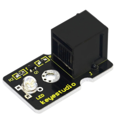
In the hardware list, you can see there is an EASY plug Digital White LED Module. Here is a brief introduction of it. | |||
<br>[[File:15825.png|500px|frameless|thumb]]<br> | |||
This LED module has a bright white color. It’s ideal for Arduino starters. You can easily connect it to the IO port of our EASY plug controller board. Its specifications are as below: | |||
Type: Digital<br> | |||
PH2.54 socket<br> | |||
White LED module<br> | |||
Enables interaction with light-related works<br> | |||
Size: 33.7*20mm<br> | |||
Weight: 5g<br> | |||
'''Connection Diagram''' | |||
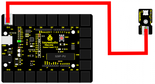
Now, let’s connect this module to the D11 port of the controller board using the EASY plug cable, just as simple as that! | |||
<br>[[File:15826.png|500px|frameless|thumb]]<br> | |||
'''Sample Code''' | |||
Connect the board to your PC using the USB cable; copy below code into Arduino IDE, and click upload to upload it to your board. | |||
<pre> | |||
int ledPin = 11; // define digital pin 11 | |||
void setup() | |||
{ | |||
pinMode(ledPin, OUTPUT);// define LED pin as output | |||
} | |||
void loop() | |||
{ | |||
analogWrite(ledPin,255); //set the LED on, regulate light brightness, ranging from 0-255, 255 is the brightest | |||
delay(1000); // wait for a second | |||
digitalWrite(ledPin, LOW); // set the LED off | |||
delay(1000); // wait for a second | |||
} | |||
</pre> | |||
'''Result''' | |||
The LED will be on for one second, and then off for one second with an interval of one second, just like a shining eye blinking. | |||
===Lesson 3: Visible breath=== | |||
'''Introduction''' | |||
After the first two lessons, I believe you’ve grown familiar with Arduino. In this lesson, we will use the LED to do something else, simulating breath. Sounds cool? Well, let’s get on with it. We will still be using the same hardware form lesson 2. | |||
'''Hardware required''' | |||
EASY plug controller Board *1<br> | |||
EASY plug cable *1<br> | |||
USB cable *1<br> | |||
EASY plug Digital White LED Module *1<br> | |||
'''Connection Diagram''' | |||
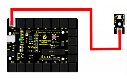
Now, connect the LED module to the D11 port of the controller board using the EASY plug cable. | |||
<br>[[File:15827.png|500px|frameless|thumb]]<br> | |||
'''Sample Code''' | |||
Connect the board to your PC using the USB cable; copy below code into Arduino IDE, and click upload to upload it to your board. | |||
<pre> | |||
int ledPin = 11; // define digital pin 11 | |||
void setup() | |||
{ | |||
pinMode(ledPin, OUTPUT);// define LED pin as output | |||
} | |||
void loop() | |||
{ | |||
for (int a=0; a<=255;a++)// set the LED to be brighter gradually | |||
{ | |||
analogWrite(ledPin,a); // turn on LED, regulate light brightness, ranging from 0-255, 255 is the brightest | |||
delay(10); // wait for 0.01S | |||
} | |||
for (int a=255; a>=0;a--) // set LED to be dimming gradually | |||
{ | |||
analogWrite(ledPin,a); // turn on LED, regulate light brightness, ranging from 0-255, 255 is the brightest | |||
delay(10); // wait for 0.01S | |||
} | |||
delay(1000);// wait for 1S | |||
} | |||
</pre> | |||
'''Result''' | |||
LED becomes brighter gradually, wait for 0.01S, then dimming gradually, wait for 1S, and then cycles on, just like the LED is breathing. | |||
===Lesson 4: Flowing light=== | |||
'''Introduction''' | |||
LED can do many things. I believe you have seen billboards with lights changing to form various patterns. Now, you can make one! This lesson is called Flowing light. We will need 2 more EASY plug cables and 2 more LEDs than the previous lesson. | |||
'''Hardware required''' | |||
EASY plug controller Board *1<br> | |||
EASY plug cable *3<br> | |||
USB cable *1<br> | |||
EASY plug Digital White LED Module *3<br> | |||
'''Connection Diagram''' | |||
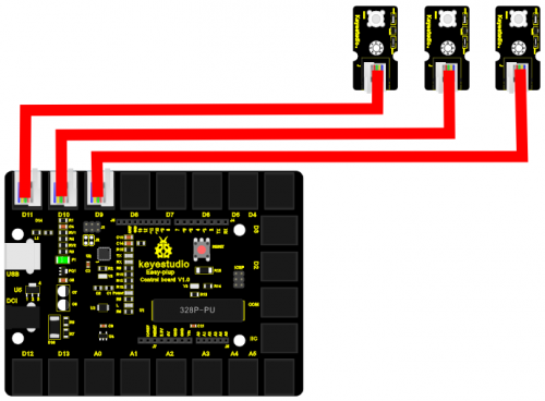
Now, connect the LED modules one by one to D9, D10 and D11 ports of the controller board using the EASY plug cables. | |||
LED becomes brighter gradually, wait for 0.01S, then dimming gradually, wait for 1S, and then cycles on, just like the LED is breathing. | |||
<br>[[File:15828.png|500px|frameless|thumb]]<br> | |||
'''Sample Code''' | |||
Connect the board to your PC using the USB cable; copy below code into Arduino IDE, and click upload to upload it to your board. | |||
<pre> | |||
int BASE = 9 ; // the I/O pin for the first LED | |||
int NUM = 3; // number of LEDs | |||
void setup() | |||
{ | |||
for (int i = BASE; i < BASE + NUM; i ++) | |||
{ | |||
pinMode(i, OUTPUT); // set I/O pins as output | |||
} | |||
} | |||
void loop() | |||
{ | |||
for (int i = BASE; i < BASE + NUM; i ++) | |||
{ | |||
digitalWrite(i, HIGH); //set I/O pins as “high”, turn on LEDs one by one | |||
delay(200); // wait 0.2S | |||
} | |||
for (int i = BASE; i < BASE + NUM; i ++) | |||
{ | |||
digitalWrite(i, HIGH); // set I/O pins as “low”, turn off LEDs one by one | |||
delay(200); // wait 0.2S | |||
} | |||
} | |||
</pre> | |||
'''Result''' | |||
3 LEDs turn on one by one, and then turn off one by one, just like flowing light. | |||
===Lesson 5: Make a sound=== | |||
'''Introduction''' | |||
After many light-related lessons, let’s learn how to make a sound. Sound experiment is usually done with a buzzer or a speaker, while buzzer is simpler and easier to use. In this lesson, we will learn how to make a sound with an active buzzer. | |||
'''Hardware required''' | |||
EASY plug controller Board *1<br> | |||
EASY plug cable *1<br> | |||
USB cable *1<br> | |||
EASY plug Active Buzzer Module *1<br> | |||
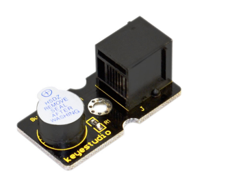
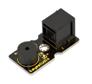
Here is a brief introduction of EASY plug Active Buzzer Module. | |||
<br>[[File:15829.png|500px|frameless|thumb]]<br> | |||
EASY plug Active Buzzer module is the simplest sound making module. It has an inner vibration source. Simply connect it with 5V power supply, it can buzz continuously. With Easy plug design, you can easily plug it into EASY plug controller board to have a try. Below are its specifications: | |||
Working voltage: 3.3-5v<br> | |||
Interface type: digital<br> | |||
Size: 39*20mm<br> | |||
Weight: 6g<br> | |||
'''Connection Diagram''' | |||
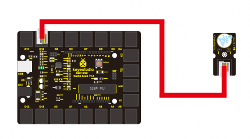
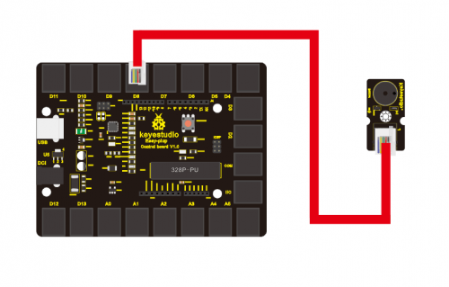
Now, connect the module to the D10 port of the controller board using the EASY plug cable. | |||
<br>[[File:15830.png|500px|frameless|thumb]]<br> | |||
'''Sample Code''' | |||
Connect the board to your PC using the USB cable; copy below code into Arduino IDE, and click upload to upload it to your board. | |||
<pre> | |||
int buzzPin = 10; // Connect Buzzer to D10 | |||
void setup() | |||
{ | |||
pinMode(buzzPin, OUTPUT); // set I/O pin as “output” | |||
} | |||
void loop() | |||
{ | |||
digitalWrite(buzzPin, HIGH);// set digital I/O output as “high”, the buzzer will sound | |||
delay(500);// wait for 0.5S | |||
digitalWrite(buzzPin, LOW);// set digital I/O output as “low”, the buzzer will stop making sound | |||
delay(500); // wait for 0.5S | |||
} | |||
</pre> | |||
'''Result''' | |||
The buzzer will ring for 0.5S and stop making sound for 0.5S. | |||
===Lesson 6: Who's singing=== | |||
'''Introduction''' | |||
In the previous lesson, we have learned how to make a sound. In this lesson, we will use another type of buzzer to code the melody of a song. It’s called a passive buzzer. Using the codes we gave you, this lesson is also quite simple. | |||
'''Hardware required''' | |||
EASY plug controller Board *1<br> | |||
EASY plug cable *1<br> | |||
USB cable *1<br> | |||
EASY plug Passive Buzzer module *1<br> | |||
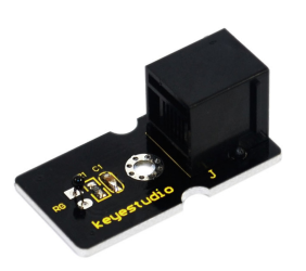
Let’s first learn a little bit about this EASY plug passive Buzzer Module. | |||
<br>[[File:15831.png|500px|frameless|thumb]]<br> | |||
Different from active buzzer, passive buzzer is not set with a vibration source, so DC signal cannot make it buzz. A 2K~5K square wave is used to drive it. Different frequencies produce different sounds. So we can use Arduino to code the melody of a song. Below are its specifications: | |||
Working voltage: 3.3-5v<br> | |||
Interface type: digital<br> | |||
Size: 39*20mm<br> | |||
Weight: 6g<br> | |||
'''Connection Diagram''' | |||
Now, connect the module to the D8 port of the controller board using the EASY plug cable. | |||
<br>[[File:15832.png|500px|frameless|thumb]]<br> | |||
'''Sample Code''' | |||
<pre> | |||
#define D0 -1 | |||
#define D1 262 | |||
#define D2 293 | |||
#define D3 329 | |||
#define D4 349 | |||
#define D5 392 | |||
#define D6 440 | |||
#define D7 494 | |||
#define M1 523 | |||
#define M2 586 | |||
#define M3 658 | |||
#define M4 697 | |||
#define M5 783 | |||
#define M6 879 | |||
#define M7 987 | |||
#define H1 1045 | |||
#define H2 1171 | |||
#define H3 1316 | |||
#define H4 1393 | |||
#define H5 1563 | |||
#define H6 1755 | |||
#define H7 1971 | |||
// List all D tune frequency | |||
#define WHOLE 1 | |||
#define HALF 0.5 | |||
#define QUARTER 0.25 | |||
#define EIGHTH 0.25 | |||
#define SIXTEENTH 0.625 | |||
// list all tempos | |||
int tune[]= // List each frequency according to numbered musical notation | |||
{ | |||
M3,M3,M4,M5, | |||
M5,M4,M3,M2, | |||
M1,M1,M2,M3, | |||
M3,M2,M2, | |||
M3,M3,M4,M5, | |||
M5,M4,M3,M2, | |||
M1,M1,M2,M3, | |||
M2,M1,M1, | |||
M2,M2,M3,M1, | |||
M2,M3,M4,M3,M1, | |||
M2,M3,M4,M3,M2, | |||
M1,M2,D5,D0, | |||
M3,M3,M4,M5, | |||
M5,M4,M3,M4,M2, | |||
M1,M1,M2,M3, | |||
M2,M1,M1 | |||
}; | |||
float durt[]= // list all tempo according to numbered musical notation | |||
{ | |||
1,1,1,1, | |||
1,1,1,1, | |||
1,1,1,1, | |||
1+0.5,0.5,1+1, | |||
1,1,1,1, | |||
1,1,1,1, | |||
1,1,1,1, | |||
1+0.5,0.5,1+1, | |||
1,1,1,1, | |||
1,0.5,0.5,1,1, | |||
1,0.5,0.5,1,1, | |||
1,1,1,1, | |||
1,1,1,1, | |||
1,1,1,0.5,0.5, | |||
1,1,1,1, | |||
1+0.5,0.5,1+1, | |||
}; | |||
int length; | |||
int tonepin=8; // set module signal pin to D8 | |||
void setup() | |||
{ | |||
pinMode(tonepin,OUTPUT); | |||
length=sizeof(tune)/sizeof(tune[0]); // calculate length | |||
} | |||
void loop() | |||
{ | |||
for(int x=0;x<length;x++) | |||
{ | |||
tone(tonepin,tune[x]); | |||
delay(500*durt[x]); // this is use to adjust tempo delay, you can change the number to your liking. | |||
noTone(tonepin); | |||
} | |||
delay(2000); | |||
} | |||
</pre> | |||
'''Result''' | |||
The buzzer will play Ode to Joy, and then pause for 2S. | |||
===Lesson 7: Temperature measuring=== | |||
'''Introduction''' | |||
In this lesson, we will learn how to measure the temperature of our surroundings. You may feel hot or cold sometimes, but how can you know for sure? Well, let’s measure it. | |||
'''Hardware required''' | |||
EASY plug controller Board *1<br> | |||
EASY plug cable *1<br> | |||
USB cable *1<br> | |||
EASY plug Analog Temperature Sensor *1<br> | |||
First, let’s take a look at this EASY plug Analog Temperature Sensor. | |||
<br>[[File:15833.png|500px|frameless|thumb]]<br> | |||
Analog Temperature Sensor is based on the working principle of a thermistor (resistance varies with temperature change in the environment). It can sense temperature change in its surrounding and send the data to the analog I/O in the controller board. Below are its specifications: | |||
Interface type: analog<br> | |||
Working voltage: 5V<br> | |||
Temperature range: -55℃~315℃<br> | |||
Size: 38*20mm<br> | |||
Weight: 5g<br> | |||
'''Connection Diagram''' | |||
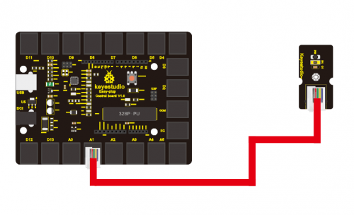
Now, connect the module to the A1 port of the controller board using the EASY plug cable. | |||
<br>[[File:15834.png|500px|frameless|thumb]]<br> | |||
'''Sample Code''' | |||
Connect the board to your PC using the USB cable; copy below code into Arduino IDE, and click upload to upload it to your board. | |||
<pre> | |||
double Thermister(int RawADC) | |||
{ | |||
double Temp; | |||
Temp = log(((10240000/RawADC) - 10000)); | |||
Temp = 1 / (0.001129148 + (0.000234125 + (0.0000000876741 * Temp * Temp ))* Temp ); | |||
Temp = Temp - 273.15; // Convert Kelvin to Celcius | |||
return Temp; | |||
} | |||
void setup() | |||
{ | |||
Serial.begin(9600); | |||
} | |||
void loop() | |||
{ | |||
Serial.print(Thermister(analogRead(1))); // display Fahrenheit | |||
Serial.println(" c"); | |||
delay(500); | |||
} | |||
</pre> | |||
'''Result''' | |||
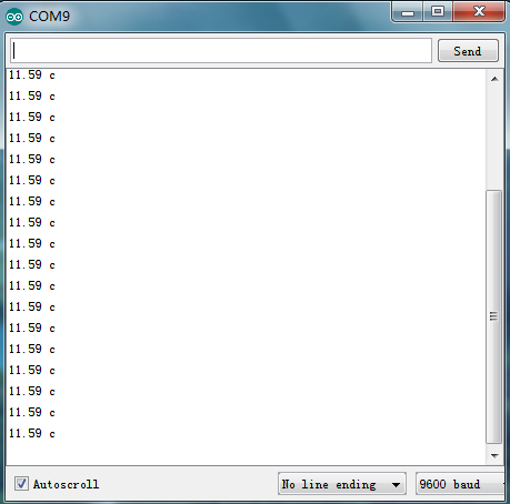
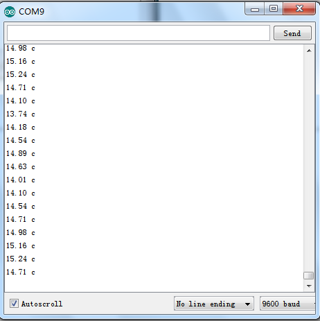
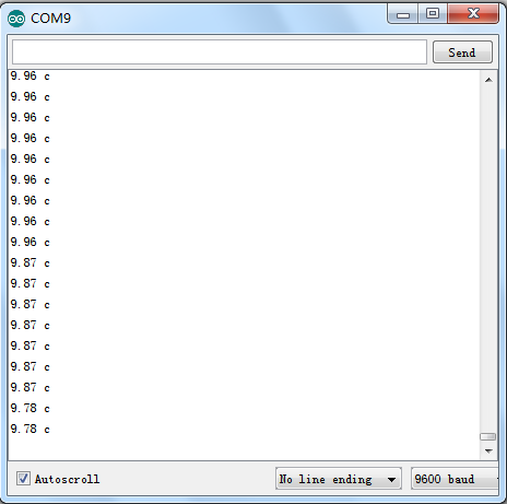
Pic 1 is the temperature the sensor senses in serial monitor; pic 2 is when you blow air with your mouth to the sensor, the temperature goes higher; pic 3 is when you aim a fan to the sensor, the temperature drops. Now, you can know the exact temperature of your surroundings. | |||
Pic 1 | |||
<br>[[File:15835.png|500px|frameless|thumb]]<br> | |||
Pic 2 | |||
<br>[[File:15836.png|500px|frameless|thumb]]<br> | |||
Pic 3 | |||
<br>[[File:15837.png|500px|frameless|thumb]]<br> | |||
===Lesson 8: Make a sound-controlled lamp=== | |||
'''Introduction''' | |||
This is a simple, but interesting lesson. We will make a sound-controlled lamp. Usually, this test is done by clapping your hand. But due to many sound interference in the environment, we will blow air into the sound sensor instead. | |||
'''Hardware required''' | |||
EASY plug controller Board *1<br> | |||
EASY plug cable *1<br> | |||
USB cable *1<br> | |||
EASY plug Digital White LED Module *1<br> | |||
EASY plug Analog Sound Sensor *1<br> | |||
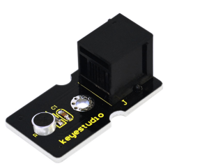
First, let’s learn something about this EASY plug Analog Sound Sensor. | |||
<br>[[File:15838.png|500px|frameless|thumb]]<br> | |||
Analog Sound Sensor is typically used in detecting the loudness in ambient environment. The sound sensor can pick up sound signal and convert it into voltage value. You can use it to make some interesting interactive works such as a voice operated switch or a sound-controlled lamp in this lesson. Below are its specifications: | |||
Supply Voltage: 3.3V to 5V<br> | |||
Detecting sound intensity<br> | |||
Interface: Analog<br> | |||
Size: 38*20mm<br> | |||
Weight: 6g<br> | |||
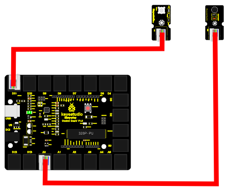
'''Connection Diagram''' | |||
Now, connect the LED module to the D11 port of the controller board, and sound module to A0 using the EASY plug cables. | |||
<br>[[File:15839.png|500px|frameless|thumb]]<br> | |||
'''Sample Code''' | |||
Connect the board to your PC using the USB cable; copy below code into Arduino IDE, and click upload to upload it to your board. | |||
<pre> | |||
int ledpin=11;// set LED to D11 | |||
int soundpin=0;// set sensor to A0 | |||
void setup() | |||
{ | |||
Serial.begin(9600); // open serial port, set the baud rate at 9600 bps | |||
pinMode(ledpin,OUTPUT);// set LED pin as output | |||
} | |||
void loop() | |||
{ | |||
int val; | |||
val=analogRead(soundpin); // read the value of sensor pin and assign it to val | |||
Serial.println(val); | |||
if (val>170) | |||
{ | |||
digitalWrite(ledpin, HIGH); // turn LED ON | |||
} | |||
else | |||
{ | |||
digitalWrite(ledpin, LOW); // turn LED OFF | |||
} | |||
delay(100); | |||
} | |||
</pre> | |||
'''Result''' | |||
When you blow air into the sensor, the air vibrates; the sensor will pick up the sound signal and turn on LED. | |||
===Lesson 9: Make a light-controlled lamp=== | |||
'''Introduction''' | |||
From the lesson title, you know this lesson is very similar to the previous one. In the last one, the LED is controlled by sound; in this one, the LED will be controlled by light. So here, we will use a light-related photocell sensor. | |||
'''Hardware required''' | |||
EASY plug controller Board *1<br> | |||
EASY plug cable *2<br> | |||
USB cable *1<br> | |||
EASY plug Digital White LED Module *1<br> | |||
EASY plug Photocell Sensor *1<br> | |||
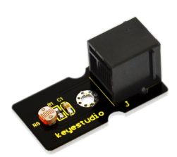
First, a brief introduction of this EASY plug Photocell Sensor. | |||
<br>[[File:15840.png|500px|frameless|thumb]]<br> | |||
Photocell is a semiconductor. It has features of high sensitivity, quick response, spectral characteristic, and R-value consistence, maintaining high stability and reliability in environment extremes such as high temperature, high humidity. It’s widely used in automatic control switch fields. Below are its specifications: | |||
Interface type: analog<br> | |||
Working voltage: 5V<br> | |||
Size: 38*20mm<br> | |||
Weight: 5g<br> | |||
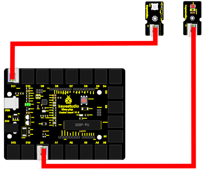
'''Connection Diagram''' | |||
Now, connect the LED module to the D11 port of the controller board, and photocell sensor to A0 port using the EASY plug cables. | |||
<br>[[File:15841.png|500px|frameless|thumb]]<br> | |||
'''Sample Code''' | |||
Connect the board to your PC using the USB cable; copy below code into Arduino IDE, and click upload to upload it to your board. | |||
<pre> | |||
int photopin=0;// set photocell sensor to A0 | |||
int ledpin=11;// set pin11 LED as PWM output to adjust the LED brightness | |||
int val=0;// define variable val | |||
void setup() | |||
{ | |||
pinMode(ledpin,OUTPUT);// set digital pin 11 as output | |||
Serial.begin(9600);// set baud rate to 9600 | |||
} | |||
void loop() | |||
{ | |||
val=analogRead(photopin);// read the analog value of the sensor and assign it to val | |||
Serial.println(val);// display val value | |||
analogWrite(ledpin,val/4);// turn on LED and set to maximum brightness(PWM output is 255) | |||
delay(10);// wait 0.01S | |||
} | |||
</pre> | |||
'''Result''' | |||
When you block light of the sensor, the LED becomes less bright; when you shine light on the sensor, the LED becomes brighter. | |||
===Lesson 10: Water level alarm=== | |||
'''Introduction''' | |||
We are all very familiar with alarms. In this lesson, we will make a water level alarm. This experiment principle can be applied to many occasions. For example, it’s used in washing machines to tell water level. | |||
'''Hardware required''' | |||
EASY plug controller Board *1<br> | |||
EASY plug cable *2<br> | |||
USB cable *1<br> | |||
EASY plug Active Buzzer Module *1<br> | |||
EASY plug Water Sensor *1<br> | |||
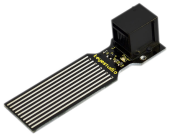
Here is a brief introduction of this EASY plug Water Sensor. | |||
<br>[[File:15842.png|500px|frameless|thumb]]<br> | |||
Our water sensor is easy- to-use, portable and cost-effective, designed to identify and detect water level and water drop. This sensor measures the volume of water drop and water quantity through an array of traces of exposed parallel wires. Compared with its competitors, this sensor is smaller and smarter. Below are its specifications: | |||
Operating voltage: DC5V<br> | |||
Operating current: ﹤20mA<br> | |||
Sensor type: Analog<br> | |||
Detection area: 40mm x16mm<br> | |||
Humanized design: Anti-slippery semi-lunar recess<br> | |||
Operating temperature: 10%~90% without condensation<br> | |||
Size: 68.3 x 20mm<br> | |||
Weight: 5g<br> | |||
'''Connection Diagram''' | |||
Now, connect the LED module to the D11 port of the controller board, and water sensor to A1 port using the EASY plug cables. | |||
<br>[[File:15843.png|500px|frameless|thumb]]<br> | |||
'''Sample Code''' | |||
Connect the board to your PC using the USB cable; copy below code into Arduino IDE, and click upload to upload it to your board. | |||
<pre> | |||
int analogPin = 1; // connect water sensor to analog interface 1 | |||
int buzzPin= 11; // buzzer to digital interface 11 | |||
int val = 0; // define the initial value of variable ‘val’ as 0 | |||
int data = 0; // define the initial value of variable ‘data’ as 0 | |||
void setup() | |||
{ | |||
pinMode(buzzPin, OUTPUT); // define buzzer as output pin | |||
Serial.begin(9600); // set baud rate at 9600 | |||
} | |||
void loop() | |||
{ | |||
val = analogRead(analogPin); // read and assign analog value to variable ’val’ | |||
if(val>400) | |||
{ // decide whether variable ‘val’ is over 400 | |||
digitalWrite(buzzPin,HIGH); // turn on buzzer when variable ‘val’ is over 400 | |||
} | |||
else{ | |||
digitalWrite(buzzPin,LOW); // turn off buzzer when variable ‘val’ is under 400 | |||
} | |||
data = val; // variable ’val’ assigns value to variable ‘data’ | |||
Serial.println(data); // print variable ‘data’ by Serial.print | |||
delay(100); | |||
} | |||
</pre> | |||
'''Result''' | |||
Place the sensor sensing part into water, open serial monitor, you can see the value it displays. When the value is over 400, the buzzer will ring. | |||
===Lesson 11: I'm thirsty=== | |||
'''Introduction''' | |||
Do you have plants? I believe you do. Do you water them often? How do you know when they need water? Well, this alarm here can help you do that. | |||
'''Hardware required''' | |||
EASY plug controller Board *1<br> | |||
EASY plug cable *2<br> | |||
USB cable *1<br> | |||
EASY plug Active Buzzer Module *1<br> | |||
EASY plug Soil humidity Sensor *1<br> | |||
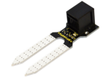
Let’s first take a look at this sensor. | |||
<br>[[File:15844.png|500px|frameless|thumb]]<br> | |||
This soil humidity sensor aims to detect the soil humidity. If the soil is in lack of water, the analog value output by the sensor will decrease, otherwise, it will increase. Together with Arduino, you can make an alarm or an automatic watering device, making your plant more comfortable and your garden smarter. Below are its specifications: | |||
Power Supply Voltage: 3.3V or 5V<br> | |||
Working Current: ≤ 20mA<br> | |||
Output Voltage: 0-2.3V (When the sensor is totally immersed in water, the voltage will be 2.3V), the higher humidity, the higher the output voltage<br> | |||
Sensor type: Analog output<br> | |||
Size: 65.5*20mm<br> | |||
Weight: 5g<br> | |||
'''Connection Diagram''' | |||
Now, connect the buzzer module to the D11 port of the controller board, and soil humidity sensor to A1 port using the EASY plug cables. | |||
<br>[[File:15845.png|500px|frameless|thumb]]<br> | |||
'''Sample Code''' | |||
Connect the board to your PC using the USB cable; copy below code into Arduino IDE, and click upload to upload it to your board. | |||
<pre> | |||
int analogPin = 1; // connect soil humidity sensor to analog interface 1 | |||
int buzzer= 11; // buzzer to digital interface 11 | |||
int val ; | |||
void setup() | |||
{ | |||
pinMode(buzzer, OUTPUT); // define buzzer as output pin | |||
Serial.begin(9600); // set baud rate at 9600 | |||
} | |||
void loop() | |||
{ | |||
val = analogRead(analogPin); // read and assign analog value to variable ’val’ | |||
Serial.print(val); // print variable ‘val’ by Serial.print | |||
if(val<=300) | |||
{ | |||
{ | |||
digitalWrite(buzzer,HIGH); | |||
} | |||
Serial.println(" dry soil"); | |||
delay(50); | |||
} | |||
if((val>300)&&(val<500)) | |||
{ | |||
{ | |||
digitalWrite(buzzer,LOW); | |||
} | |||
Serial.println(" humid soil"); | |||
delay(50); | |||
} | |||
if(val>=500) | |||
{ | |||
{ | |||
digitalWrite(buzzer,HIGH); | |||
} | |||
Serial.println(" in water"); | |||
delay(50); | |||
} | |||
delay(100); | |||
} | |||
</pre> | |||
'''Result''' | |||
Open serial monitor, you can see the value indicating soil humidity; when the value is ≤300, the serial monitor will display “dry soil” and buzzer will ring; when the value is between 300-500, the serial monitor will display “humid soil”; when the value is ≥500, the serial monitor will display “in water” and the buzzer will ring. | |||
===Lesson 12: Visible analog value=== | |||
'''Introduction''' | |||
In this lesson, we will make the mysterious analog value become less mysterious. We will be using the analog rotation sensor, a typical output component of analog value. Together with an LED, we can see clearly if the analog value is changing. | |||
'''Hardware required''' | |||
EASY plug controller Board *1<br> | |||
EASY plug cable *2<br> | |||
USB cable *1<br> | |||
EASY plug Digital White LED Module *1<br> | |||
EASY plug Analog Rotation Sensor *1<br> | |||
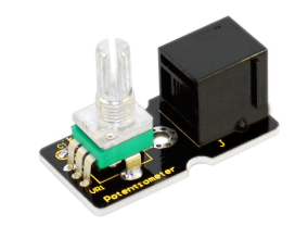
Now, let’s meet this new EASY plug Analog Rotation Sensor. | |||
<br>[[File:15846.png|500px|frameless|thumb]]<br> | |||
This analog Rotation Sensor is Arduino compatible. It is based on a potentiometer. Its voltage can be subdivided into 1024. By rotating it to a certain position, it can output certain voltage value. Below are its specifications: | |||
Supply Voltage: 3.3V to 5V<br> | |||
Interface: Analog<br> | |||
Size: 39*20mm<br> | |||
Weight: 10g<br> | |||
'''Connection Diagram''' | |||
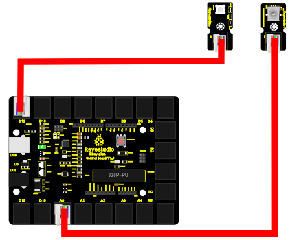
Now, connect the LED module to the D11 port of the controller board, and analog rotation sensor to A0 port using the EASY plug cables. | |||
<br>[[File:15847.png|500px|frameless|thumb]]<br> | |||
'''Sample Code''' | |||
Connect the board to your PC using the USB cable; copy below code into Arduino IDE, and click upload to upload it to your board. | |||
<pre> | |||
int rotatepin=0;// set rotation sensor to A0 | |||
int ledpin=11;// set pin11 LED as PWM output to adjust the LED brightness | |||
int val=0;// define variable val | |||
void setup() | |||
{ | |||
pinMode(ledpin,OUTPUT);// set digital pin 11 as output | |||
Serial.begin(9600);// set baud rate to 9600 | |||
} | |||
void loop() | |||
{ | |||
val=analogRead(rotatepin);// read the analog value of the sensor and assign it to val | |||
Serial.println(val);// display val value | |||
analogWrite(ledpin,val/4);// turn on LED and set to maximum brightness(PWM output is 255) | |||
delay(10);// wait 0.01S | |||
} | |||
</pre> | |||
'''Result''' | |||
By rotating the knob on the module, you can adjust the LED brightness. Now you can see the change of analog value clearly. | |||
===Lesson 13: Magnetic field detecting=== | |||
'''Introduction''' | |||
We know that earth is surrounded by magnetic field. We may not feel it, but it’s critical to our survival. In this lesson, we will teach you how to detect magnetic field of magnetic materials, not the magnetic field of earth because it’s too weak to be detected by this sensor. | |||
'''Hardware required''' | |||
EASY plug controller Board *1<br> | |||
EASY plug cable *2<br> | |||
USB cable x1<br> | |||
Magnetic-iron *1 (not included)<br> | |||
EASY plug Digital White LED Module *1<br> | |||
EASY plug Hall Magnetic Sensor *1<br> | |||
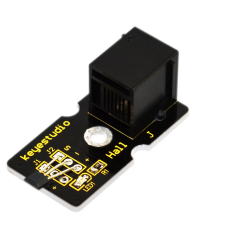
Well, let’s take a look at this EASY plug Hall Magnetic Sensor first. | |||
<br>[[File:15848.png|500px|frameless|thumb]]<br> | |||
This sensor senses the magnetic materials within a detection range up to 75px. The detection range and the strength of the magnetic field are proportional. The output is digital on/off. Below are its specifications: | |||
Detection range: up to 75px<br> | |||
Output: digital on/off<br> | |||
Size: 42.3*20mm<br> | |||
Weight: 5g<br> | |||
'''Connection Diagram''' | |||
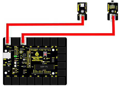
Now, connect the LED module to the D11 port of the controller board, and hall magnetic sensor to D9 port using the EASY plug cables. | |||
<br>[[File:15849.png|500px|frameless|thumb]]<br> | |||
'''Sample Code''' | |||
Connect the board to your PC using the USB cable; copy below code into Arduino IDE, and click upload to upload it to your board. | |||
<pre> | |||
int ledPin = 11; // set LED pin to D11 | |||
int inputPin = 9; // set sensor to input pin 9 | |||
int val = 0; // define variable val | |||
void setup() { | |||
pinMode(ledPin, OUTPUT); // declare LED as output | |||
pinMode(inputPin, INPUT); // declare magnetic sensor as input | |||
} | |||
void loop(){ | |||
val = digitalRead(inputPin); // read input value | |||
if (val == HIGH) { // check if the input is HIGH | |||
digitalWrite(ledPin, LOW); // turn LED OFF | |||
} else { | |||
digitalWrite(ledPin, HIGH); // turn LED ON | |||
} | |||
} | |||
</pre> | |||
'''Result''' | |||
Place the magnetic-iron near the sensor, LED turns on; remove the magnetic-iron, LED turns off. | |||
===Lesson 14: Collision detecting=== | |||
'''Introduction''' | |||
In this lesson, we will use a collision sensor and an LED to detect collision. This lesson is also simple, but you can apply what you learn here to many applications. For example, you can install it to a robot to realize collision detection function. | |||
'''Hardware required''' | |||
EASY plug controller Board *1<br> | |||
EASY plug cable *2<br> | |||
USB cable *1<br> | |||
EASY plug Digital White LED Module *1<br> | |||
EASY plug Collision Sensor *1<br> | |||
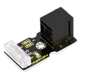
Here is a brief introduction of EASY plug Collision Sensor. | |||
<br>[[File:15850.png|500px|frameless|thumb]]<br> | |||
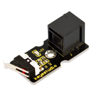
Collision sensor is also known as electronic switch. By programming, it can realize control over light, sound device, key choice function of LCD display etc. Below are its specifications: | |||
Reserving a M3 mounting hole, convenient for fixation on a robot.<br> | |||
With indicator light<br> | |||
Size: 39 * 20mm<br> | |||
Weight: 7g<br> | |||
'''Connection Diagram''' | |||
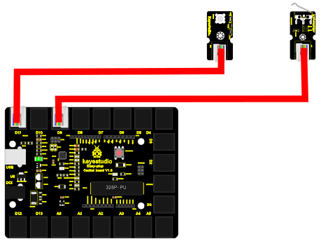
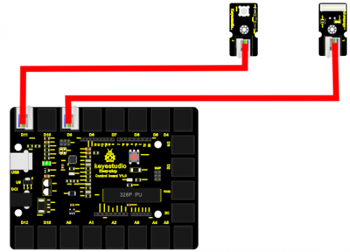
Now, connect the LED module to the D11 port of the controller board, and collision sensor to D9 port using the EASY plug cables. | |||
<br>[[File:15851.png|500px|frameless|thumb]]<br> | |||
'''Sample Code''' | |||
Connect the board to your PC using the USB cable; copy below code into Arduino IDE, and click upload to upload it to your board. | |||
<pre> | |||
int ledpin=11;// set LED to D11 | |||
int inpin=9;// set sensor to D9 | |||
int val;// define variable val | |||
void setup() | |||
{ | |||
pinMode(ledpin,OUTPUT);// set pin LED as output | |||
pinMode(inpin,INPUT);// set collision sensor as input | |||
} | |||
void loop() | |||
{ | |||
val=digitalRead(inpin);// read value on pin 9 and assign it to val | |||
if(val==HIGH)// check if the switch on the module if in closed state; if Yes, turn on LED | |||
{ digitalWrite(ledpin,LOW);} | |||
else | |||
{ digitalWrite(ledpin,HIGH);} | |||
} | |||
</pre> | |||
'''Result''' | |||
You can see on the module, there is a clip, when collision happens, the clip is in closed state, just like a switch, and the LED turns on. Otherwise, LED remains off. | |||
===Lesson 15: Button-controlled lamp=== | |||
'''Introduction''' | |||
In previous lessons, we have learned how to control the LED with various modules. In this lesson, we will use something that is most straightforward, a button. I believe you are all familiar with buttons. When it's pressed, the circuit is in closed (conducting) state. When you release it, the circuit is disconnected. | |||
'''Hardware required''' | |||
EASY plug controller Board *1<br> | |||
EASY plug cable *2<br> | |||
USB cable *1<br> | |||
EASY plug Digital White LED Module *1<br> | |||
EASY plug Digital Push Button *1<br> | |||
First, let’s take a look at this EASY plug Digital Push Button. | |||
<br>[[File:15852.png|500px|frameless|thumb]]<br> | |||
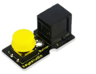
It is a basic application module. You can simply plug it into EASY plug controller board to give it a try. Bellow are its specifications: | |||
Supply Voltage: 3.3V to 5V<br> | |||
Easy to 'plug and play'<br> | |||
Large button and high-quality first-class cap<br> | |||
Interface: Digital<br> | |||
Size: 38*20mm<br> | |||
Weight: 4g<br> | |||
'''Connection Diagram''' | |||
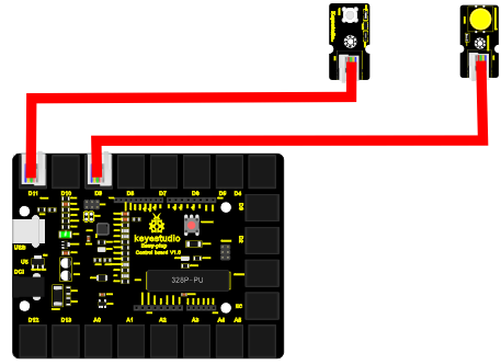
Now, connect the LED module to the D11 port of the controller board, and digital push button to D9 port using the EASY plug cables. | |||
<br>[[File:15853.png|500px|frameless|thumb]]<br> | |||
'''Sample Code''' | |||
Connect the board to your PC using the USB cable; copy below code into Arduino IDE, and click upload to upload it to your board. | |||
<pre> | |||
int ledpin=11;// set LED to pin D11 | |||
int inpin=9;// set button to pin D9 | |||
int val;// define variable val | |||
void setup() | |||
{ | |||
pinMode(ledpin,OUTPUT);// set LED pin as “output” | |||
pinMode(inpin,INPUT);// set button pin as “input” | |||
} | |||
void loop() | |||
{ | |||
val=digitalRead(inpin);// read the level value of pin 9 and assign it to val | |||
if(val==HIGH)// check if the button is pressed, if yes, turn on the LED | |||
{ digitalWrite(ledpin,LOW);} | |||
else | |||
{ digitalWrite(ledpin,HIGH);} | |||
} | |||
</pre> | |||
'''Result''' | |||
When the button is pressed, LED is on, otherwise, LED remains off. | |||
===Lesson 16: Touch alarm=== | |||
'''Introduction''' | |||
In the electronic world, many elements can be used as switches. Here is another one, touch sensor. In this lesson, we will make a touch alarm with this sensor and an active buzzer. When you touch the sensor sensing area, the alarm will go off. | |||
'''Hardware required''' | |||
EASY plug controller Board *1<br> | |||
EASY plug cable *2<br> | |||
USB cable *1<br> | |||
EASY plug Active Buzzer module *1<br> | |||
EASY plug Capacitive Touch Sensor *1<br> | |||
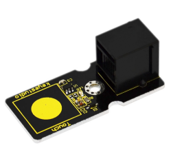
First, let’s first take a look at this EASY plug Capacitive Touch Sensor. | |||
<br>[[File:15854.png|500px|frameless|thumb]]<br> | |||
Are you tired of clicking mechanic button? Well, this little sensor can "feel" people and metal touch and feedback a high/low voltage level. Even isolated by some cloth and paper, it can still feel the touch. Its sensitivity decrease as isolation layer gets thicker. Below are its specifications: | |||
Supply Voltage: 3.3V to 5V<br> | |||
Interface: Digital<br> | |||
Size: 45*20mm<br> | |||
Weight: 5g<br> | |||
'''Connection Diagram''' | |||
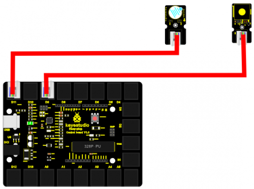
Now, connect the buzzer module to the D11 port of the controller board, and capacitive touch sensor to D9 port using the EASY plug cables. | |||
<br>[[File:15855.png|500px|frameless|thumb]]<br> | |||
'''Sample Code''' | |||
Connect the board to your PC using the USB cable; copy below code into Arduino IDE, and click upload to upload it to your board. | |||
<pre> | |||
int buzzPin = 11; //Connect Buzzer to Digital Pin11 | |||
int inputPin = 9; // Connect Touch sensor to Digital Pin 9 | |||
void setup() { | |||
pinMode(buzzPin, OUTPUT); // declare buzzer as output | |||
pinMode(inputPin, INPUT); // declare Touch sensor as input | |||
} | |||
void loop(){ | |||
int val = digitalRead(inputPin); // read input value | |||
if (val == HIGH) { // check if the input is HIGH | |||
digitalWrite(buzzPin, HIGH); // turn buzzer ON | |||
} else { | |||
digitalWrite(buzzPin, LOW); // turn buzzer OFF | |||
} | |||
} | |||
</pre> | |||
'''Result''' | |||
Use your finger to touch the sensor sensing area, the buzzer will ring; otherwise the buzzer remains silent. | |||
===Lesson 17: Knock Sensing=== | |||
'''Introduction''' | |||
We know sensor can sense all kinds of changes. In this lesson, we will learn how to sense a knock. This sensor has many applications; it can also functions like a switch. | |||
'''Hardware required''' | |||
EASY plug controller Board *1 | |||
EASY plug cable *2 | |||
USB cable *1 | |||
EASY plug Digital White LED Module *1 | |||
EASY plug Knock Sensor *1 | |||
Let’s first take a look at this EASY plug Knock Sensor. | |||
<br>[[File:15856.png|500px|frameless|thumb]]<br> | |||
This module is a knock sensor. When you knock it, it can send a momentary signal. We can combine it with Arduino to make some interesting experiment, e.g. electronic drum. Below are its specifications: | |||
Working voltage: 5V<br> | |||
Size: 38*20mm<br> | |||
Weight: 5g<br> | |||
'''Connection Diagram''' | |||
Now, connect the LED module to the D11 port of the controller board, and knock sensor to D9 port using the EASY plug cables. | |||
<br>[[File:15857.png|500px|frameless|thumb]]<br> | |||
'''Sample Code''' | |||
Connect the board to your PC using the USB cable; copy below code into Arduino IDE, and click upload to upload it to your board. | |||
<pre> | |||
int Led=11;//define LED interface | |||
int knock=9;//define knock sensor interface; | |||
int val;//define digital variable val | |||
void setup() | |||
{ | |||
pinMode(Led,OUTPUT);//define LED pin to be output | |||
pinMode(knock,INPUT);//define knock sensor pin to be input | |||
} | |||
void loop() | |||
{ | |||
val=digitalRead(knock);// read the value of interface9 and assign it to val | |||
if(val==HIGH)// when the knock sensor detect a signal, LED will turn on | |||
{ | |||
digitalWrite(Led,LOW); | |||
} | |||
else | |||
{ | |||
digitalWrite(Led,HIGH); | |||
} | |||
} | |||
</pre> | |||
'''Result''' | |||
Every time you knock the sensor, the LED turns on. Otherwise, it remains off. | |||
===Lesson 18: EASY plug Digital Tilt Sensor=== | |||
'''Introduction''' | |||
In this lesson, we will introduce you another type of switch. It’s called digital tilt sensor. In the test, we will use the sensor to control the on and off of an LED. | |||
'''Hardware required''' | |||
EASY plug controller Board *1<br> | |||
EASY plug cable *2<br> | |||
USB cable *1<br> | |||
EASY plug Digital White LED Module *1<br> | |||
EASY plug Digital Tilt Sensor *1<br> | |||
Here is a brief introduction of EASY plug Digital Tilt Sensor. | |||
<br>[[File:15858.png|500px|frameless|thumb]]<br> | |||
Tilt Sensor is a digital tilt switch. It can be used as a simple tilt sensor. Its principle is simple. Inside the sensor, there is a metal ball. When it’s in upright position, the ball contacts both ends of power supply so circuit is connected; when it’s in upside-down position, circuit is disconnected. Below are its specifications: | |||
Supply Voltage: 3.3V to 5V<br> | |||
Interface: Digital<br> | |||
Size: 39*20mm<br> | |||
Weight: 5g<br> | |||
'''Connection Diagram''' | |||
Now, connect the LED module to the D11 port of the controller board, and digital tilt sensor to D9 port using the EASY plug cables. | |||
<br>[[File:15859.png|500px|frameless|thumb]]<br> | |||
'''Sample Code''' | |||
Connect the board to your PC using the USB cable; copy below code into Arduino IDE, and click upload to upload it to your board. | |||
<pre> | |||
int ledPin = 11; // Connect LED to pin 11 | |||
int tilt = 9; // Connect Tilt sensor to Pin9 | |||
void setup() | |||
{ | |||
pinMode(ledPin, OUTPUT); // Set digital pin 11 as output | |||
pinMode(tilt, INPUT); // Set digital pin 9 as input | |||
} | |||
void loop() | |||
{ | |||
if(digitalRead(tilt)==HIGH) //Read sensor value | |||
{ | |||
digitalWrite(ledPin, HIGH); // Turn on LED when the sensor is triggered | |||
} | |||
else | |||
{ | |||
digitalWrite(ledPin, LOW); // Turn off LED when the sensor is not triggered | |||
} | |||
} | |||
</pre> | |||
'''Result''' | |||
Tilt the sensor to one end, you can see the LED turns on; tilt the sensor to another end, you can see the LED turns off. | |||
===Lesson 19: Fire alarm=== | |||
'''Introduction''' | |||
In this lesson, we will make a commonly seen alarm, fire alarm. Fire alarm is very useful and critical in our life. It has helped save many lives. Similarly to many alarms we’ve made, it includes a sensor and a buzzer. Be careful with the flame when you are doing the test! | |||
'''Hardware required''' | |||
EASY plug controller Board *1<br> | |||
EASY plug cable *2<br> | |||
USB cable *1<br> | |||
Lighter *1 (not included)<br> | |||
EASY plug Active Buzzer module *1<br> | |||
EASY plug Flame Sensor *1<br> | |||
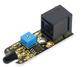
Let’s take a look at this EASY plug flame sensor first. | |||
<br>[[File:15860.png|500px|frameless|thumb]]<br> | |||
This flame sensor can be used to detect fire or other lights whose wavelength stands at 760 nm ~ 1100 nm. In the fire-fighting robot game, the flame plays an important role in the probe, which can be used as the robot's eyes to find fire source. Below are its specifications: | |||
Supply Voltage: 3.3V to 5V<br> | |||
Detection range: 500px (4.8V) ~ 2500px (1V)<br> | |||
Rang of Spectral Bandwidth: 760nm to 1100nm<br> | |||
Operating temperature: -25℃to 85℃<br> | |||
Interface: digital<br> | |||
Size: 49*16.7mm<br> | |||
Weight: 6g<br> | |||
'''Connection Diagram''' | |||
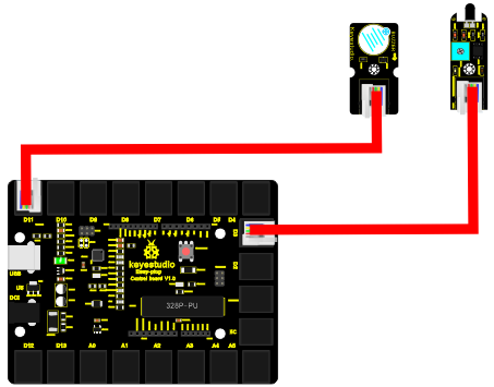
Now, connect the buzzer module to the D11 port of the controller board, and flame sensor to D3 port using the EASY plug cables. | |||
<br>[[File:15861.png|500px|frameless|thumb]]<br> | |||
'''Sample Code''' | |||
Connect the board to your PC using the USB cable; copy below code into Arduino IDE, and click upload to upload it to your board. | |||
<pre> | |||
const int flamePin = 3; // the number of the flame pin | |||
const int buzzPin = 11; // the number of the buzzer pin | |||
// variables will change: | |||
int State = 0; // variable for reading status | |||
void setup() { | |||
// initialize the buzzer pin as an output: | |||
pinMode(buzzPin, OUTPUT); | |||
// initialize the flame pin as an input: | |||
pinMode(flamePin, INPUT); | |||
} | |||
void loop(){ | |||
// read the state of the value: | |||
State = digitalRead(flamePin); | |||
if (State == HIGH) { | |||
// turn buzzer on: | |||
digitalWrite(buzzPin, HIGH); | |||
} | |||
else { | |||
// turn buzzer off: | |||
digitalWrite(buzzPin, LOW); | |||
} | |||
} | |||
</pre> | |||
'''Result''' | |||
Turn on the lighter, put the flame near the flame sensor, the buzzer will ring. | |||
===Lesson 20: Vibration alarm=== | |||
'''Introduction''' | |||
In this lesson, we will make another alarm, which is called a vibration alarm. Do you have something you consider a treasure and wouldn’t want it stolen in any way. Well, this alarm can help you do that. | |||
'''Hardware required''' | |||
EASY plug controller Board *1<br> | |||
EASY plug cable *2<br> | |||
USB cable *1<br> | |||
EASY plug Active Buzzer module *1<br> | |||
EASY plug Vibration Sensor *1<br> | |||
First, let’s get to know a little bit about this EASY plug Vibration Sensor. | |||
<br>[[File:15862.png|500px|frameless|thumb]]<br> | |||
This sensor offers the simplest way to check vibration with Arduino. Directly plug it into EASY plug main board, Arduino will receive a digital signal. | |||
Despite its simplicity, you can make full use of it with creative thinking, step counting, and crash warning light, vibration alarm in this lesson etc. Below are its specifications: | |||
IO Type: Digital<br> | |||
Supply Voltage: 3.3V to 5V<br> | |||
Size: 46.4*16.6mm<br> | |||
Weight: 7g<br> | |||
'''Connection Diagram''' | |||
Now, connect the buzzer module to the D11 port of the controller board, and vibration sensor to D9 port using the EASY plug cables. | |||
<br>[[File:15863.png|500px|frameless|thumb]]<br> | |||
'''Sample Code''' | |||
Connect the board to your PC using the USB cable; copy below code into Arduino IDE, and click upload to upload it to your board. | |||
<pre> | |||
#define buzzPin 11 | |||
#define SensorINPUT 3 //Connect the sensor to digital Pin 3 which is Interrupt 1. | |||
unsigned char state = 0; | |||
void setup() | |||
{ | |||
pinMode(buzzPin, OUTPUT); | |||
pinMode(SensorINPUT, INPUT); | |||
attachInterrupt(1, blink, FALLING);// Trigger the blink function when the falling edge is detected | |||
} | |||
void loop() | |||
{ if(state!=0) | |||
{ | |||
state = 0; | |||
digitalWrite(buzzPin,HIGH); | |||
delay(500); | |||
} | |||
else | |||
digitalWrite(buzzPin,LOW); | |||
} | |||
void blink()//Interrupts function | |||
{ state++; | |||
} | |||
</pre> | |||
'''Result''' | |||
Place the sensor on the desk, use your hand to gently hit the desk; the sensor will sense the vibration and the buzzer will ring. | |||
===Lesson 21: Magnetic field detector=== | |||
'''Introduction''' | |||
In lesson 13, we have learned how to detect magnetic field. This lesson is similar, is also about detecting the magnetic field, but with different modules and different result. | |||
'''Hardware required''' | |||
EASY plug controller Board *1<br> | |||
EASY plug cable *2<br> | |||
USB cable *1<br> | |||
Magnetic-iron *1 (not included)<br> | |||
EASY plug Active Buzzer module *1<br> | |||
EASY plug Reed Switch Module *1<br> | |||
Here is a brief introduction of EASY plug Reed Switch Module. | |||
<br>[[File:15864.png|500px|frameless|thumb]]<br> | |||
Reed Switch is a special switch and a main component for reed relay and proximity switch. Reed switch is usually comprised of two soft magnetic material and metal reed contacts which will disconnect itself when there is no magnetic. Below are its specifications: | |||
Working voltage: DC 3.3V-5V<br> | |||
Working current: ≥20mA<br> | |||
Working temperature: -10℃—+50℃<br> | |||
Detection distance: ≤10mm<br> | |||
IO Interface: 3 wire interface (-/+/S)<br> | |||
Size: 39*20mm<br> | |||
Weight: 5g<br> | |||
'''Connection Diagram''' | |||
Now, connect the buzzer module to the D11 port of the controller board, and reed switch module to D3 port using the EASY plug cables. | |||
<br>[[File:15865.png|500px|frameless|thumb]]<br> | |||
'''Sample Code''' | |||
Connect the board to your PC using the USB cable; copy below code into Arduino IDE, and click upload to upload it to your board. | |||
<pre> | |||
int buzzPin = 11; // Connect Buzzer on Digital Pin11 | |||
int reedpin= 3; // define reed switch sensor interface | |||
int val;// define digital variable val | |||
void setup() | |||
{ | |||
pinMode(buzzPin,OUTPUT);// define buzzer as output interface | |||
pinMode(buttonpin,INPUT);// define reed switch sensor as output interface | |||
} | |||
void loop() | |||
{ | |||
val=digitalRead(reedpin);// read and assign the value of digital interface 3 to val if(val==HIGH)// When a signal is detected by reed switch sensor,Buzzer will on | |||
{ | |||
digitalWrite(buzzPin,LOW); | |||
} | |||
else | |||
{ | |||
digitalWrite(buzzPin,HIGH); | |||
} | |||
} | |||
</pre> | |||
'''Result''' | |||
Place the magnetic-iron near the reed switch module; when the module senses the magnetic field, the LED on the module will turn on; at the same time, buzzer will ring. | |||
===Lesson 22: Temperature alarm=== | |||
'''Introduction''' | |||
As a final lesson in this kit, this is relatively more complicated for it involves three different modules. But don’t worry. I believe you will also find it simple as you have learned so much in previous lessons. | |||
In this lesson, when the temperature reaches a certain value, here 25℃, the alarm will go off. | |||
'''Hardware required''' | |||
EASY plug controller Board *1<br> | |||
EASY plug cable *3<br> | |||
USB cable *1<br> | |||
EASY plug Active Buzzer module *1<br> | |||
EASY plug Digital White LED module *1<br> | |||
EASY plug LM35 Temperature Sensor *1<br> | |||
First, take a look at thisEASY plug LM35 Temperature Sensor. | |||
<br>[[File:15866.png|500px|frameless|thumb]]<br> | |||
LM35 Linear Temperature Sensor is based on semiconductor LM35 temperature sensor. It can be used to detect ambient air temperature. This sensor offers a functional range among 0 degree Celsius to 100 degree Celsius. Sensitivity is 10mV per degree Celsius. The output voltage is proportional to the temperature. | |||
This sensor is commonly used as a temperature measurement sensor. Below are its specifications: | |||
Can be used to detect ambient air temperature<br> | |||
Sensitivity: 10mV per degree Celcius<br> | |||
Functional range: 0 degree Celsius to 100 degree Celsius<br> | |||
Size: 38*20mm<br> | |||
Weight: 5g<br> | |||
'''Connection Diagram''' | |||
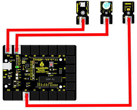
Now, connect the LED module to the D11 port of the controller board, buzzer module to D10, and LM35 temperature sensor to A0 port using the EASY plug cables. | |||
<br>[[File:15867.png|500px|frameless|thumb]]<br> | |||
'''Sample Code''' | |||
Connect the board to your PC using the USB cable; copy below code into Arduino IDE, and click upload to upload it to your board. | |||
<pre> | |||
int buzzPin = 10; | |||
int ledpin= 11; | |||
void setup() | |||
{ | |||
Serial.begin(9600);// Set Baud Rate to 9600 bps | |||
pinMode(ledpin,OUTPUT);// define LED as output | |||
pinMode(buzzPin,OUTPUT);// define buzzer as output | |||
} | |||
void loop() | |||
{ int val; | |||
int dat; | |||
val=analogRead(0);// Connect LM35 on Analog 0 | |||
dat=(500 * val) /1024; | |||
Serial.print("Temp:"); // Display the temperature on Serial monitor | |||
Serial.print(dat); | |||
Serial.println("C"); | |||
if (dat>25) // when temperature is higher than 25℃, LED will be turned on, and buzzer will ring | |||
{ | |||
digitalWrite(buzzPin, HIGH); // turn buzzer ON | |||
digitalWrite(ledpin, HIGH); // turn LED ON | |||
} | |||
else | |||
{ | |||
digitalWrite(buzzPin, LOW); // turn buzzer OFF | |||
digitalWrite(ledpin, LOW); // turn LED OFF | |||
} | |||
delay(500); | |||
} | |||
</pre> | |||
'''Result''' | |||
Open serial monitor, you can see the current temperature. When the temperature goes higher that 25℃ (you can blow air with your month to the module to make the temperature go higher or you can change the 25 here if (dat>25) to a lower value ), the LED will be turned on, and the buzzer will ring. | |||
Resource | |||
https://fs.keyestudio.com/KS0158 | |||
==Buy from == | |||
'''Official Website''' | |||
http://www.keyestudio.com/keyestudio-easy-plug-starter-kit-for-arduino.html | |||
[[Category: Start Kit]] | |||
Latest revision as of 17:32, 18 June 2021
EASY plug learning kit for Arduino starters
EASY plug starter kit for Arduino
Based on open-source hardware
19 various sensors in one box
For you to make interesting projects
Summary
What about you and your kids being makers? What about getting creative and making your ideas come true? Well, let's get started right away!
EASY plug learning kit is developed not only for professional electronic enthusiasts, but also for friends in other lines of work. Even if you have no electronics related knowledge, you can use it to realize your ideas as long as you want to.
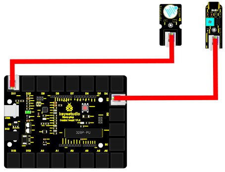
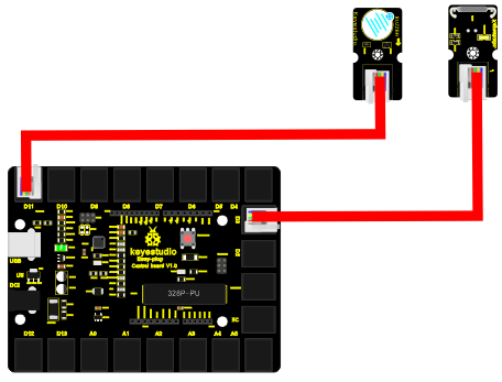
The tutorial of this kit has fully considered the learning interest of beginners. Starting from the basics to more complex lessons, well-arranged content and a connection diagram for every lesson to help you get started easily and quickly in learning Arduino.
Its unique EASY plug interface makes the wire connection easier than ever! You never have to worry about wrong connection, complicated soldering or component damage. It's both safe and environmental-friendly.
Kit List
Lesson List
1.Hello world
2.Who's blinking
3.Visible breath
4.Flowing light
5.Make a sound
6.Who's singing
7.Temperature measuring
8.Make a sound-controlled lamp
9.Make a light-controlled lamp
10.Water level alarm
11.I'm thirsty
12.Visible analog value
13.Magnetic field detecting
14.Collision detecting
15.Button-controlled lamp
16.Touch alarm
17.Knock Sensing
18.Tilt Sensor
19.Fire alarm
20.Vibration alarm
21.Magnetic field detector
22.Temperature alarm
Lesson Details
Lesson 1: Hello world
Introduction
For the first lesson, we will begin with something simple. This lesson is called "Hello World!". This is a communication test of your Arduino and PC, also a primer project for you to have your first try of the Arduino world!
Hardware required
EASY plug controller Board *1
USB cable *1
Sample Code
Connect the board to your PC using the USB cable; copy below code into Arduino IDE, and click upload to upload it to your board.
int val;// define variable val
void setup()
{
  Serial.begin(9600);// set the baud rate at 9600 to match the software settings. When connected to a specific device, (e.g. Bluetooth), the baud rate needs to be the same with it.
}
void loop()
{
  val=Serial.read();// read the instruction or character from PC to Arduino, and assign them to Val.
  if(val=='R')//  determine if the instruction or character received is “R”
  {  // if it’s “R”
   Serial.println("Hello World!");// display “Hello World!”
  }
}
Result
Open serial port monitor of the Arduino IDE, input “R”, click “Send”, you can see it displays “Hello World!”.
Lesson 2: Who's blinking
Introduction
After entry lesson of “Hello World!”, let’s up the stake and learn how to control the blinking of an LED. This lesson is quite simple. All you need to do is to connect an LED to one of the digital pins. We will be using hardware form "Hello World!" and also some extra parts.
Hardware required
EASY plug controller Board *1
EASY plug cable *1
USB cable *1
EASY plug Digital White LED Module *1
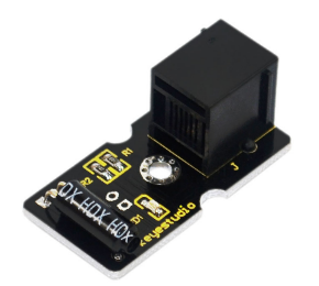
In the hardware list, you can see there is an EASY plug Digital White LED Module. Here is a brief introduction of it.
This LED module has a bright white color. It’s ideal for Arduino starters. You can easily connect it to the IO port of our EASY plug controller board. Its specifications are as below:
Type: Digital
PH2.54 socket
White LED module
Enables interaction with light-related works
Size: 33.7*20mm
Weight: 5g
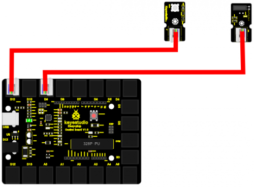
Connection Diagram
Now, let’s connect this module to the D11 port of the controller board using the EASY plug cable, just as simple as that!
Sample Code
Connect the board to your PC using the USB cable; copy below code into Arduino IDE, and click upload to upload it to your board.
int ledPin = 11; // define digital pin 11
void setup()
{
pinMode(ledPin, OUTPUT);// define LED pin as output
}
void loop()
{
analogWrite(ledPin,255); //set the LED on, regulate light brightness, ranging from 0-255, 255 is the brightest
delay(1000); // wait for a second
digitalWrite(ledPin, LOW); // set the LED off
delay(1000); // wait for a second
}
Result
The LED will be on for one second, and then off for one second with an interval of one second, just like a shining eye blinking.
Lesson 3: Visible breath
Introduction
After the first two lessons, I believe you’ve grown familiar with Arduino. In this lesson, we will use the LED to do something else, simulating breath. Sounds cool? Well, let’s get on with it. We will still be using the same hardware form lesson 2.
Hardware required
EASY plug controller Board *1
EASY plug cable *1
USB cable *1
EASY plug Digital White LED Module *1
Connection Diagram
Now, connect the LED module to the D11 port of the controller board using the EASY plug cable.
Sample Code
Connect the board to your PC using the USB cable; copy below code into Arduino IDE, and click upload to upload it to your board.
int ledPin = 11; // define digital pin 11
void setup()
{
pinMode(ledPin, OUTPUT);// define LED pin as output
}
void loop()
{
for (int a=0; a<=255;a++)// set the LED to be brighter gradually
{
analogWrite(ledPin,a); // turn on LED, regulate light brightness, ranging from 0-255, 255 is the brightest
delay(10); // wait for 0.01S
}
for (int a=255; a>=0;a--) // set LED to be dimming gradually
{
analogWrite(ledPin,a); // turn on LED, regulate light brightness, ranging from 0-255, 255 is the brightest
delay(10); // wait for 0.01S
}
delay(1000);// wait for 1S
}
Result
LED becomes brighter gradually, wait for 0.01S, then dimming gradually, wait for 1S, and then cycles on, just like the LED is breathing.
Lesson 4: Flowing light
Introduction
LED can do many things. I believe you have seen billboards with lights changing to form various patterns. Now, you can make one! This lesson is called Flowing light. We will need 2 more EASY plug cables and 2 more LEDs than the previous lesson.
Hardware required
EASY plug controller Board *1
EASY plug cable *3
USB cable *1
EASY plug Digital White LED Module *3
Connection Diagram
Now, connect the LED modules one by one to D9, D10 and D11 ports of the controller board using the EASY plug cables. LED becomes brighter gradually, wait for 0.01S, then dimming gradually, wait for 1S, and then cycles on, just like the LED is breathing.
Sample Code
Connect the board to your PC using the USB cable; copy below code into Arduino IDE, and click upload to upload it to your board.
int BASE = 9 ;  // the I/O pin for the first LED
int NUM = 3;   //  number of LEDs
void setup()
{
   for (int i = BASE; i < BASE + NUM; i ++)
   {
     pinMode(i, OUTPUT);   // set I/O pins as output
   }
}

void loop()
{
   for (int i = BASE; i < BASE + NUM; i ++)
   {
     digitalWrite(i, HIGH);    //set I/O pins as “high”, turn on LEDs one by one
     delay(200);        // wait 0.2S
   }
   for (int i = BASE; i < BASE + NUM; i ++)
   {
     digitalWrite(i, HIGH);    // set I/O pins as “low”, turn off LEDs one by one
     delay(200);        // wait 0.2S
   }
}
Result
3 LEDs turn on one by one, and then turn off one by one, just like flowing light.
Lesson 5: Make a sound
Introduction
After many light-related lessons, let’s learn how to make a sound. Sound experiment is usually done with a buzzer or a speaker, while buzzer is simpler and easier to use. In this lesson, we will learn how to make a sound with an active buzzer.
Hardware required
EASY plug controller Board *1
EASY plug cable *1
USB cable *1
EASY plug Active Buzzer Module *1
Here is a brief introduction of EASY plug Active Buzzer Module.
EASY plug Active Buzzer module is the simplest sound making module. It has an inner vibration source. Simply connect it with 5V power supply, it can buzz continuously. With Easy plug design, you can easily plug it into EASY plug controller board to have a try. Below are its specifications:
Working voltage: 3.3-5v
Interface type: digital
Size: 39*20mm
Weight: 6g
Connection Diagram
Now, connect the module to the D10 port of the controller board using the EASY plug cable.
Sample Code
Connect the board to your PC using the USB cable; copy below code into Arduino IDE, and click upload to upload it to your board.
int buzzPin =  10; // Connect Buzzer to D10
void setup()
{
 pinMode(buzzPin, OUTPUT);  // set I/O pin as “output”
}
void loop()
{
 digitalWrite(buzzPin, HIGH);// set digital I/O output as “high”, the buzzer will sound
 delay(500);// wait for 0.5S
 digitalWrite(buzzPin, LOW);// set digital I/O output as “low”, the buzzer will stop making sound
 delay(500); // wait for 0.5S
}
Result
The buzzer will ring for 0.5S and stop making sound for 0.5S.
Lesson 6: Who's singing
Introduction
In the previous lesson, we have learned how to make a sound. In this lesson, we will use another type of buzzer to code the melody of a song. It’s called a passive buzzer. Using the codes we gave you, this lesson is also quite simple.
Hardware required
EASY plug controller Board *1
EASY plug cable *1
USB cable *1
EASY plug Passive Buzzer module *1
Let’s first learn a little bit about this EASY plug passive Buzzer Module.
Different from active buzzer, passive buzzer is not set with a vibration source, so DC signal cannot make it buzz. A 2K~5K square wave is used to drive it. Different frequencies produce different sounds. So we can use Arduino to code the melody of a song. Below are its specifications:
Working voltage: 3.3-5v
Interface type: digital
Size: 39*20mm
Weight: 6g
Connection Diagram
Now, connect the module to the D8 port of the controller board using the EASY plug cable.
Sample Code
#define D0 -1
#define D1 262
#define D2 293
#define D3 329
#define D4 349
#define D5 392
#define D6 440
#define D7 494

#define M1 523
#define M2 586
#define M3 658
#define M4 697
#define M5 783
#define M6 879
#define M7 987

#define H1 1045
#define H2 1171
#define H3 1316
#define H4 1393
#define H5 1563
#define H6 1755
#define H7 1971
// List all D tune frequency
#define WHOLE 1
#define HALF 0.5
#define QUARTER 0.25
#define EIGHTH 0.25
#define SIXTEENTH 0.625
// list all tempos
int tune[]=        // List each frequency according to numbered musical notation
{
  M3,M3,M4,M5,
  M5,M4,M3,M2,
  M1,M1,M2,M3,
  M3,M2,M2,
  M3,M3,M4,M5,
  M5,M4,M3,M2,
  M1,M1,M2,M3,
  M2,M1,M1,
  M2,M2,M3,M1,
  M2,M3,M4,M3,M1,
  M2,M3,M4,M3,M2,
  M1,M2,D5,D0,
  M3,M3,M4,M5,
  M5,M4,M3,M4,M2,
  M1,M1,M2,M3,
  M2,M1,M1
};
float durt[]=       // list all tempo according to numbered musical notation
{
  1,1,1,1,
  1,1,1,1,
  1,1,1,1,
  1+0.5,0.5,1+1,
  1,1,1,1,
  1,1,1,1,
  1,1,1,1,
  1+0.5,0.5,1+1,
  1,1,1,1,
  1,0.5,0.5,1,1,
  1,0.5,0.5,1,1,
  1,1,1,1,
  1,1,1,1,
  1,1,1,0.5,0.5,
  1,1,1,1,
  1+0.5,0.5,1+1,
};
int length;
int tonepin=8;   // set module signal pin to D8
void setup()
{
  pinMode(tonepin,OUTPUT);
  length=sizeof(tune)/sizeof(tune[0]);   // calculate length

}
void loop()
{
  for(int x=0;x<length;x++)
  {
    tone(tonepin,tune[x]);
    delay(500*durt[x]);   // this is use to adjust tempo delay, you can change the number to your liking.
    noTone(tonepin);
  }
  delay(2000);
}
Result
The buzzer will play Ode to Joy, and then pause for 2S.
Lesson 7: Temperature measuring
Introduction
In this lesson, we will learn how to measure the temperature of our surroundings. You may feel hot or cold sometimes, but how can you know for sure? Well, let’s measure it.
Hardware required
EASY plug controller Board *1
EASY plug cable *1
USB cable *1
EASY plug Analog Temperature Sensor *1
First, let’s take a look at this EASY plug Analog Temperature Sensor.
Analog Temperature Sensor is based on the working principle of a thermistor (resistance varies with temperature change in the environment). It can sense temperature change in its surrounding and send the data to the analog I/O in the controller board. Below are its specifications:
Interface type: analog
Working voltage: 5V
Temperature range: -55℃~315℃
Size: 38*20mm
Weight: 5g
Connection Diagram
Now, connect the module to the A1 port of the controller board using the EASY plug cable.
Sample Code
Connect the board to your PC using the USB cable; copy below code into Arduino IDE, and click upload to upload it to your board.
double Thermister(int RawADC)
{
double Temp;
Temp = log(((10240000/RawADC) - 10000));
Temp = 1 / (0.001129148 + (0.000234125 + (0.0000000876741 * Temp * Temp ))* Temp );
Temp = Temp - 273.15; // Convert Kelvin to Celcius
return Temp;
}
void setup()
{
Serial.begin(9600);
}
void loop()
{
Serial.print(Thermister(analogRead(1))); // display Fahrenheit
Serial.println(" c");
delay(500);
}
Result
Pic 1 is the temperature the sensor senses in serial monitor; pic 2 is when you blow air with your mouth to the sensor, the temperature goes higher; pic 3 is when you aim a fan to the sensor, the temperature drops. Now, you can know the exact temperature of your surroundings.
Pic 1
Pic 2
Pic 3
Lesson 8: Make a sound-controlled lamp
Introduction
This is a simple, but interesting lesson. We will make a sound-controlled lamp. Usually, this test is done by clapping your hand. But due to many sound interference in the environment, we will blow air into the sound sensor instead.
Hardware required
EASY plug controller Board *1
EASY plug cable *1
USB cable *1
EASY plug Digital White LED Module *1
EASY plug Analog Sound Sensor *1
First, let’s learn something about this EASY plug Analog Sound Sensor.
Analog Sound Sensor is typically used in detecting the loudness in ambient environment. The sound sensor can pick up sound signal and convert it into voltage value. You can use it to make some interesting interactive works such as a voice operated switch or a sound-controlled lamp in this lesson. Below are its specifications:
Supply Voltage: 3.3V to 5V
Detecting sound intensity
Interface: Analog
Size: 38*20mm
Weight: 6g
Connection Diagram
Now, connect the LED module to the D11 port of the controller board, and sound module to A0 using the EASY plug cables.
Sample Code
Connect the board to your PC using the USB cable; copy below code into Arduino IDE, and click upload to upload it to your board.
int ledpin=11;// set LED to D11
int soundpin=0;// set sensor to A0
void setup()
{
 Serial.begin(9600); // open serial port, set the baud rate at 9600 bps
 pinMode(ledpin,OUTPUT);// set LED pin as output
}
void loop()
{
 int val;
 val=analogRead(soundpin);   // read the value of sensor pin and assign it to val
 Serial.println(val);
 if (val>170)
  {
  digitalWrite(ledpin, HIGH);  // turn LED ON
  }
 else
  {
   digitalWrite(ledpin, LOW); // turn LED OFF
  }
  delay(100);
}
Result
When you blow air into the sensor, the air vibrates; the sensor will pick up the sound signal and turn on LED.
Lesson 9: Make a light-controlled lamp
Introduction
From the lesson title, you know this lesson is very similar to the previous one. In the last one, the LED is controlled by sound; in this one, the LED will be controlled by light. So here, we will use a light-related photocell sensor.
Hardware required
EASY plug controller Board *1
EASY plug cable *2
USB cable *1
EASY plug Digital White LED Module *1
EASY plug Photocell Sensor *1
First, a brief introduction of this EASY plug Photocell Sensor.
Photocell is a semiconductor. It has features of high sensitivity, quick response, spectral characteristic, and R-value consistence, maintaining high stability and reliability in environment extremes such as high temperature, high humidity. It’s widely used in automatic control switch fields. Below are its specifications:
Interface type: analog
Working voltage: 5V
Size: 38*20mm
Weight: 5g
Connection Diagram
Now, connect the LED module to the D11 port of the controller board, and photocell sensor to A0 port using the EASY plug cables.
Sample Code
Connect the board to your PC using the USB cable; copy below code into Arduino IDE, and click upload to upload it to your board.
int photopin=0;// set photocell sensor to A0
int ledpin=11;// set pin11 LED as PWM output to adjust the LED brightness
int val=0;// define variable val
void setup()
{
pinMode(ledpin,OUTPUT);// set digital pin 11 as output
Serial.begin(9600);// set baud rate to 9600
}
void loop()
{
val=analogRead(photopin);// read the analog value of the sensor and assign it to val
Serial.println(val);// display val value
analogWrite(ledpin,val/4);// turn on LED and set to maximum brightness(PWM output is 255)
delay(10);// wait 0.01S
}
Result
When you block light of the sensor, the LED becomes less bright; when you shine light on the sensor, the LED becomes brighter.
Lesson 10: Water level alarm
Introduction
We are all very familiar with alarms. In this lesson, we will make a water level alarm. This experiment principle can be applied to many occasions. For example, it’s used in washing machines to tell water level.
Hardware required
EASY plug controller Board *1
EASY plug cable *2
USB cable *1
EASY plug Active Buzzer Module *1
EASY plug Water Sensor *1
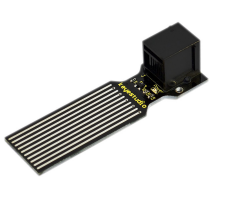
Here is a brief introduction of this EASY plug Water Sensor.
Our water sensor is easy- to-use, portable and cost-effective, designed to identify and detect water level and water drop. This sensor measures the volume of water drop and water quantity through an array of traces of exposed parallel wires. Compared with its competitors, this sensor is smaller and smarter. Below are its specifications:
Operating voltage: DC5V
Operating current: ﹤20mA
Sensor type: Analog
Detection area: 40mm x16mm
Humanized design: Anti-slippery semi-lunar recess
Operating temperature: 10%~90% without condensation
Size: 68.3 x 20mm
Weight: 5g
Connection Diagram
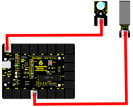
Now, connect the LED module to the D11 port of the controller board, and water sensor to A1 port using the EASY plug cables.
Sample Code
Connect the board to your PC using the USB cable; copy below code into Arduino IDE, and click upload to upload it to your board.
int analogPin = 1; // connect water sensor to analog interface 1
int buzzPin= 11; // buzzer to digital interface 11
int val = 0; // define the initial value of variable ‘val’ as 0
int data = 0; // define the initial value of variable ‘data’ as 0
void setup()
{
pinMode(buzzPin, OUTPUT); // define buzzer as output pin
Serial.begin(9600); // set baud rate at 9600
}
void loop()
{
val = analogRead(analogPin); // read and assign analog value to variable ’val’
if(val>400)
{ // decide whether variable ‘val’ is over 400
digitalWrite(buzzPin,HIGH); // turn on buzzer when variable ‘val’ is over 400
}
else{
digitalWrite(buzzPin,LOW); // turn off buzzer when variable ‘val’ is under 400
}
data = val; // variable ’val’ assigns value to variable ‘data’
Serial.println(data); // print variable ‘data’ by Serial.print
delay(100);
}
Result
Place the sensor sensing part into water, open serial monitor, you can see the value it displays. When the value is over 400, the buzzer will ring.
Lesson 11: I'm thirsty
Introduction
Do you have plants? I believe you do. Do you water them often? How do you know when they need water? Well, this alarm here can help you do that.
Hardware required
EASY plug controller Board *1
EASY plug cable *2
USB cable *1
EASY plug Active Buzzer Module *1
EASY plug Soil humidity Sensor *1
Let’s first take a look at this sensor.
This soil humidity sensor aims to detect the soil humidity. If the soil is in lack of water, the analog value output by the sensor will decrease, otherwise, it will increase. Together with Arduino, you can make an alarm or an automatic watering device, making your plant more comfortable and your garden smarter. Below are its specifications:
Power Supply Voltage: 3.3V or 5V
Working Current: ≤ 20mA
Output Voltage: 0-2.3V (When the sensor is totally immersed in water, the voltage will be 2.3V), the higher humidity, the higher the output voltage
Sensor type: Analog output
Size: 65.5*20mm
Weight: 5g
Connection Diagram
Now, connect the buzzer module to the D11 port of the controller board, and soil humidity sensor to A1 port using the EASY plug cables.
Sample Code
Connect the board to your PC using the USB cable; copy below code into Arduino IDE, and click upload to upload it to your board.
int analogPin = 1; // connect soil humidity sensor to analog interface 1
int buzzer= 11; // buzzer to digital interface 11
int val ;
void setup()
{
pinMode(buzzer, OUTPUT); // define buzzer as output pin
Serial.begin(9600); // set baud rate at 9600
}
void loop()
{
val = analogRead(analogPin); // read and assign analog value to variable ’val’
Serial.print(val); // print variable ‘val’ by Serial.print
if(val<=300)
{
{
digitalWrite(buzzer,HIGH);
}
Serial.println("  dry soil");
delay(50);
}
if((val>300)&&(val<500))
{
{
digitalWrite(buzzer,LOW);
}
Serial.println("  humid soil");
delay(50);
}
if(val>=500)
{
{
digitalWrite(buzzer,HIGH);
}
Serial.println("  in water");
delay(50);
}
delay(100);
}
Result
Open serial monitor, you can see the value indicating soil humidity; when the value is ≤300, the serial monitor will display “dry soil” and buzzer will ring; when the value is between 300-500, the serial monitor will display “humid soil”; when the value is ≥500, the serial monitor will display “in water” and the buzzer will ring.
Lesson 12: Visible analog value
Introduction
In this lesson, we will make the mysterious analog value become less mysterious. We will be using the analog rotation sensor, a typical output component of analog value. Together with an LED, we can see clearly if the analog value is changing.
Hardware required
EASY plug controller Board *1
EASY plug cable *2
USB cable *1
EASY plug Digital White LED Module *1
EASY plug Analog Rotation Sensor *1
Now, let’s meet this new EASY plug Analog Rotation Sensor.
This analog Rotation Sensor is Arduino compatible. It is based on a potentiometer. Its voltage can be subdivided into 1024. By rotating it to a certain position, it can output certain voltage value. Below are its specifications:
Supply Voltage: 3.3V to 5V
Interface: Analog
Size: 39*20mm
Weight: 10g
Connection Diagram
Now, connect the LED module to the D11 port of the controller board, and analog rotation sensor to A0 port using the EASY plug cables.
Sample Code
Connect the board to your PC using the USB cable; copy below code into Arduino IDE, and click upload to upload it to your board.
int rotatepin=0;// set rotation sensor to A0
int ledpin=11;// set pin11 LED as PWM output to adjust the LED brightness
int val=0;// define variable val
void setup()
{
pinMode(ledpin,OUTPUT);// set digital pin 11 as output
Serial.begin(9600);// set baud rate to 9600
}
void loop()
{
val=analogRead(rotatepin);// read the analog value of the sensor and assign it to val
Serial.println(val);// display val value
analogWrite(ledpin,val/4);// turn on LED and set to maximum brightness(PWM output is 255)
delay(10);// wait 0.01S
}
Result
By rotating the knob on the module, you can adjust the LED brightness. Now you can see the change of analog value clearly.
Lesson 13: Magnetic field detecting
Introduction
We know that earth is surrounded by magnetic field. We may not feel it, but it’s critical to our survival. In this lesson, we will teach you how to detect magnetic field of magnetic materials, not the magnetic field of earth because it’s too weak to be detected by this sensor.
Hardware required
EASY plug controller Board *1
EASY plug cable *2
USB cable x1
Magnetic-iron *1 (not included)
EASY plug Digital White LED Module *1
EASY plug Hall Magnetic Sensor *1
Well, let’s take a look at this EASY plug Hall Magnetic Sensor first.
This sensor senses the magnetic materials within a detection range up to 75px. The detection range and the strength of the magnetic field are proportional. The output is digital on/off. Below are its specifications:
Detection range: up to 75px
Output: digital on/off
Size: 42.3*20mm
Weight: 5g
Connection Diagram
Now, connect the LED module to the D11 port of the controller board, and hall magnetic sensor to D9 port using the EASY plug cables.
Sample Code
Connect the board to your PC using the USB cable; copy below code into Arduino IDE, and click upload to upload it to your board.
int ledPin = 11;                // set LED pin to D11
int inputPin = 9;               // set sensor to input pin 9
int val = 0;                    // define variable val
void setup() {
 pinMode(ledPin, OUTPUT);      // declare LED as output
 pinMode(inputPin, INPUT);     // declare magnetic sensor as input
}
void loop(){
 val = digitalRead(inputPin);  // read input value
 if (val == HIGH) {            // check if the input is HIGH
   digitalWrite(ledPin, LOW);  // turn LED OFF
 } else {
   digitalWrite(ledPin, HIGH); // turn LED ON
 }
}
Result
Place the magnetic-iron near the sensor, LED turns on; remove the magnetic-iron, LED turns off.
Lesson 14: Collision detecting
Introduction
In this lesson, we will use a collision sensor and an LED to detect collision. This lesson is also simple, but you can apply what you learn here to many applications. For example, you can install it to a robot to realize collision detection function.
Hardware required
EASY plug controller Board *1
EASY plug cable *2
USB cable *1
EASY plug Digital White LED Module *1
EASY plug Collision Sensor *1
Here is a brief introduction of EASY plug Collision Sensor.
Collision sensor is also known as electronic switch. By programming, it can realize control over light, sound device, key choice function of LCD display etc. Below are its specifications:
Reserving a M3 mounting hole, convenient for fixation on a robot.
With indicator light
Size: 39 * 20mm
Weight: 7g
Connection Diagram
Now, connect the LED module to the D11 port of the controller board, and collision sensor to D9 port using the EASY plug cables.
Sample Code
Connect the board to your PC using the USB cable; copy below code into Arduino IDE, and click upload to upload it to your board.
int ledpin=11;// set LED to D11
int inpin=9;// set sensor to D9
int val;// define variable val
void setup()
{
pinMode(ledpin,OUTPUT);// set pin LED as output
pinMode(inpin,INPUT);// set collision sensor as input
}
void loop()
{
val=digitalRead(inpin);// read value on pin 9 and assign it to val
if(val==HIGH)// check if the switch on the module if in closed state; if Yes, turn on LED
{ digitalWrite(ledpin,LOW);}
else
{ digitalWrite(ledpin,HIGH);}
}
Result
You can see on the module, there is a clip, when collision happens, the clip is in closed state, just like a switch, and the LED turns on. Otherwise, LED remains off.
Lesson 15: Button-controlled lamp
Introduction
In previous lessons, we have learned how to control the LED with various modules. In this lesson, we will use something that is most straightforward, a button. I believe you are all familiar with buttons. When it's pressed, the circuit is in closed (conducting) state. When you release it, the circuit is disconnected.
Hardware required
EASY plug controller Board *1
EASY plug cable *2
USB cable *1
EASY plug Digital White LED Module *1
EASY plug Digital Push Button *1
First, let’s take a look at this EASY plug Digital Push Button.
It is a basic application module. You can simply plug it into EASY plug controller board to give it a try. Bellow are its specifications:
Supply Voltage: 3.3V to 5V
Easy to 'plug and play'
Large button and high-quality first-class cap
Interface: Digital
Size: 38*20mm
Weight: 4g
Connection Diagram
Now, connect the LED module to the D11 port of the controller board, and digital push button to D9 port using the EASY plug cables.
Sample Code
Connect the board to your PC using the USB cable; copy below code into Arduino IDE, and click upload to upload it to your board.
int ledpin=11;// set LED to pin D11
int inpin=9;// set button to pin D9
int val;// define variable val
void setup()
{
pinMode(ledpin,OUTPUT);// set LED pin as “output”
pinMode(inpin,INPUT);// set button pin as “input”
}
void loop()
{
val=digitalRead(inpin);// read the level value of pin 9 and assign it to val
if(val==HIGH)// check if the button is pressed, if yes, turn on the LED
{ digitalWrite(ledpin,LOW);}
else
{ digitalWrite(ledpin,HIGH);}
}
Result
When the button is pressed, LED is on, otherwise, LED remains off.
Lesson 16: Touch alarm
Introduction
In the electronic world, many elements can be used as switches. Here is another one, touch sensor. In this lesson, we will make a touch alarm with this sensor and an active buzzer. When you touch the sensor sensing area, the alarm will go off.
Hardware required
EASY plug controller Board *1
EASY plug cable *2
USB cable *1
EASY plug Active Buzzer module *1
EASY plug Capacitive Touch Sensor *1
First, let’s first take a look at this EASY plug Capacitive Touch Sensor.
Are you tired of clicking mechanic button? Well, this little sensor can "feel" people and metal touch and feedback a high/low voltage level. Even isolated by some cloth and paper, it can still feel the touch. Its sensitivity decrease as isolation layer gets thicker. Below are its specifications:
Supply Voltage: 3.3V to 5V
Interface: Digital
Size: 45*20mm
Weight: 5g
Connection Diagram
Now, connect the buzzer module to the D11 port of the controller board, and capacitive touch sensor to D9 port using the EASY plug cables.
Sample Code
Connect the board to your PC using the USB cable; copy below code into Arduino IDE, and click upload to upload it to your board.
int buzzPin =  11;    //Connect Buzzer to Digital Pin11
int inputPin = 9;     // Connect Touch sensor to Digital Pin 9
void setup() {
 pinMode(buzzPin, OUTPUT);      // declare buzzer as output
 pinMode(inputPin, INPUT);     // declare Touch sensor as input
}
void loop(){
 int val = digitalRead(inputPin);  // read input value
 if (val == HIGH) {            // check if the input is HIGH
   digitalWrite(buzzPin, HIGH);  // turn buzzer ON
 } else {
   digitalWrite(buzzPin, LOW); // turn buzzer OFF
}
}
Result
Use your finger to touch the sensor sensing area, the buzzer will ring; otherwise the buzzer remains silent.
Lesson 17: Knock Sensing
Introduction
We know sensor can sense all kinds of changes. In this lesson, we will learn how to sense a knock. This sensor has many applications; it can also functions like a switch.
Hardware required
EASY plug controller Board *1 EASY plug cable *2 USB cable *1 EASY plug Digital White LED Module *1 EASY plug Knock Sensor *1
Let’s first take a look at this EASY plug Knock Sensor.
This module is a knock sensor. When you knock it, it can send a momentary signal. We can combine it with Arduino to make some interesting experiment, e.g. electronic drum. Below are its specifications:
Working voltage: 5V
Size: 38*20mm
Weight: 5g
Connection Diagram
Now, connect the LED module to the D11 port of the controller board, and knock sensor to D9 port using the EASY plug cables.
Sample Code
Connect the board to your PC using the USB cable; copy below code into Arduino IDE, and click upload to upload it to your board.
int Led=11;//define LED interface
int knock=9;//define knock sensor interface;
int val;//define digital variable val
void setup()
{
pinMode(Led,OUTPUT);//define LED pin to be output
pinMode(knock,INPUT);//define knock sensor pin to be input
}
void loop()
{
val=digitalRead(knock);// read the value of interface9 and assign it to val
if(val==HIGH)// when the knock sensor detect a signal, LED will turn on
{
digitalWrite(Led,LOW);
}
else
{
digitalWrite(Led,HIGH);
}
}
Result
Every time you knock the sensor, the LED turns on. Otherwise, it remains off.
Lesson 18: EASY plug Digital Tilt Sensor
Introduction
In this lesson, we will introduce you another type of switch. It’s called digital tilt sensor. In the test, we will use the sensor to control the on and off of an LED.
Hardware required
EASY plug controller Board *1
EASY plug cable *2
USB cable *1
EASY plug Digital White LED Module *1
EASY plug Digital Tilt Sensor *1
Here is a brief introduction of EASY plug Digital Tilt Sensor.
Tilt Sensor is a digital tilt switch. It can be used as a simple tilt sensor. Its principle is simple. Inside the sensor, there is a metal ball. When it’s in upright position, the ball contacts both ends of power supply so circuit is connected; when it’s in upside-down position, circuit is disconnected. Below are its specifications:
Supply Voltage: 3.3V to 5V
Interface: Digital
Size: 39*20mm
Weight: 5g
Connection Diagram
Now, connect the LED module to the D11 port of the controller board, and digital tilt sensor to D9 port using the EASY plug cables.
Sample Code
Connect the board to your PC using the USB cable; copy below code into Arduino IDE, and click upload to upload it to your board.
int ledPin = 11;                // Connect LED to pin 11
int tilt = 9;                 // Connect Tilt sensor to Pin9
void setup()
{
 pinMode(ledPin, OUTPUT);      // Set digital pin 11 as output
 pinMode(tilt, INPUT);       // Set digital pin 9 as input
}
void loop()
{

  if(digitalRead(tilt)==HIGH) //Read sensor value
    {
       digitalWrite(ledPin, HIGH);   // Turn on LED when the sensor is triggered
    }
  else
    {
       digitalWrite(ledPin, LOW);    // Turn off LED when the sensor is not triggered
    }
}
Result Tilt the sensor to one end, you can see the LED turns on; tilt the sensor to another end, you can see the LED turns off.
Lesson 19: Fire alarm
Introduction
In this lesson, we will make a commonly seen alarm, fire alarm. Fire alarm is very useful and critical in our life. It has helped save many lives. Similarly to many alarms we’ve made, it includes a sensor and a buzzer. Be careful with the flame when you are doing the test!
Hardware required
EASY plug controller Board *1
EASY plug cable *2
USB cable *1
Lighter *1 (not included)
EASY plug Active Buzzer module *1
EASY plug Flame Sensor *1
Let’s take a look at this EASY plug flame sensor first.
This flame sensor can be used to detect fire or other lights whose wavelength stands at 760 nm ~ 1100 nm. In the fire-fighting robot game, the flame plays an important role in the probe, which can be used as the robot's eyes to find fire source. Below are its specifications:
Supply Voltage: 3.3V to 5V
Detection range: 500px (4.8V) ~ 2500px (1V)
Rang of Spectral Bandwidth: 760nm to 1100nm
Operating temperature: -25℃to 85℃
Interface: digital
Size: 49*16.7mm
Weight: 6g
Connection Diagram
Now, connect the buzzer module to the D11 port of the controller board, and flame sensor to D3 port using the EASY plug cables.
Sample Code
Connect the board to your PC using the USB cable; copy below code into Arduino IDE, and click upload to upload it to your board.
const int flamePin = 3;     // the number of the flame pin
const int buzzPin = 11;      // the number of the buzzer pin
// variables will change:
int State = 0;         // variable for reading status
void setup() {
 // initialize the buzzer pin as an output:
 pinMode(buzzPin, OUTPUT);
 // initialize the flame pin as an input:
 pinMode(flamePin, INPUT);
}
void loop(){
 // read the state of the value:
State = digitalRead(flamePin);
 if (State == HIGH) {
   // turn buzzer on:
   digitalWrite(buzzPin, HIGH);
 }
 else {
   // turn buzzer off:
   digitalWrite(buzzPin, LOW);
 }
}
Result
Turn on the lighter, put the flame near the flame sensor, the buzzer will ring.
Lesson 20: Vibration alarm
Introduction
In this lesson, we will make another alarm, which is called a vibration alarm. Do you have something you consider a treasure and wouldn’t want it stolen in any way. Well, this alarm can help you do that.
Hardware required
EASY plug controller Board *1
EASY plug cable *2
USB cable *1
EASY plug Active Buzzer module *1
EASY plug Vibration Sensor *1
First, let’s get to know a little bit about this EASY plug Vibration Sensor.
This sensor offers the simplest way to check vibration with Arduino. Directly plug it into EASY plug main board, Arduino will receive a digital signal.
Despite its simplicity, you can make full use of it with creative thinking, step counting, and crash warning light, vibration alarm in this lesson etc. Below are its specifications:
IO Type: Digital
Supply Voltage: 3.3V to 5V
Size: 46.4*16.6mm
Weight: 7g
Connection Diagram
Now, connect the buzzer module to the D11 port of the controller board, and vibration sensor to D9 port using the EASY plug cables.
Sample Code
Connect the board to your PC using the USB cable; copy below code into Arduino IDE, and click upload to upload it to your board.
#define buzzPin     11
#define SensorINPUT   3 //Connect the sensor to digital Pin 3 which is Interrupt 1.
unsigned char state = 0;
void setup()
{
 pinMode(buzzPin, OUTPUT);
 pinMode(SensorINPUT, INPUT);
 attachInterrupt(1, blink, FALLING);// Trigger the blink function when the falling edge is detected
 }
void loop()
{  if(state!=0)
     {
       state = 0;
       digitalWrite(buzzPin,HIGH);
       delay(500);
     }
     else
       digitalWrite(buzzPin,LOW);
}
void blink()//Interrupts function
{  state++;
}
Result
Place the sensor on the desk, use your hand to gently hit the desk; the sensor will sense the vibration and the buzzer will ring.
Lesson 21: Magnetic field detector
Introduction
In lesson 13, we have learned how to detect magnetic field. This lesson is similar, is also about detecting the magnetic field, but with different modules and different result.
Hardware required
EASY plug controller Board *1
EASY plug cable *2
USB cable *1
Magnetic-iron *1 (not included)
EASY plug Active Buzzer module *1
EASY plug Reed Switch Module *1
Here is a brief introduction of EASY plug Reed Switch Module.
Reed Switch is a special switch and a main component for reed relay and proximity switch. Reed switch is usually comprised of two soft magnetic material and metal reed contacts which will disconnect itself when there is no magnetic. Below are its specifications:
Working voltage: DC 3.3V-5V
Working current: ≥20mA
Working temperature: -10℃—+50℃
Detection distance: ≤10mm
IO Interface: 3 wire interface (-/+/S)
Size: 39*20mm
Weight: 5g
Connection Diagram
Now, connect the buzzer module to the D11 port of the controller board, and reed switch module to D3 port using the EASY plug cables.
Sample Code
Connect the board to your PC using the USB cable; copy below code into Arduino IDE, and click upload to upload it to your board.
int buzzPin = 11;    // Connect Buzzer on Digital Pin11
int reedpin= 3; // define reed switch sensor interface
int val;// define digital variable val
void setup()
{
pinMode(buzzPin,OUTPUT);// define buzzer as output interface
pinMode(buttonpin,INPUT);// define reed switch sensor as output interface
}
void loop()
{
val=digitalRead(reedpin);// read and assign the value of digital interface 3 to val if(val==HIGH)// When a signal is detected by reed switch sensor,Buzzer will on
{
digitalWrite(buzzPin,LOW);
}
else
{
digitalWrite(buzzPin,HIGH);
}
}
Result
Place the magnetic-iron near the reed switch module; when the module senses the magnetic field, the LED on the module will turn on; at the same time, buzzer will ring.
Lesson 22: Temperature alarm
Introduction
As a final lesson in this kit, this is relatively more complicated for it involves three different modules. But don’t worry. I believe you will also find it simple as you have learned so much in previous lessons. In this lesson, when the temperature reaches a certain value, here 25℃, the alarm will go off.
Hardware required
EASY plug controller Board *1
EASY plug cable *3
USB cable *1
EASY plug Active Buzzer module *1
EASY plug Digital White LED module *1
EASY plug LM35 Temperature Sensor *1
First, take a look at thisEASY plug LM35 Temperature Sensor.
LM35 Linear Temperature Sensor is based on semiconductor LM35 temperature sensor. It can be used to detect ambient air temperature. This sensor offers a functional range among 0 degree Celsius to 100 degree Celsius. Sensitivity is 10mV per degree Celsius. The output voltage is proportional to the temperature. This sensor is commonly used as a temperature measurement sensor. Below are its specifications:
Can be used to detect ambient air temperature
Sensitivity: 10mV per degree Celcius
Functional range: 0 degree Celsius to 100 degree Celsius
Size: 38*20mm
Weight: 5g
Connection Diagram
Now, connect the LED module to the D11 port of the controller board, buzzer module to D10, and LM35 temperature sensor to A0 port using the EASY plug cables.
Sample Code
Connect the board to your PC using the USB cable; copy below code into Arduino IDE, and click upload to upload it to your board.
int buzzPin = 10;
int ledpin= 11;
void setup()
{
   Serial.begin(9600);// Set Baud Rate to 9600 bps
   pinMode(ledpin,OUTPUT);// define LED as output
   pinMode(buzzPin,OUTPUT);// define buzzer as output
}
void loop()
{  int val;
   int dat;
   val=analogRead(0);// Connect LM35 on Analog 0
   dat=(500 * val) /1024;
   Serial.print("Temp:"); // Display the temperature on Serial monitor
   Serial.print(dat);
   Serial.println("C");
    if (dat>25) // when temperature is higher than 25℃, LED will be turned on, and buzzer will ring
  {
  digitalWrite(buzzPin, HIGH);  // turn buzzer ON
  digitalWrite(ledpin, HIGH);  // turn LED ON
  }
 else
  {
   digitalWrite(buzzPin, LOW);  // turn buzzer OFF
   digitalWrite(ledpin, LOW); // turn LED OFF
  }
   delay(500);
}
Result
Open serial monitor, you can see the current temperature. When the temperature goes higher that 25℃ (you can blow air with your month to the module to make the temperature go higher or you can change the 25 here if (dat>25) to a lower value ), the LED will be turned on, and the buzzer will ring.
Resource
https://fs.keyestudio.com/KS0158
Buy from
Official Website
http://www.keyestudio.com/keyestudio-easy-plug-starter-kit-for-arduino.html
