Ks0011 keyestudio 5V Relay Module: Difference between revisions
Keyestudio (talk | contribs) No edit summary |
Keyestudio (talk | contribs) |
||
| (17 intermediate revisions by the same user not shown) | |||
| Line 1: | Line 1: | ||
<br> | |||
==Introduction== | ==Introduction== | ||
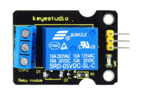
This single relay module can be used in interactive projects. This module uses SONGLE 5v high-quality relay. It can also be used to control lighting, electrical and other equipment. The modular design makes it easy to expand with the Arduino board (not included). The | This single relay module can be used in interactive projects. It is active HIGH level. This module uses SONGLE 5v high-quality relay. <br> | ||
It can also be used to control lighting, electrical and other equipment. <br> | |||
The modular design makes it easy to expand with the Arduino board (not included). The relay output is by a light-emitting diode. It can be controlled through digital IO port, such as solenoid valves, lamps, motors and other high current or high voltage devices. | |||
<br>[[File:Ks0011.png|500px|frameless|thumb]]<br> | |||
<br> | |||
==Specification== | ==Specification== | ||
*Type: Digital | *Type: Digital | ||
| Line 15: | Line 17: | ||
*Maximum switching power: AC1200VA DC240W (NO) AC625VA DC120W (NC) | *Maximum switching power: AC1200VA DC240W (NO) AC625VA DC120W (NC) | ||
*Contact action time: 10ms | *Contact action time: 10ms | ||
<br> | |||
==Connection Diagram == | |||
Firstly you need to prepare the following parts by yourself before testing. | |||
* Arduino Board*1 | |||
* Single relay module*1 | |||
* LED module *1 | |||
* USB Cable*1 | |||
* Jumper Wire*8 | |||
<br>[[File:Ks0011-1.png|500px|frameless|thumb]]<br> | |||
<br>[[File: | |||
==Sample Code== | <br> | ||
== Sample Code == | |||
Copy and paste the code below to Arduino software. | |||
<pre> | <pre> | ||
int Relay = 8; | |||
void setup() | |||
{ | { | ||
pinMode(13, OUTPUT); //Set Pin13 as output | |||
digitalWrite(13, HIGH); //Set Pin13 High | |||
pinMode(Relay, OUTPUT); //Set Pin3 as output | |||
} | } | ||
void loop() | void loop() | ||
{ | { | ||
digitalWrite(Relay, HIGH); //Turn off relay | |||
delay(2000); | |||
digitalWrite(Relay, LOW); //Turn on relay | |||
delay(2000); | |||
} | } | ||
</pre> | </pre> | ||
== | <br> | ||
http:// | == Test Result == | ||
This relay module is active HIGH level. <br> | |||
Wire it up well, powered up, then upload the above code to the board.<br> | |||
You will see the relay is turned on(ON connected, NC disconnected)for two seconds, then turned off for two seconds(NC closed,ON disconnected), repeatedly and circularly.<br> | |||
When the relay is turned on, external LED is on. If relay is turned off, external LED is off. | |||
<br>[[File:Ks0011-2.png|600px|frameless|thumb]]<br> | |||
<br> | |||
==Resources == | |||
'''Video'''<br> | |||
http://video.keyestudio.com/ks0011/ | |||
'''Datasheet and Code''' <br> | |||
https://fs.keyestudio.com/KS0011 | |||
<br> | |||
==Buy from == | |||
*[https://www.keyestudio.com/free-shipping-keyestudio-single-5v-relay-module-compatible-with-arduino-uno-r3-mega-p0195-p0195.html Official website] | |||
*[https://www.aliexpress.com/store/product/5V-One-1-channel-relay-module-Board-Shield-For-PIC-AVR-DSP-ARM-Arduino-MCU/1452162_2053019063.html?spm=2114.12010615.8148356.6.51395ee2oxGsxQ On Aliexpress] | |||
[[ | [[Category: Module]] | ||
Latest revision as of 10:10, 8 January 2021
Introduction
This single relay module can be used in interactive projects. It is active HIGH level. This module uses SONGLE 5v high-quality relay.
It can also be used to control lighting, electrical and other equipment.
The modular design makes it easy to expand with the Arduino board (not included). The relay output is by a light-emitting diode. It can be controlled through digital IO port, such as solenoid valves, lamps, motors and other high current or high voltage devices.

Specification
- Type: Digital
- Rated current: 10A (NO) 5A (NC)
- Maximum switching voltage: 150VAC 24VDC
- Digital interface
- Control signal: TTL level
- Rated load: 8A 150VAC (NO) 10A 24VDC (NO), 5A 250VAC (NO/NC) 5A 24VDC (NO/NC)
- Maximum switching power: AC1200VA DC240W (NO) AC625VA DC120W (NC)
- Contact action time: 10ms
Connection Diagram
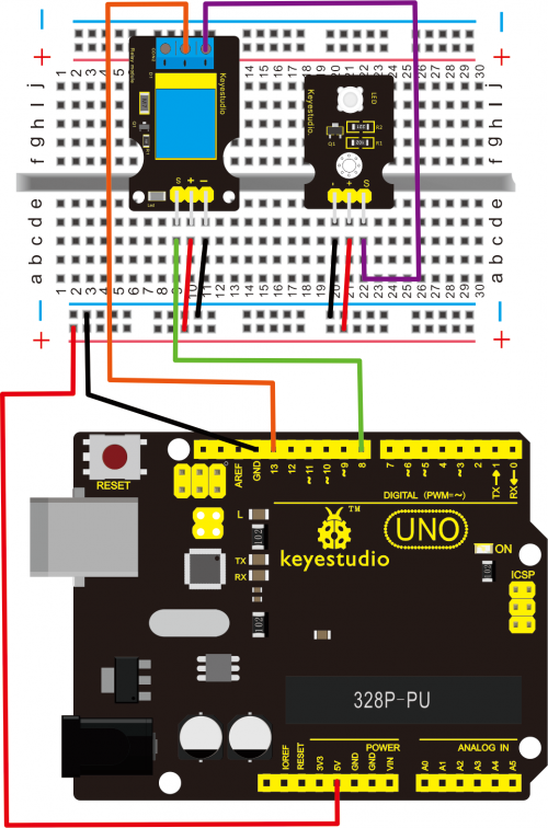
Firstly you need to prepare the following parts by yourself before testing.
- Arduino Board*1
- Single relay module*1
- LED module *1
- USB Cable*1
- Jumper Wire*8
Sample Code
Copy and paste the code below to Arduino software.
int Relay = 8;
  void setup()
{
  pinMode(13, OUTPUT);         //Set Pin13 as output
  digitalWrite(13, HIGH);     //Set Pin13 High
  pinMode(Relay, OUTPUT);     //Set Pin3 as output
}
void loop()
{
          digitalWrite(Relay, HIGH);   //Turn off relay
          delay(2000);
          digitalWrite(Relay, LOW);    //Turn on relay
          delay(2000);
}
Test Result
This relay module is active HIGH level.
Wire it up well, powered up, then upload the above code to the board.
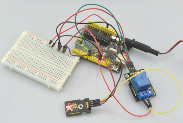
You will see the relay is turned on(ON connected, NC disconnected)for two seconds, then turned off for two seconds(NC closed,ON disconnected), repeatedly and circularly.
When the relay is turned on, external LED is on. If relay is turned off, external LED is off.

Resources
Video
http://video.keyestudio.com/ks0011/
Datasheet and Code
https://fs.keyestudio.com/KS0011
