KS0498 Keyestudio MEGA 2560 R3 Development Board(Compatible Arduino): Difference between revisions
Keyestudio (talk | contribs) |
Keyestudio (talk | contribs) |
||
| (15 intermediate revisions by the same user not shown) | |||
| Line 181: | Line 181: | ||
5. IIC communication: D20 (SDA); D21 (SCL). Support TWI communication using the Wire library. | 5. IIC communication: D20 (SDA); D21 (SCL). Support TWI communication using the Wire library. | ||
== | |||
== Windows System == | |||
=== Installing Arduino IDE === | === Installing Arduino IDE === | ||
When | When getting this control board, we need to install Arduino IDE | ||
Enter the website https://www.arduino.cc/, click [[File:0173--1.png|500px|frameless|thumb]] and [[File:0173--2.png|500px|frameless|thumb]] | |||
https://www.arduino.cc/ | |||
<br>[[File:0173--3.png|500px|frameless|thumb]]<br> | |||
Select the version you want to download, the latest version could be downloaded. | |||
<br>[[File:0173--4.png|500px|frameless|thumb]]<br> | |||
Alternatively, you could select previous release. | |||
In this project, we use 1.8.12 version. | |||
<br>[[File:0173--5.png|500px|frameless|thumb]]<br> | |||
Click[[File:KS0173----13.png|500px|frameless|thumb]] to view the below page | |||
<br>[[File:0173--8.png|500px|frameless|thumb]]<br> | |||
Click [[File:0173--6.png|500px|frameless|thumb]] to download an installer of Arduino 1.8.12 version,which needs to be installed manually. When you tap [[File:0173--7.png|500px|frameless|thumb]],a zip file of Arduino 1.8.12 version will be directly downloaded, and you only need to unzip it to finish installation. | |||
<br>[[File: | <br>[[File:0497=21.png|500px|frameless|thumb]]<br> | ||
Click [[File:0173--9.png|500px|frameless|thumb]]icon to download Arduino IDE. | |||
=== Installing driver === | === Installing driver === | ||
Let’s install the driver of Keyestudio MEGA 2560 R3 Development Board.. The USB-TTL chip on 2560 R3 Development Board adopts CP2102 serial chip. The driver program of this chip is included in Arduino 1.8 version and above, which is convenient. Plug on USB port of board, the computer can recognize the hardware and automatically install the driver of CP2102. | Let’s install the driver of Keyestudio MEGA 2560 R3 Development Board.. The USB-TTL chip on 2560 R3 Development Board adopts CP2102 serial chip. The driver program of this chip is included in Arduino 1.8 version and above, which is convenient. Plug on USB port of board, the computer can recognize the hardware and automatically install the driver of CP2102. | ||
<big> | |||
<span style=color:red>'''Note: If the version of Arduino IDE you download is below 1.8, you need to download the driver of CP2102.'''</span></big> | |||
</big>'''Download the driver of CP2102''':</big> | |||
</big><span style=color:red>'''https://fs.keyestudio.com/CP2102-WIN'''</span></big> | |||
If install unsuccessfully, or you intend to install manually, open the device manager of computer. Right click Computer----- Properties----- Device Manager. | If install unsuccessfully, or you intend to install manually, open the device manager of computer. Right click Computer----- Properties----- Device Manager. | ||
| Line 258: | Line 276: | ||
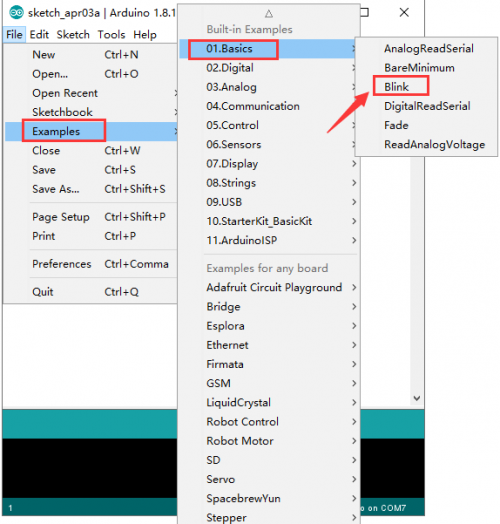
Open the file to select Example, choose BLINK from BASIC, as shown below: | Open the file to select Example, choose BLINK from BASIC, as shown below: | ||
<br>[[Image:048610png.png|500px|frameless]]<br> | <br>[[Image:048610png.png|500px|frameless]]<br> | ||
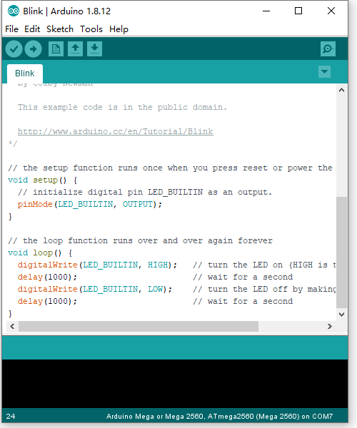
<br>[[Image:0498-----7.png|500px|frameless]]<br> | |||
<br>[[Image: | |||
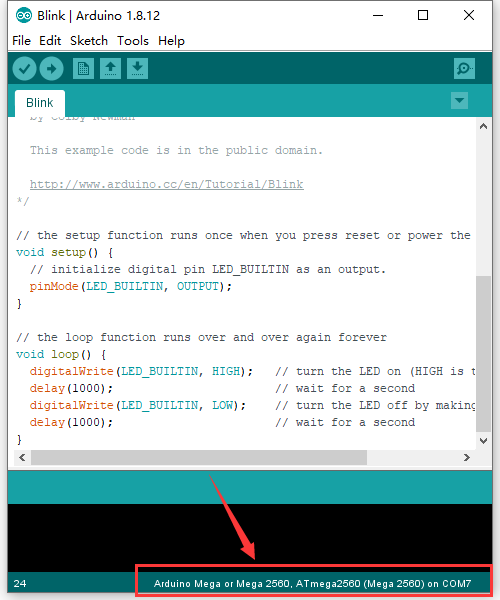
Set board and COM port, the corresponding board and COM port are shown on the lower right of IDE. | Set board and COM port, the corresponding board and COM port are shown on the lower right of IDE. | ||
<br>[[Image: | <br>[[Image:0498-----4.png|500px|frameless]]<br> | ||
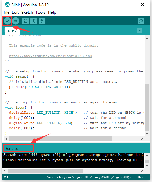
Click [[Image:0486-20.png|50px|frameless]] to start compiling the program, check errors. | Click [[Image:0486-20.png|50px|frameless]] to start compiling the program, check errors. | ||
<br>[[Image: | <br>[[Image:0498-----5.png|500px|frameless]]<br> | ||
Click [[Image:0486-23.png|50px|frameless]]to upload the program, upload successfully. | Click [[Image:0486-23.png|50px|frameless]]to upload the program, upload successfully. | ||
<br>[[Image: | <br>[[Image:0498-----6.png|500px|frameless]]<br> | ||
Upload the program successfully, the onboard LED lights on for 1s, lights off for 1s. Congratulation, you finish the first program. | Upload the program successfully, the onboard LED lights on for 1s, lights off for 1s. Congratulation, you finish the first program. | ||
== MAC System == | |||
=== Install Arduino IDE on MAC System === | |||
The installation instruction is as same as the chapter 5.1, as shown below: | |||
<br>[[Image:图片8883.png|500px|frameless]]<br> | |||
=== Download the Driver of CP2102 === | |||
https://fs.keyestudio.com/CP2102-MAC | |||
=== How to Install the Driver of CP2102 === | |||
https://wiki.keyestudio.com/How_to_Install_the_Driver_of_CP2102_on_MAC_System | |||
=== Arduino IDE Setting === | |||
The setting method is as same as the chapter 5.3 except from COM port, as shown below. | |||
<br>[[Image:0497=图片8.png|500px|frameless]]<br> | |||
== Resources == | == Resources == | ||
https://fs.keyestudio.com/KS0498 | |||
Latest revision as of 10:03, 3 March 2021
Description
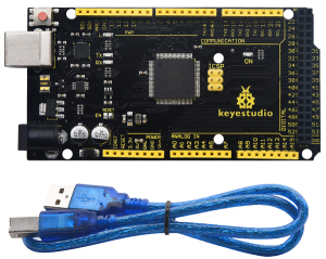
Keyestudio Mega 2560 R3 is a microcontroller board based on the ATMEGA2560-16AU , fully compatible with ARDUINO MEGA 2560 R3.
It has 54 digital input/output pins (of which 15 can be used as PWM outputs), 16 analog inputs, 4 UARTs (hardware serial ports), a 16 MHz crystal oscillator, a USB connection, a power jack, 1 ICSP header, and a reset button.
The built-in ICSP port can burn the firmware for ATMEGA2560-16AU directly. This chip is burnt the firmware well before leaving the factory, therefore, we hardly use it. We can power on by USB wire, DC head and Vin GND pins.
To facilitate wiring, a 0.5 m USB wire is provided for you.
Specification
- Microcontroller: ATMEGA2560-16AU
- USB serial chip:CP2102
- Operating Voltage: 5V
- Input Voltage (recommended):DC 7-12V
- Digital I/O Pins: 54 (D0-D53)
- PWM Digital I/O Pins:15(D2-D13 D44-D46)
- Analog Input Pins: 16(A0-A15)
- DC Current per I/O Pin: 20 mA
- DC Current for 3.3V Pin: 50 mA
- Flash Memory: 256 KB of which 8 KB used by bootloader
- SRAM: 8 KB
- EEPROM: 4 KB
- Clock Speed: 16 MHz
- LED_BUILTIN:D13
Element and Pin Interfaces:
Here is an explanation of what every element and interface of the board does:
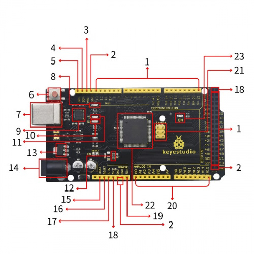

|
Digital I/O
Arduino MEGA has 54 digital input/output pins (of which 15 can be used as PWM outputs). These pins can be configured as digital input pin to read the logic value (0 or 1). Or used as digital output pin to drive different modules like LED, relay, etc. |

|
GND
Ground pins |

|
AREF
Reference voltage (0-5V) for analog inputs. Used with analogReference(). Configures the reference voltage used for analog input (i.e. the value used as the top of the input range). |

|
SDA
IIC communication pin |

|
SCL
IIC communication pin |

|
RESET Button
You can reset your Arduino board |

|
USB Connection
Arduino board can be powered via USB connector. |

|
D13 LED
There is a built-in LED driven by digital pin 13. When the pin is HIGH value, the LED is on, when the pin is LOW, it's off. |

|
CP2102
USB to serial chip, can convert the USB signal into serial port signal. |

|
TX LED
Onboard you can find the label: TX (transmit) |

|
RX LED
Onboard you can find the label: RX(receive ) |

|
Crystal Oscillator
How does Arduino calculate time? by using a crystal oscillator. |

|
Voltage Regulator
To control the voltage provided to the Arduino board, as well as to stabilize the DC voltage used by the processor and other components. |

|
DC Power Jack
Arduino board can be supplied with an external power DC7-12V from the DC power jack. |

|
IOREF
This pin on the board provides the voltage reference with which the microcontroller operates. A properly configured shield can read the IOREF pin voltage and select the appropriate power source or enable voltage translators on the outputs for working with the 5V or 3.3V. |

|
Power Pin 3V3
A 3.3 volt supply generated by the on-board regulator. Maximum current draw is 50 mA. |

|
RESET Header
Connect an external button to reset the board. The function is the same as reset button. |

|
Power Pin 5V
Provides 5V output voltage |

|
Vin
You can supply an external power input DC7-12V through this pin to Arduino board. |

|
Analog Pins
Onboard has 16 analog inputs, labeled A0 to A15. |

|
ICSP (In-Circuit Serial Programming) Header
the AVR, an Arduino micro-program header consisting of MOSI, MISO, SCK, RESET, VCC, and GND. |

|
Microcontroller
Each Arduino board has its own microcontroller. You can regard it as the brain of your board. |

|
Power LED Indicator
Powering the Arduino, LED on means that your circuit board is correctly powered on. If LED is off, connection is wrong. |
Specialized Functions of Some Pins:
1. Serial Communication: D0 (RX0) and D1 (TX1); Serial 1: D19 (RX1) and D18 (TX1); Serial 2: D17 (RX2) and D16 (TX2); Serial 3: D15 (RX3) and D14 (TX3). Used to receive (RX) and transmit (TX) TTL serial data. Pins 0 and 1 are also connected to the corresponding pins of the CP2102 USB-to-TTL Serial chip.
2. PWM Pins (Pulse-Width Modulation): D2 to D13, and D44 to D46. Provide 8-bit PWM output with the analogWrite() function.
3. External Interrupts: D2 (interrupt 0), D3 (interrupt 1), D18 (interrupt 5), D19 (interrupt 4), D20 (interrupt 3), and D21 (interrupt 2). These pins can be configured to trigger an interrupt on a low level, a rising or falling edge, or a change in level. See the attachInterrupt() function for details.
4. SPI communication: D53 (SS), D52 (SCK), D51 (MOSI), D50 (MISO). These pins support SPI communication using theSPI library. The SPI pins are also broken out on the ICSP header, which is physically compatible with the Arduino Uno.
5. IIC communication: D20 (SDA); D21 (SCL). Support TWI communication using the Wire library.
Windows System
Installing Arduino IDE
When getting this control board, we need to install Arduino IDE
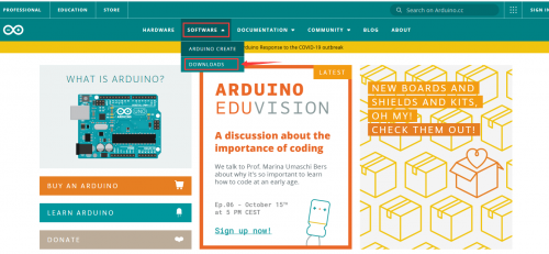
Enter the website https://www.arduino.cc/, click ![]() and
and ![]()
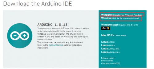
Select the version you want to download, the latest version could be downloaded.
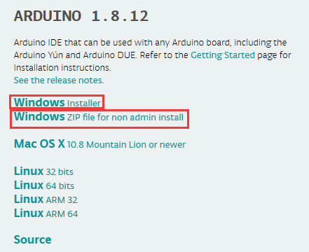
Alternatively, you could select previous release. In this project, we use 1.8.12 version.
Click ![]() to download an installer of Arduino 1.8.12 version,which needs to be installed manually. When you tap
to download an installer of Arduino 1.8.12 version,which needs to be installed manually. When you tap ![]() ,a zip file of Arduino 1.8.12 version will be directly downloaded, and you only need to unzip it to finish installation.
,a zip file of Arduino 1.8.12 version will be directly downloaded, and you only need to unzip it to finish installation.
Click  icon to download Arduino IDE.
Installing driver
Let’s install the driver of Keyestudio MEGA 2560 R3 Development Board.. The USB-TTL chip on 2560 R3 Development Board adopts CP2102 serial chip. The driver program of this chip is included in Arduino 1.8 version and above, which is convenient. Plug on USB port of board, the computer can recognize the hardware and automatically install the driver of CP2102.
Note: If the version of Arduino IDE you download is below 1.8, you need to download the driver of CP2102.
Download the driver of CP2102: https://fs.keyestudio.com/CP2102-WIN
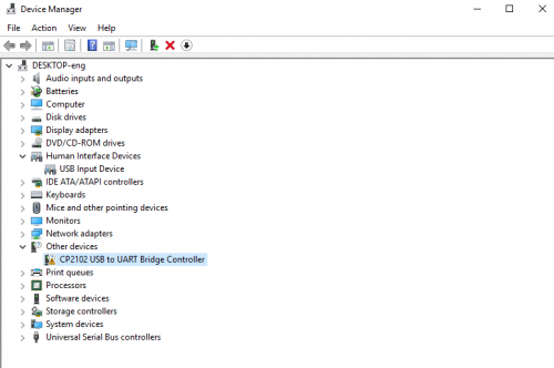
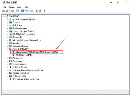
If install unsuccessfully, or you intend to install manually, open the device manager of computer. Right click Computer----- Properties----- Device Manager.
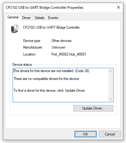
There is a yellow exclamation mark on the page, which implies installing the driver of CP2102 unsuccessfully. Then we double click the hardware and update the driver.
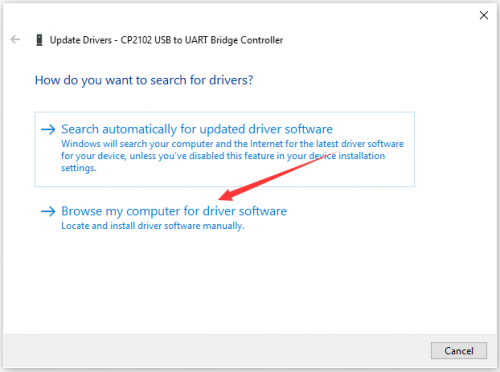
Click “OK” to enter the following page, click “browse my computer for updated driver software”, find out the installed or downloaded ARDUINO software. As shown below:
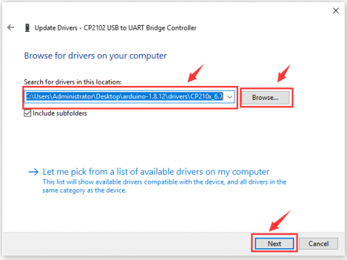
There is a DRIVERS folder in Arduino software installed package(![]() ), open driver folder and you can see the driver of CP210X series chips.
), open driver folder and you can see the driver of CP210X series chips.
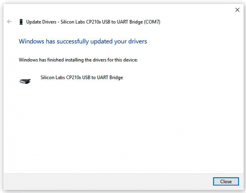
We click “Browse”, then find out the driver folder, or you could enter “driver” to search in rectangular box, then click “next”, the driver will be installed successfully. (I place Arduino software folder on the desktop, you could follow my way)
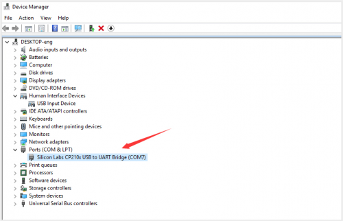
Open device manager, we will find the yellow exclamation mark disappear. The driver of CP2102 is installed successfully.
Arduino IDE Setting
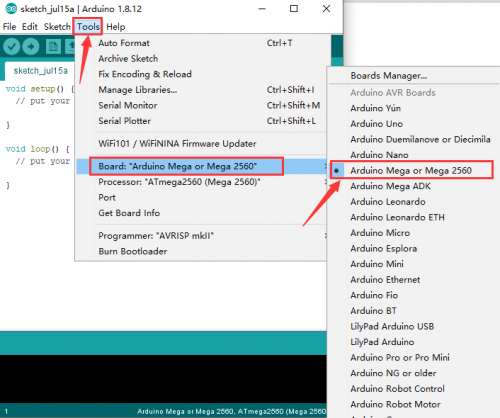
To avoid the errors when uploading the program to the board, you need to select the correct Arduino board that matches the board connected to your computer. Then come back to the Arduino software, you should click Tools→Board, select the board. (as shown below)
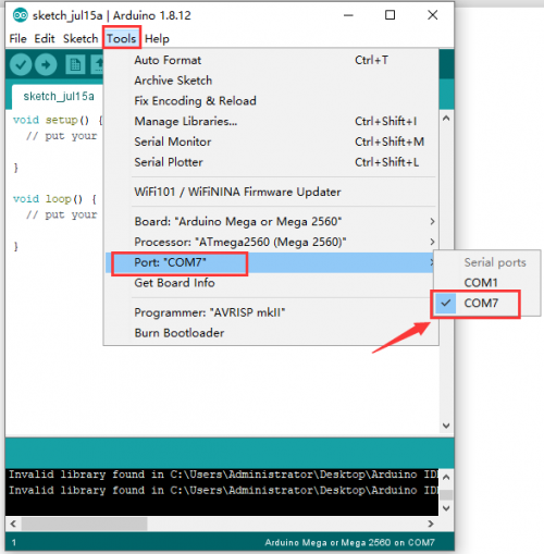
Then select the correct COM port (you can see the corresponding COM port after the driver is successfully installed)
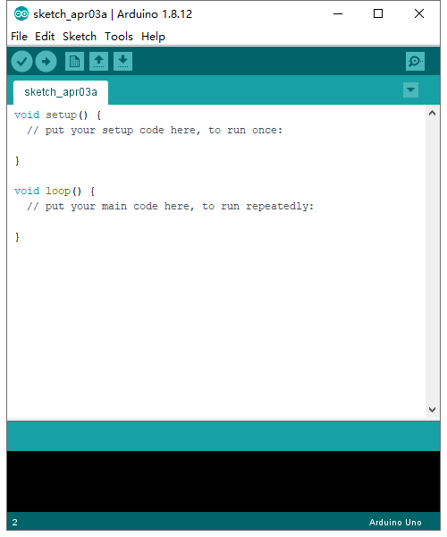
Before uploading the program to the board, let’s demonstrate the function of each symbol in the Arduino IDE toolbar.
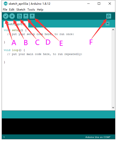
A- Used to verify whether there is any compiling mistakes or not. B- Used to upload the sketch to your Arduino board. C- Used to create shortcut window of a new sketch. D- Used to directly open an example sketch. E- Used to save the sketch. F- Used to send the serial data received from board to the serial monitor.
Start your first program
Open the file to select Example, choose BLINK from BASIC, as shown below:
Set board and COM port, the corresponding board and COM port are shown on the lower right of IDE.
Click ![]() to start compiling the program, check errors.
to start compiling the program, check errors.
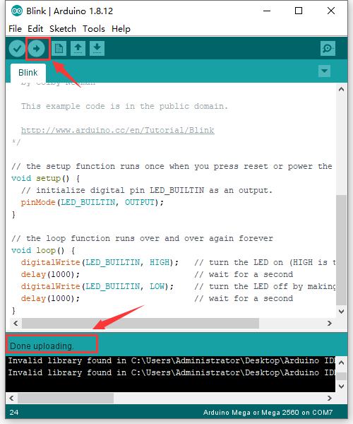
Click ![]() to upload the program, upload successfully.
to upload the program, upload successfully.
Upload the program successfully, the onboard LED lights on for 1s, lights off for 1s. Congratulation, you finish the first program.
MAC System
Install Arduino IDE on MAC System
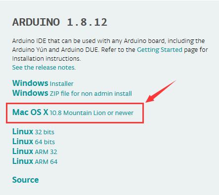
The installation instruction is as same as the chapter 5.1, as shown below:
Download the Driver of CP2102
https://fs.keyestudio.com/CP2102-MAC
How to Install the Driver of CP2102
https://wiki.keyestudio.com/How_to_Install_the_Driver_of_CP2102_on_MAC_System
Arduino IDE Setting
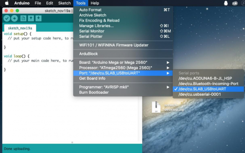
The setting method is as same as the chapter 5.3 except from COM port, as shown below.
