KS0517 Keyestudio DS1302 Clock Sensor(Black and Eco-friendly): Difference between revisions
Keyestudio (talk | contribs) (Created blank page) |
Keyestudio (talk | contribs) |
||
| (10 intermediate revisions by the same user not shown) | |||
| Line 1: | Line 1: | ||
<br>[[File:Ks0517-1.png|400px|right|frameless|thumb]]<br> | |||
=='''Introduction'''== | |||
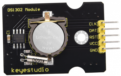
With a BS-1220 battery holder and a CR1220 battery, Keyestudio DS1302 clock sensor adopts DS1302 clock chip, which is mainly used for power-off timing.<br> | |||
DS1302, a trickle charge clock chip rolled out by DALLAS, is inclusive of a real-time clock/calendar and 31 bytes of static RAM. It communicates with the microcontroller through the serial interface. <br> | |||
The real-time clock/calendar circuit provides information about seconds, minutes, hours, days, weeks, months, and years. In addition, the number of days in a month and ones of a leap year can be adjusted automatically. <br> | |||
The clock operation uses 24 or 12 hour format through AM/PM indication.<br> | |||
The DS1302 can communicate with the single-chip microcomputer through the synchronous serial way and only three ports needed which are RST reset , I/O data line and SCLK serial clock. <br> | |||
The read and write data of the clock/RAM is communicated in a byte or over 31 bytes. Its power consumption is very low when working, thereby, the power is less than 1mW when keeping data and clock information.<br> | |||
Meanwhile, a positioning hole of the module contributes to fix it on the other devices.<br> | |||
== '''Specification:''' == | |||
* Working voltage: DC 5V | |||
* Working current: 60mA | |||
* Maximum power: 0.3A | |||
* Working temperature: -25℃-65℃ | |||
* Interface: 5pin header interface with 2.54mm pitch | |||
* Positioning hole: 3mm in diameter | |||
* Size: 50*28mm | |||
* Weight: 5.8g | |||
* The backup battery is CR1220 and non-rechargeable | |||
* Voltage:3V | |||
* Current: 40mAh | |||
* The theoretical data can be retained for more than 1 year | |||
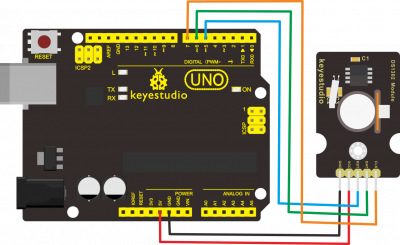
== '''Hook-up Diagram''' == | |||
<br>[[File:Ks0517-2.png|400px|frameless|thumb]]<br> | |||
== '''Test Code''' == | |||
<pre> | |||
#include <stdio.h> | |||
#include <string.h> | |||
#include <DS1302.h> | |||
/* Set the appropriate digital I/O pin connections */ | |||
uint8_t CE_PIN = 5; | |||
uint8_t IO_PIN = 6; | |||
uint8_t SCLK_PIN = 7; | |||
/* Create buffers */ | |||
char buf[50]; | |||
char day[10]; | |||
/* Create a DS1302 object */ | |||
DS1302 rtc(CE_PIN, IO_PIN, SCLK_PIN); | |||
void print_time() | |||
{ | |||
/* Get the current time and date from the chip */ | |||
Time t = rtc.time(); | |||
/* Name the day of the week */ | |||
memset(day, 0, sizeof(day)); /* clear day buffer */ | |||
switch (t.day) { | |||
case 1: | |||
strcpy(day, "Sunday"); | |||
break; | |||
case 2: | |||
strcpy(day, "Monday"); | |||
break; | |||
case 3: | |||
strcpy(day, "Tuesday"); | |||
break; | |||
case 4: | |||
strcpy(day, "Wednesday"); | |||
break; | |||
case 5: | |||
strcpy(day, "Thursday"); | |||
break; | |||
case 6: | |||
strcpy(day, "Friday"); | |||
break; | |||
case 7: | |||
strcpy(day, "Saturday"); | |||
break; | |||
} | |||
snprintf(buf, sizeof(buf), "%s %04d-%02d-%02d %02d:%02d:%02d", | |||
day, | |||
t.yr, t.mon, t.date, | |||
t.hr, t.min, t.sec); | |||
Serial.println(buf); | |||
} | |||
void setup() | |||
{ Serial.begin(9600); | |||
rtc.write_protect(false); | |||
rtc.halt(false); | |||
Time t(2020, 8, 5, 11,12,13,4); | |||
rtc.time(t);} | |||
void loop() | |||
{ print_time(); | |||
delay(1000);} | |||
</pre> | |||
== '''Test Result''' == | |||
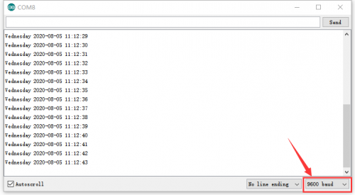
Wire up the components according to the above figure, burn the code and power on. The current time and date are displayed on the serial monitor, as shown below. | |||
<br>[[File:Ks0517-3.png|500px|frameless|thumb]]<br> | |||
== '''Resource''' == | |||
https://fs.keyestudio.com/KS0517 | |||
Latest revision as of 09:04, 25 August 2020
Introduction
With a BS-1220 battery holder and a CR1220 battery, Keyestudio DS1302 clock sensor adopts DS1302 clock chip, which is mainly used for power-off timing.
DS1302, a trickle charge clock chip rolled out by DALLAS, is inclusive of a real-time clock/calendar and 31 bytes of static RAM. It communicates with the microcontroller through the serial interface.
The real-time clock/calendar circuit provides information about seconds, minutes, hours, days, weeks, months, and years. In addition, the number of days in a month and ones of a leap year can be adjusted automatically.
The clock operation uses 24 or 12 hour format through AM/PM indication.
The DS1302 can communicate with the single-chip microcomputer through the synchronous serial way and only three ports needed which are RST reset , I/O data line and SCLK serial clock.
The read and write data of the clock/RAM is communicated in a byte or over 31 bytes. Its power consumption is very low when working, thereby, the power is less than 1mW when keeping data and clock information.
Meanwhile, a positioning hole of the module contributes to fix it on the other devices.
Specification:
- Working voltage: DC 5V
- Working current: 60mA
- Maximum power: 0.3A
- Working temperature: -25℃-65℃
- Interface: 5pin header interface with 2.54mm pitch
- Positioning hole: 3mm in diameter
- Size: 50*28mm
- Weight: 5.8g
- The backup battery is CR1220 and non-rechargeable
- Voltage:3V
- Current: 40mAh
- The theoretical data can be retained for more than 1 year
Hook-up Diagram
Test Code
#include <stdio.h>
#include <string.h>
#include <DS1302.h>

/* Set the appropriate digital I/O pin connections */
uint8_t CE_PIN   = 5;
uint8_t IO_PIN   = 6;
uint8_t SCLK_PIN = 7;

/* Create buffers */
char buf[50];
char day[10];

/* Create a DS1302 object */
DS1302 rtc(CE_PIN, IO_PIN, SCLK_PIN);

void print_time()
{
  /* Get the current time and date from the chip */
  Time t = rtc.time();

  /* Name the day of the week */
  memset(day, 0, sizeof(day));  /* clear day buffer */

  switch (t.day) {
    case 1:
      strcpy(day, "Sunday");
      break;
    case 2:
      strcpy(day, "Monday");
      break;
    case 3:
      strcpy(day, "Tuesday");
      break;
    case 4:
      strcpy(day, "Wednesday");
      break;
    case 5:
      strcpy(day, "Thursday");
      break;
    case 6:
      strcpy(day, "Friday");
      break;
    case 7:
      strcpy(day, "Saturday");
      break;
  }
  snprintf(buf, sizeof(buf), "%s %04d-%02d-%02d %02d:%02d:%02d",
           day,
           t.yr, t.mon, t.date,
           t.hr, t.min, t.sec);
  Serial.println(buf);
}
void setup()
{  Serial.begin(9600);
  rtc.write_protect(false);
  rtc.halt(false);
  Time t(2020, 8, 5, 11,12,13,4);
  rtc.time(t);}
void loop()
{ print_time();
  delay(1000);}
Test Result
Wire up the components according to the above figure, burn the code and power on. The current time and date are displayed on the serial monitor, as shown below.


