Ks0287 keyestudio SIM5320E 3G Module (Black): Difference between revisions
Keyestudio (talk | contribs) |
Keyestudio (talk | contribs) |
||
| (23 intermediate revisions by the same user not shown) | |||
| Line 1: | Line 1: | ||
== keyestudio SIM5320E 3G Module | <br> | ||
== keyestudio SIM5320E 3G Module == | |||
<br>[[File:Ks0287.png|500px|frameless|thumb]]<br> | <br>[[File:Ks0287.png|500px|frameless|thumb]]<br> | ||
<br> | |||
== Description == | == Description == | ||
keyestudio SIM5320E 3G module is a mobile phone module, it can be used for GPRS data transmission, supporting both Mobile and Unicom. This module has the function of GPS positioning, with the features of powerful functions and less external circuits,etc. When registering the network and RF multi-slot sending,the current consumption peak may reach 2A, which will inevitably lead to voltage sags, so the power system generally requires more than 2A current supply capability. | keyestudio SIM5320E 3G module is a mobile phone module, it can be used for GPRS data transmission, supporting both Mobile and Unicom. <br> | ||
This module has the function of GPS positioning, with the features of powerful functions and less external circuits,etc. <br> | |||
When registering the network and RF multi-slot sending,the current consumption peak may reach 2A, which will inevitably lead to voltage sags, so the power system generally requires more than 2A current supply capability. | |||
<br> | |||
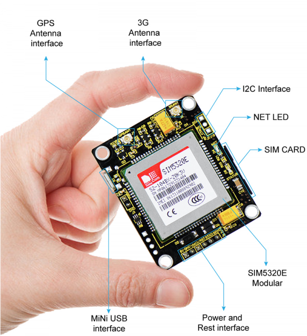
==Interface Explanation == | ==Interface Explanation == | ||
* Power Supply: DC 5V 2A or above. | * Power Supply: DC 5V 2A or above. | ||
| Line 17: | Line 22: | ||
* Indicator LEDs: one LED is used to indicate the working status of the module; another 0603 LED is used to indicate the network status. | * Indicator LEDs: one LED is used to indicate the working status of the module; another 0603 LED is used to indicate the network status. | ||
<br>[[File:KS0287.png|600px|frameless|thumb]]<br> | |||
<br> | |||
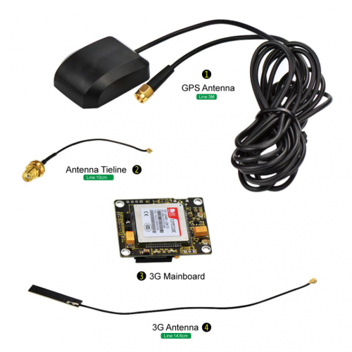
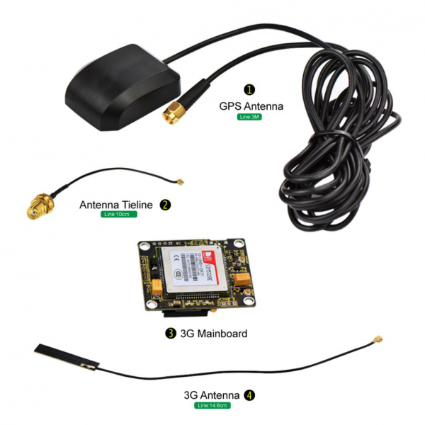
== Shipping List == | |||
<br>[[File:Ks0287.png|600px|frameless|thumb]]<br> | |||
<br> | |||
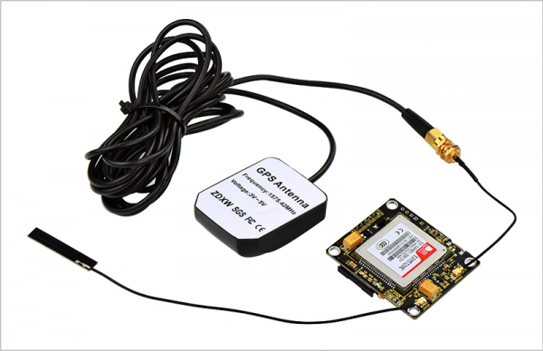
== Example Connection== | |||
<br>[[File:KS0287-1.png|600px|frameless|thumb]]<br> | |||
<br> | |||
==Preparation == | ==Preparation == | ||
1、Insert the SIM card <br> | 1、Insert the SIM card <br> | ||
| Line 30: | Line 46: | ||
* Diagnostics COM port:used for debugging, grab the log information of module. | * Diagnostics COM port:used for debugging, grab the log information of module. | ||
* Ethernet Adapter:not supporting. | * Ethernet Adapter:not supporting. | ||
<br> | |||
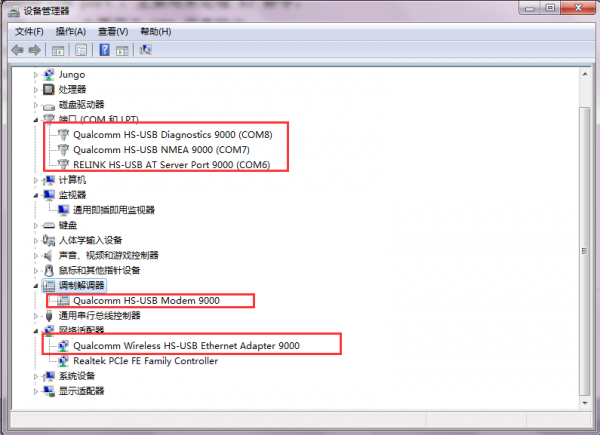
1)'''Windows 7: 5 COM ports mapping shown in the below figure:''' | 1)'''Windows 7: 5 COM ports mapping shown in the below figure:''' | ||
<br>[[File:Ks0287-1.png| | <br>[[File:Ks0287-1.png|600px|frameless|thumb]]<br> | ||
2)'''Linux: corresponding COM ports, such as:''' | 2)'''Linux: corresponding COM ports, such as:''' | ||
| Line 50: | Line 66: | ||
"Index"=dword:X | "Index"=dword:X | ||
"FriendlyName"="SimTech HS-USB Modem 9000" | "FriendlyName"="SimTech HS-USB Modem 9000" | ||
<br> | |||
== COM Port Connection == | == COM Port Connection == | ||
'''1>.''' Send the AT command through the serial port on the J6 pin. Connect the RX pin of TTL level to STXD of module; TX is connected to SRXD; GND is connected to GND. Open the serial debugging software. Select the current port, set the baud rate to 115200. Specific as shown below: | |||
<br>[[File:Ks0287-2.png|700px|frameless|thumb]]<br> | |||
<br> | |||
Set up well as the above figure, then open the serial port, in the string text field input AT, click Send, it will show AT OK. It means that the communication between the computer and the module is normal. <br> | |||
<br> | |||
'''2>.''' Communicate with the computer via the serial port on the USB interface. The settings are the same as the above figure except the COM port. The specific AT command port like [[File:Ks0287-3.png|600px|frameless|thumb]]<br> | |||
<br> | |||
== GPS Testing == | == GPS Testing == | ||
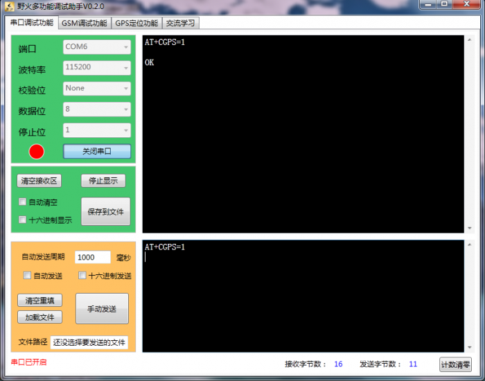
Before using the GPS function, you should first check whether the GPS function is enabled by using the AT command, or directly open the GPS function. Use AT + CGPS =1, getting feedback OK, as shown below, you can view the corresponding information through GPS software. | Before using the GPS function, you should first check whether the GPS function is enabled by using the AT command, or directly open the GPS function. Use AT + CGPS =1, getting feedback OK, as shown below, you can view the corresponding information through GPS software.<br> | ||
<br>[[File:Ks0287-4.png|700px|frameless|thumb]]<br> | |||
<br>[[File:Ks0287- | Select COM port like [[File:Ks0287-5.png|500px|frameless|thumb]] , set baud rate to 115200.<br> | ||
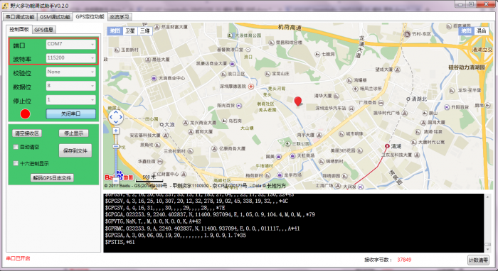
Setting well, open the serial port, you can see the related information about current positioning, including latitude, longitude, elevation and other information, as shown below. | |||
<br>[[File:Ks0287-6.png|700px|frameless|thumb]]<br> | |||
<br>[[File:Ks0287-7.png|700px|frameless|thumb]]<br> | |||
<br> | |||
== Calling Function == | == Calling Function == | ||
1、First,on the J9 of module, connect speakers to SPKM and SPKP, connect MIC to MICN and MICP. | 1、First,on the J9 of module, connect speakers to SPKM and SPKP, connect MIC to MICN and MICP.<br> | ||
Please refer to the corresponding circuit file like [[File:Ks0287-8.png|500px|frameless|thumb]] <br> | |||
<br>[[File:Ks0287-3-1.png|720px|frameless|thumb]]<br> | |||
<br>[[File:Ks0287- | <br>[[File:Ks0287-4-1.png|700px|frameless|thumb]]<br> | ||
<br>[[File:Ks0287- | |||
2、Connect to serial module via the serial port on J2, J6. RX pin is connected to STXD, TX to SRXD, GND to GND. Or directly connect to the computer via USB cable, | 2、Connect to serial module via the serial port on J2, J6. RX pin is connected to STXD, TX to SRXD, GND to GND. Or directly connect to the computer via USB cable, then set the baud rate 115200, open the serial port,[[File:Ks0287-11.png|600px|frameless|thumb]], you can use the AT command.<br> | ||
1> After registering the network, first pass the AT command AT + CSDVC = 3,0 (open SIM5320E speakerphone function). Specific settings please refer to AT command introduction. <br> | 1> After registering the network, first pass the AT command AT + CSDVC = 3,0 (open SIM5320E speakerphone function). Specific settings please refer to AT command introduction. <br> | ||
| Line 86: | Line 104: | ||
5> ATA // answer the call <br> | 5> ATA // answer the call <br> | ||
6> ATH // hang up the phone <br> | 6> ATH // hang up the phone <br> | ||
<br> | |||
== SMS Function == | == SMS Function == | ||
| Line 92: | Line 112: | ||
3> AT + CMGR = 10 // Read SMS <br> | 3> AT + CMGR = 10 // Read SMS <br> | ||
<br> | |||
== TCP/IP Function == | == TCP/IP Function == | ||
Before building TCP/IP connection, confirm the module has been registered the network and attach GPRS network. <br> | Before building TCP/IP connection, confirm the module has been registered the network and attach GPRS network. <br> | ||
<pre> | <pre> | ||
| Line 159: | Line 179: | ||
</pre> | </pre> | ||
<br> | |||
== Other commonly used AT command == | == Other commonly used AT command == | ||
The following examples are for reference only, more details please refer to the official SIM5320 instruction file. <br> | The following examples are for reference only, more details please refer to the official SIM5320 instruction file. <br> | ||
<br> | |||
=== 1. Network Registration === | |||
<pre> | <pre> | ||
AT+CPIN? | AT+CPIN? | ||
| Line 195: | Line 215: | ||
</pre> | </pre> | ||
<br> | |||
=== 2.Getting Network Time === | |||
<pre> | <pre> | ||
AT+CPSI? | AT+CPSI? | ||
| Line 210: | Line 231: | ||
</pre> | </pre> | ||
<br> | |||
=== 3.Voice Function === | |||
<pre> | <pre> | ||
setting the called number display | setting the called number display | ||
| Line 269: | Line 292: | ||
</pre> | </pre> | ||
<br> | |||
=== 4.SMS Function === | |||
<pre> | <pre> | ||
inquiry the storage capacity of short message inside SIM. | inquiry the storage capacity of short message inside SIM. | ||
| Line 340: | Line 365: | ||
</pre> | </pre> | ||
<br> | |||
=== 5.Data Transfer Function === | |||
<pre> | <pre> | ||
Before building TCP/IP connection, first confirm the module has been registered the network and attach GPRS network. | Before building TCP/IP connection, first confirm the module has been registered the network and attach GPRS network. | ||
| Line 404: | Line 431: | ||
</pre> | </pre> | ||
<br> | |||
=== 6.Audio Parameter Adjustment === | |||
<pre> | <pre> | ||
Echo Suppression | Echo Suppression | ||
| Line 439: | Line 468: | ||
</pre> | </pre> | ||
<br> | |||
===7.USB Audio Function === | |||
<pre> | <pre> | ||
AT+DSWITCH=1 // switch DBG mode to data mode | AT+DSWITCH=1 // switch DBG mode to data mode | ||
| Line 450: | Line 481: | ||
</pre> | </pre> | ||
<br> | |||
=== 8.Receive PC Side File === | |||
<pre> | <pre> | ||
AT+FSMEM | AT+FSMEM | ||
| Line 469: | Line 502: | ||
</pre> | </pre> | ||
<br> | |||
=== 9.MMS Function === | |||
<pre> | <pre> | ||
set the parameter | set the parameter | ||
| Line 522: | Line 557: | ||
</pre> | </pre> | ||
<br> | |||
=== 10.FTP Function === | |||
<pre> | <pre> | ||
set the parameter | set the parameter | ||
| Line 574: | Line 611: | ||
+CHTTPACT: REQUEST // wait the request back | +CHTTPACT: REQUEST // wait the request back | ||
</pre> | </pre> | ||
<br> | |||
== Documents == | == Documents == | ||
'''Related Tool:''' <br> | * '''Related Tool:''' <br> | ||
https:// | |||
https://fs.keyestudio.com/KS0287 | |||
<br> | |||
== Buy From == | == Buy From == | ||
*[https://www.keyestudio.com/keyestudio-sim5320e-3g-module-gsm-gprs-gps-modules-for-arduino-51-avr-mcu-p0357-p0357.html Official website ] | |||
*[https://www.aliexpress.com/store/product/keyestudio-SIM5320E-3G-Module-GSM-GPRS-GPS-Modules-for-Arduino-51-AVR-MCU/1452162_32846939101.html Shop on aliexpress] | |||
*[https://www.amazon.com/dp/B078RFVCM3 Shop on amazon] | |||
[[Category: Module]] | [[Category: Module]] | ||
Latest revision as of 09:36, 5 March 2021
keyestudio SIM5320E 3G Module
Description
keyestudio SIM5320E 3G module is a mobile phone module, it can be used for GPRS data transmission, supporting both Mobile and Unicom.
This module has the function of GPS positioning, with the features of powerful functions and less external circuits,etc.
When registering the network and RF multi-slot sending,the current consumption peak may reach 2A, which will inevitably lead to voltage sags, so the power system generally requires more than 2A current supply capability.
Interface Explanation
- Power Supply: DC 5V 2A or above.
- Communication Interface: a group of TTL-level serial port, compatible with 5V/3.3V microcontroller; with a USB interface, can be directly connected to the computer debugging.
- GPS Antenna Interface: a group of IPXmini antenna interface, the default connecting to active GPS antenna.
- GMS Antenna Interface: a group of IPXmini antenna interface, the default providing PCB antenna.
- SIM Card Interface: drawer type
- USB Interface: mini USB interface
- Voice Mike Interface: Lead out, the interface is a 2.54 * 4P single row pin form.
- Other Interfaces: a group of IIC interfaces, a group of interface can control the module’s opening and closing (the module default self-starting).
- Indicator LEDs: one LED is used to indicate the working status of the module; another 0603 LED is used to indicate the network status.
Shipping List
Example Connection
Preparation
1、Insert the SIM card
2、J2: power supply DC 5V 2A
3、3G ANT interface: connecting 3G antenna
4、GPS ANT interface: connecting GPS antenna
5、Connecting to MICRO USB interface.
Done drive installation, it will build communication between USB and system,5 ports
will be mapped on the system as follows:
- USB Modem COM port:used to dial-up networking.
- AT command COM port:used to process AT command.
- NMEA COM port:used for GPS information output.
- Diagnostics COM port:used for debugging, grab the log information of module.
- Ethernet Adapter:not supporting.
1)Windows 7: 5 COM ports mapping shown in the below figure:
2)Linux: corresponding COM ports, such as:
      Device file simcom’s composite device;
      ttyUSB0 diag interface;
      ttyUSB1 nmea interface;
      ttyUSB2 at interface;
      ttyUSB3 modem interface;
      ttyUSB4 Wireless Ethernet Adapter interface.
3)Wince: corresponding COM ports, such as(only map out 3 com ports,ranging 1-9):
      "Index"=dword:X
      "FriendlyName"="SimTech HS-USB NMEA 9000"
      "Index"=dword:X
      "FriendlyName"="SimTech HS-USB ATCOM 9000"
      "Index"=dword:X
      "FriendlyName"="SimTech HS-USB Modem 9000"
COM Port Connection
1>. Send the AT command through the serial port on the J6 pin. Connect the RX pin of TTL level to STXD of module; TX is connected to SRXD; GND is connected to GND. Open the serial debugging software. Select the current port, set the baud rate to 115200. Specific as shown below:
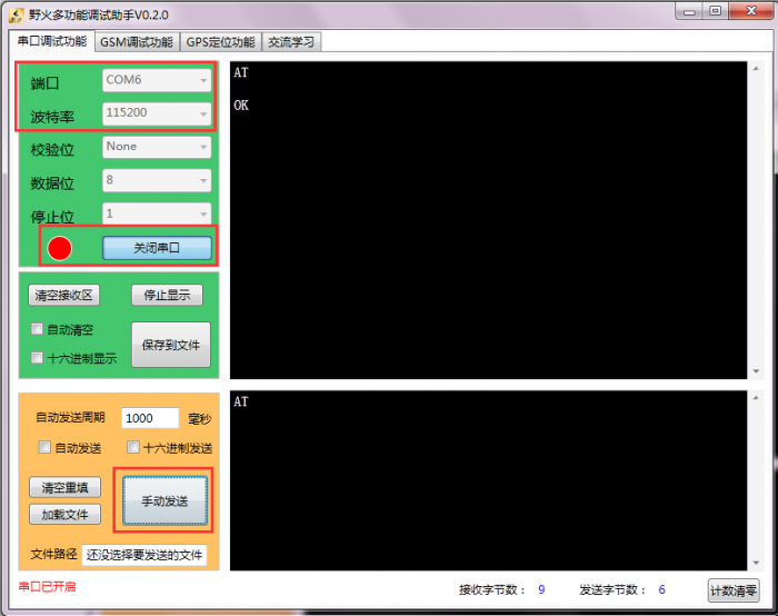
Set up well as the above figure, then open the serial port, in the string text field input AT, click Send, it will show AT OK. It means that the communication between the computer and the module is normal.
2>. Communicate with the computer via the serial port on the USB interface. The settings are the same as the above figure except the COM port. The specific AT command port like ![]()
GPS Testing
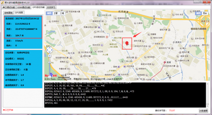
Before using the GPS function, you should first check whether the GPS function is enabled by using the AT command, or directly open the GPS function. Use AT + CGPS =1, getting feedback OK, as shown below, you can view the corresponding information through GPS software.
Select COM port like ![]() , set baud rate to 115200.
, set baud rate to 115200.
Setting well, open the serial port, you can see the related information about current positioning, including latitude, longitude, elevation and other information, as shown below.
Calling Function
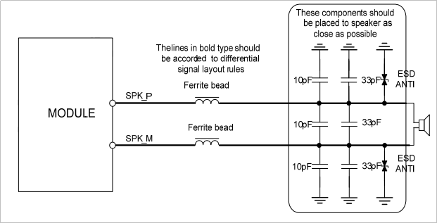
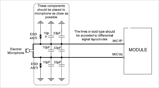
1、First,on the J9 of module, connect speakers to SPKM and SPKP, connect MIC to MICN and MICP.
Please refer to the corresponding circuit file like 
2、Connect to serial module via the serial port on J2, J6. RX pin is connected to STXD, TX to SRXD, GND to GND. Or directly connect to the computer via USB cable, then set the baud rate 115200, open the serial port,![]() , you can use the AT command.
, you can use the AT command.
1> After registering the network, first pass the AT command AT + CSDVC = 3,0 (open SIM5320E speakerphone function). Specific settings please refer to AT command introduction.
2> AT + COLP = 1 // Set to display the called number
3> AT + COLP = 1 // Set to display the caller ID
4> ATD32523094; / / make a call, the semicolon can not be less.
5> ATA // answer the call
6> ATH // hang up the phone
SMS Function
1> AT + CPMS? // Check the storage capacity of short message in the SIM card
2> AT + CNMI = 2,1 // Set a new SMS prompt function
3> AT + CMGR = 10 // Read SMS
TCP/IP Function
Before building TCP/IP connection, confirm the module has been registered the network and attach GPRS network.
//preparations as below
AT+CSQ
//signal quality inquiry
+CSQ: 18,99
OK
AT+CPIN?
// SIM card status inquiry
+CPIN: READY
OK
AT+CGATT?
+CGATT: 1//GPRS attachment inquiry
OK
AT+CGSOCKCONT=1,"IP","cmnet"
//set APN
OK
AT+CSOCKSETPN=1
//no modification
OK
AT+CIPMODE=0
//set as non-serialnet mode
OK
AT+NETOPEN
OK
+NETOPEN: 0
AT+IPADDR
//get the local IP address
+IPADDR: 10.119.116.22
OK
AT+CIPOPEN=0,"TCP","118.190.93.84",2317
//only support IP address, not supporting domain name.
OK
+CIPOPEN: 0,0//connecting successfully
AT+CIPSEND=0,5
//send 5 bytes content
>12345// The content is sent automatically for 5 bytes. If less than 5 bytes, the module will wait. Extra 5 bytes, its back bytes are automatically discarded.
OK
+CIPSEND: 0,5,5
AT+CIPSEND=0,
//Do not specify a fixed length.
>1234556 // After the content is input, enter a hexadecimal 1A, close the content to start sending
OK
+CIPSEND: 0,9,9//send successfully
AT+CIPCLOSE=0
//send this command if need to close the connection.
OK
+CIPCLOSE: 0,0//close the connection
//UDP connecting way
AT+CIPOPEN=0,"UDP",,,9000
//9000 is local port, generally not need to be changed.
+CIPOPEN: 0,0
OK
AT+CIPSEND=0,5,"123.166.19.86",9015
//revise as server’s IP address, the second parameter is 5, fixedly sending 5 bytes.
>12345
OK
+CIPSEND: 0,5,5
AT+CIPSEND=0,,"123.166.19.86",9015
//The second parameter is empty, it needs to send a hexadecimal 1A after sending the content.
>123
OK
+CIPSEND: 0,5,5
Other commonly used AT command
The following examples are for reference only, more details please refer to the official SIM5320 instruction file.
1. Network Registration
AT+CPIN?
+CPIN: READY // inquiry whether SIM card is ready well.
OK
AT+CSQ
+CSQ: 14,99 // inquiry signal strength. Generally, registering WCDMA network, CSQ value is relatively low,which is mainly related to the coverage of the local WCDMA network.
OK
AT+AUTOCSQ=1,1 // Setting URC reports when CSQ changes. when rssi changes, it will make a URC report.
OK
AT+CNMP?
+CNMP: 2 //Query network select mode. Default auto mode, the preferred WCDMA network.
If the WCDMA network is weak or no network, it automatically selects the GSM network.
AT+CNMP=13 ——lock GSM network
AT+CNMP=14 ——lock WCDMA network
OK
AT+CNAOP? // query network select priority
+CNAOP: 2 // default 2,WCDMA network priority。
OK
AT+CNSDP? // Query setup domain
+CNSDP: 2 // default CS+PS domain
OK
AT+CPSI?
+CPSI: WCDMA,Online,460-01,0xA809,11122855,WCDMA IMT 2000,279,10663,0,6.5,106,23,-11,500
OK // Check the registered network status and distinguish module registered WCDMA or GSM network.If the network is not registered for a long time after starting up, please check whether has set the pin code or AT + CFUN parameter.
AT+CFUN?
+CFUN: 4 // if not 1, please reset AT+CFUN=1.
OK
AT+CFUN=1
OK
2.Getting Network Time
AT+CPSI?
+CPSI: GSM,Online,460-01 0x144f,30163,727 DCS 1800,-85,0,19-39
OK // get the network time after registration.
AT+CHTPSERV="ADD","www.google.com",80,1
OK // HTP server setting information
AT+CHTPUPDATE // update the time via HTP protocol.
OK
+CHTPUPDATE: 0
AT+CCLK? // read time
+CCLK: "11/07/02,14:08:24+32"
OK
3.Voice Function
setting the called number display
AT+COLP=1 // setting the called number display
OK
ATD32523094;
VOICE CALL: BEGIN
+COLP: "32523094",129,,,
AT+CHUP // hang up
VOICE CALL: END: 000018
OK
setting the caller number display
AT+COLP=1 //setting the caller number display
note [April1]:  ME time?
note [April2]: AT+CLIP=1
OK
RING
+CLIP:
"02132523417",128,,,,0
//CLIP practical operation
OK
RING
+CLIP: "02132523094",161,,,,0
AT
RING
+CLIP: "02132523094",161,,,,0
+CHUP
OK
MISSED_CALL: 00:20AM 02132523094
emergency call
AT+CPIN?
+CME ERROR: SIM failure // fail to insert SIM 卡
AT+CSQ
+CSQ: 5,99 // can detect signal strength, or sometimes display +CSQ: 99,99
OK
AT+CEMNLIST=1 // enable emergency call function
OK
AT+CEMNLIST=2,"112,000,911" //edit emergency call number
OK
AT+CEMNLIST?
+CEMNLIST: 1,"112,000,911"
OK
ATD112; // dial emergency number
OK
AT+CHUP
VOICE CALL: END: 000000
OK
note [April3]: AT+COLP=1
OK
ATD10010;
VOICE CALL: BEGIN
+COLP: "10010",129,,,
OK //COLP practical operation
note [April4]: at+csq
+csq: 99,99
OK
//exit this situation
4.SMS Function
inquiry the storage capacity of short message inside SIM.
AT+CPMS?
+CPMS: "SM",0,30,"SM",0,30,"SM",0,30 // For ordinary SIM card, it is recommended to check regularly. when the message storage is full, SMS_FULL will be prompted once receiving new message. It can still receive SMS after deleting some messages.
OK
set the prompt function of new message
AT+CNMI=2,1
OK
+CMTI: "SM",10
AT+CMGR=10 // read short message
+CMGR: "REC UNREAD","+8618602184656","","11/07/02,14:24:19+32"
HELLO
OK
setting flash mode
AT+CNMI=1, 2
OK
+CMT: "+8618602184656","","11/07/02,14:23:40+32"
HELLO // new message is directly print on serial port, not stored in SIM card.
Quick sending
AT+CMGSO="18602184656","CESHI"
+CMGSO: 224
OK
delete the message from SIM card after reading it.
+CMTI: "SM",1
AT+CMGRD=1
+CMGRD: "REC UNREAD","+8618602184656","","11/07/02,14:46:50+32"
CESHI
OK
AT+CMGR=1
+CMS ERROR: Invalid memory index
text mode to send English message.
note [April5]: ME’s, not SIM card
AT+CMGF=1 // setting text mode
OK
AT+CSCS="GSM" // define the character set as GSM format.
OK
AT+CSMP=17,167,0,241 // set parameter of text mode
OK
AT+CSCA?
+CSCA: "+8613010314500",145 // Query SMS center number
OK
AT+CMGS="18602184656"
> hello test // send the message
+CMGS: 225
OK
send the message in Chinese under the text mode.
AT+CMGF=1
OK
AT+CSCS="UCS2"
OK
AT+CSMP=17,167,0,25
OK
AT+CSCA?
+CSCA: "002B0038003600310033003000310030003300310034003500300030",145
OK
AT+CMGS="00310033003800310038003200370030003000360039"
> 4F60597D
+CMGS: 230
OK
PDU mode to send the short message.
AT+CMGF=0 // set PDU mode
OK
AT+CSCS="UCS2" // set the character set in UCS2 format
OK
AT+CMGS=19
> 0011000D91688106124856F6001801044F60597D
+CMGS: 229
OK
5.Data Transfer Function
Before building TCP/IP connection, first confirm the module has been registered the network and attach GPRS network.
AT+CPSI?
+CPSI:WCDMA,Online,460-01,0xA809,11085717,WCDMAIMT 2000,333,10713,0,8.5,109,19,6,500
OK
AT+CGATT?
+CGATT: 1
OK
AT+CGSOCKCONT=1,"IP","3gnet" // set APN
OK
single connection way:
AT+NETOPEN="tcp",7015
Network opened // open TCP port
OK
AT+TCPCONNECT="116.228.221.51",7015
Connect ok // build TCP/IP connection
OK
AT+TCPWRITE=10
> 1234567890 // send the data
+TCPWRITE: 10, 10
OK
Send ok
AT+NETCLOSE
Network closed
OK
multi-connection way:
AT+NETOPEN=,,1
OK
AT+CIPOPEN=0,"TCP","116.228.221.51",7015 // build the first-way TCP/IP connection
Connect ok
OK
AT+CIPOPEN=1,"TCP","116.228.221.51",9066 // build the second TCP/IP connection
Connect ok
OK
AT+CIPSEND=0,5 // send the data under the first-way TCP/IP
> HELLO
+CIPSEND: 5, 5
OK
Send ok
AT+CIPSEND=1,5 // send the data under the second TCP/IP
> HELLO
+CIPSEND: 5, 5
OK
Send ok
AT+CIPOPEN? // query the current connection status
+CIPOPEN: 0, "TCP", "116.228.221.51", 7015
+CIPOPEN: 1, "TCP", "116.228.221.51", 9066
+CIPOPEN: 2
+CIPOPEN: 3
+CIPOPEN: 4
+CIPOPEN: 5
+CIPOPEN: 6
+CIPOPEN: 7
+CIPOPEN: 8
+CIPOPEN: 9
OK
AT+CIPCLOSE=1 // close the first way TCP/IP connection
OK
AT+NETCLOSE // close all connections(note: first CIPCLOSE all connection before Netclose,otherwise return to ERROR)
Network closed
OK
6.Audio Parameter Adjustment
Echo Suppression
AT+CECM=?
+CECM: (0-8)
OK
SPK gain
AT+CRXGAIN=?
+CRXGAIN: (0-65535) // default 60000
OK
AT+CLVL=?
+CLVL: (0-4) // be used with AT+CVLVL, like
AT+CVLVL=1,2000
AT+CVLVL=2,3000
when AT+CLVL=2,sound volume level is 3000
OK
AT+CVLVL=?
+CVLVL: (1-4),(-5000~5000) // note this instruction setting
OK
AT+CRXVOL=?
+CRXVOL: (-100 - 100) // default -100
OK
MIC gain
AT+CTXGAIN=?
+CTXGAIN: (0-65535)
OK
AT+CTXVOL=?
+CTXVOL: (0-65535)
OK
sidetone
AT+SIDET=?
+SIDET: (0-65535) // adjusted echo can be set to 0
OK
7.USB Audio Function
AT+DSWITCH=1 // switch DBG mode to data mode
OK
AT+CPCMREG=1 // control PCM data to output from diagnostics port.
OK
ATD32523094;
OK // output Audio data from diagnostics port.
VOICE CALL: BEGIN
8.Receive PC Side File
AT+FSMEM
+FSMEM: C:(20316160, 917504) //query the storage space of module
OK
AT+FSCD?
+FSCD: C:/ //select the placement route
OK
AT+CRXFILE="tupian.jpg" // receive the file
OK
C
CCCCC
input timeout!receiving task exit! //if execute AT+CRXFILE="tupian.jpg"
File transfer has not been carried out, the module will report overtime tips.
No AT commands will respond in the process of file transfer until the file transfer is complete.
Note [April6]: it still has send file.
until PC side file transfer finished, continue to operate AT command.
9.MMS Function
set the parameter
AT+CMMSCURL="mmsc.monternet.com"
OK
AT+CMMSPROTO=1,"10.0.0.172",80
OK
AT+CMMSSENDCFG=6,3,0,0,2,4
OK
send MMS
AT+CGSOCKCONT=1,"IP","cmwap" // set APN
OK
AT+CMMSEDIT=1 // enter MMS edit mode
OK
AT+CMMSDOWN="title",10 // write the title
>hello test
OK
AT+CMMSDOWN="file",0,"tupian.jpg" //directly select the image inside storage module.
OK
AT+CMMSDOWN="text",21,"t.txt" // write the text
>hhhhhhhhhhhhjjjkklhgj
OK
AT+CMMSRECP="18602184656" // add the phone number received
OK
AT+CMMSVIEW
+CMMSVIEW:2,"","18602184656",,,"1980-01-06 02:10:17","H
AT+CMMSSEND // send MMS
OK
+CMMSSEND: 0 // send successfully
AT+CMMSEDIT=0 // exit the edit mode, and clear buffer
OK
receive MMS
+WAP_PUSH_MMS:
"+8618602184656","CWpOBkya7dRA","http://10.95.251.141/CWpOBkya7dRA","11/07/02,22:42:57+32",
0,10466
+WAP_PUSH: 0,,157
0891683110304105F24408A1015635300004117020222475238C0605040B8423F05506246170706C69
636174696F6E2F766E642E7761702E6D6D732D6D65737361676500B487AF848C82984357704F426
B796137645241008D9083687474703A2F2F31302E39352E3235312E3134312F4357704F426B796137
645241008805810303F461891A802B383631383630323138343635362F545950453D504C4D4E008A8
08E0228E2
AT+CGSOCKCONT=1,"IP","cmwap"
OK
AT+CMMSEDIT=0
OK
AT+CMMSRECV="http://10.95.251.141/CWpOBkya7dRA"
OK
+CMMSRECV: 0
AT+CMMSsave=0
+CMMSSAVE:0
OK
10.FTP Function
set the parameter
AT+CFTPPORT=21 // set FTP port
OK
AT+CFTPMODE=1 // set to passive mode
OK
AT+CFTPTYPE=I // set to use binary mode to transfer
OK
AT+CFTPSERV="simcom.exavault.com" // set FTP server address
OK
AT+CFTPUN="zyf" // set FTP server name
OK
AT+CFTPPW="zyf" // set FTP server password
OK
upload the file to FTP server
AT+CPSI?
+CPSI: WCDMA,Online,460-01,0xA809,11085717,WCDMA IMT 2000,333,10713,0,7.5,98,21,17,500
OK // inquiry whether the module has been registered to network.
AT+CGSOCKCONT=1,"IP","3gnet".com" // set APN
OK
AT+CFTPPUTFILE="csq.txt",0 //upload the csq.txt file inside module to FTP server.
OK // ok to wait the file upload.
+CFTPPUTFILE: 0 // return to“0”,means upload successfully.
AT+CFTPPUT="t.txt" // upload the data to FTP server, and the data is directly input in the serial port.
+CFTPPUT: BEGIN // return to“BEGIN”to start inputting the data.
HELLO TEST // data transmission finished, “Ctrl+Z send(or sexadecimal 1A)”
OK // upload finished.
Download the file from FTP server to module terminal.
AT+CPSI?
+CPSI: WCDMA,Online,460-01,0xA809,11085717,WCDMA IMT 2000,333,10713,0,7.5,98,21,17,500
OK // inquiry whether the module has been registered to network.
AT+CGSOCKCONT=1,"IP","3gnet".com" // set APN
OK
AT+CFTPGETFILE="csq.txt",0 //directly download the file to module inside.
OK
+CFTPGETFILE: 0 // return to“0”,means downloading successfully.
AT+CFTPGET="t.txt" // directly print the download file content on the serial port to display the data.
OK
+CFTPGET: DATA,21
call csq.txt -t:60000
+CFTPGET: 0 // return to“0”, means download successfully.
HTTP function
AT+CPSI?
+CPSI: WCDMA,Online,460-01,0xA809,11122855,WCDMA IMT 2000,279,10663,0,3.5,85,29,
10
OK
AT+CGSOCKCONT=1,"IP","3gnet"
OK
AT+CHTTPACT="www.baidu.com",80
+CHTTPACT: REQUEST // wait the request back
Documents
- Related Tool:
https://fs.keyestudio.com/KS0287
