Getting Started with Arduino: Difference between revisions
Keyestudio (talk | contribs) |
Keyestudio (talk | contribs) No edit summary |
||
| (29 intermediate revisions by the same user not shown) | |||
| Line 1: | Line 1: | ||
[[File:Arduino quickstart.jpg|500px|frameless|right]]<br> | |||
== '''What is Arduino?''' == | == '''What is Arduino?''' == | ||
| Line 12: | Line 10: | ||
[https://www.arduino.cc/en/Main/Products ARDUINO Main Products] | [https://www.arduino.cc/en/Main/Products ARDUINO Main Products] | ||
== '''The Arduino Platform''' == | == '''The Arduino Platform''' == | ||
Arduino is composed of two major parts: [https://www.arduino.cc/en/Main/Products | Arduino is composed of two major parts: <br> | ||
upload to the Arduino board. The sketch tells the board what to do. <br> | [https://www.arduino.cc/en/Main/Products The Arduino board ], which is the piece of hardware you work on when you build your objects. Arduino senses the environment by receiving inputs from many sensors, and affects its surroundings by controlling lights, motors, and other actuators. | ||
<br> | |||
[https://www.arduino.cc/en/Main/Software The Arduino IDE ], the piece of software you run on your computer. You use the IDE to create a sketch (a little computer program) that you upload to the Arduino board. The sketch tells the board what to do. <br> | |||
You can tell your Arduino what to do by writing code in the [https://www.arduino.cc/reference/en/ Arduino programming language ]and using the [https://www.arduino.cc/en/Main/Software Arduino development environment ]. | |||
Not too long ago, working on hardware meant building circuits from scratch, using hundreds of different components with strange names like resistor, capacitor,LED, transistor, and so on. Every circuit was "wired" to do one specific application, and making changes required you to cut wires, solder connections, and more. <br> | Not too long ago, working on hardware meant building circuits from scratch, using hundreds of different components with strange names like resistor, capacitor,LED, transistor, and so on. Every circuit was "wired" to do one specific application, and making changes required you to cut wires, solder connections, and more. <br> | ||
With the appearance of digital technologies and microprocessors, these functions, which were once implemented with wires, were replaced by software | With the appearance of digital technologies and microprocessors, these functions, which were once implemented with wires, were replaced by software | ||
programs. Software is easier to modify than hardware. With a few keypresses, you can radically change the logic of a device and try two or three versions in the same amount of time that it would take you to solder a couple of resistors. | programs. <br> | ||
Software is easier to modify than hardware. With a few keypresses, you can radically change the logic of a device and try two or three versions in the same amount of time that it would take you to solder a couple of resistors. | |||
[https://www.arduino.cc/reference/en/ Click here to get the Arduino Language Reference ] | |||
The Arduino software icon is showed below. | |||
<br>[[Image:Ks0313图片1.png|600px|frameless]]<br> | |||
Double-click the icon of Arduino to enter the desired development environment, you should see as below. | |||
<br>[[Image:717.png|500px|frameless]]<br> | |||
<br> | |||
The functions of each button on the Toolbar are listed below: | |||
<br>[[Image:IDE.png|600px|frameless]]<br> | |||
{| width="80%" cellspacing="0" border="1" | |||
|- | |||
! align="center" scope="col" | <br>[[Image:IDE 1.png|600px|frameless]]<br> '''Verify/Compile''' | |||
! align="center" scope="col" | Check the code for errors | |||
|- | |||
! align="center" scope="col" | <br>[[Image:IDE 2.png|600px|frameless]]<br> '''Upload''' | |||
! align="center" scope="col" | Upload the current Sketch to the Arduino | |||
|- | |||
! align="center" scope="col" | <br>[[Image:IDE 3.png|600px|frameless]]<br> '''New''' | |||
! align="center" scope="col" | Create a new blank Sketch | |||
|- | |||
! align="center" scope="col" | <br>[[Image:IDE 4.png|600px|frameless]]<br> '''Open''' | |||
! align="center" scope="col" | Show a list of Sketches | |||
|- | |||
! align="center" scope="col" | <br>[[Image:IDE 5.png|600px|frameless]]<br> '''Save''' | |||
! align="center" scope="col" | Save the current Sketch | |||
|- | |||
! align="center" scope="col" | <br>[[Image:IDE 6.png|600px|frameless]]<br> '''Serial Monitor''' | |||
! align="center" scope="col" | Display the serial data being sent from the Arduino | |||
|- | |||
|} | |||
== '''The Arduino Hardware''' == | == '''The Arduino Hardware''' == | ||
The Arduino board is a small microcontroller board,which is a small circuit (the board) that contains a whole computer on a small chip (the microcontroller). It is a lot cheaper and very useful to build interesting devices. | The Arduino board is a small microcontroller board,which is a small circuit (the board) that contains a whole computer on a small chip (the microcontroller). It is a lot cheaper and very useful to build interesting devices. <br> | ||
The UNO is the best board to get started with electronics and coding. If this is your first experience tinkering with the platform, the UNO is the most robust board you can start playing with. The UNO is the most used and documented board of the whole Arduino family. | |||
Look at the [https://store.arduino.cc/arduino-uno-rev3 Arduino UNO REV3 Board:] | |||
<br>[[File:ARDUINO UNO 1.jpg|500px|frameless|thumb]] [[File:ARDUINO UNO 2.jpg|500px|frameless|thumb]]<br> | |||
At first,all those connectors might be a little confusing. Here is an explanation of what every element of the board does: | |||
https://store.arduino.cc/arduino-uno-rev3 | |||
== '''keyestudio UNO Development Board''' == | |||
Let's take a look at the details of this development board with the following chart: | |||
<br>[[Image:UNO.png|800px|frameless]]<br> | |||
{| width="80%" cellspacing="0" border="1" | |||
|- | |||
| align="center" | [[Image:KS0313 5.1-1.png|500px|frameless]] | |||
| align="light" | '''USB Connection''' | |||
Arduino board can be powered via USB connector. <br> | |||
All you needed to do is connecting the USB port to PC using a USB cable. | |||
|- | |||
| align="center" | [[Image:KS0313 5.1-2.png|500px|frameless]] | |||
| align="light" | '''DC Power Jack''' | |||
Arduino board can be supplied with power from the DC power jack | |||
|- | |||
| align="center" | [[Image:KS0313 5.1-3.png|500px|frameless]] | |||
| align="light" | '''Voltage Regulator''' | |||
To control the voltage provided to the Arduino board, as well as to stabilize the DC voltage used by the processor and other components. | |||
|- | |||
| align="center" | [[Image:KS0313 5.1-4.png|500px|frameless]] | |||
| align="light" | '''Crystal Oscillator''' | |||
Helping Arduino deal with time problems. How does Arduino calculate time? by using a crystal oscillator. | |||
The number printed on the top of the Arduino crystal is 16.000H9H. It tells us that the frequency is 16,000,000 Hertz or 16MHz. | |||
|- | |||
| align="center" | [[Image:KS0313 5.1-5.png|500px|frameless]] | |||
| align="light" | '''Arduino RESET''' | |||
You can reset your Arduino board, for example, start the program from the very beginning. Firstly, use the RESET button(17). Or you can connect an external reset button to Arduino pin 5 labeled RESET | |||
|- | |||
| align="center" | [[Image:KS0313 5.1-6.png|500px|frameless]] | |||
| align="light" | '''Pin Header(3.3V,5V,GND,Vin''' | |||
[[Image:KS0313 5.1-7.png|500px|frameless]]3.3V - provides 3.3V output voltage <br> | |||
[[Image:KS0313 5.1-8.png|500px|frameless]]5V - provides 5V output voltage<br> | |||
Using 3.3 volts and 5 volts, most components can normally operate with Arduino board together.<br> | |||
[[Image:KS0313 5.1-9.png|500px|frameless]]GND(Ground pins)- two GND headers on Arduino, each of which can be used for circuit ground.<br> | |||
[[Image:KS0313 5.1-10.png|500px|frameless]]Vin - You can supply an external power (like AC power supply) through this pin to Arduino board. | |||
|- | |||
| align="center" | [[Image:KS0313 5.1-11.png|500px|frameless]] | |||
| align="light" | '''Analog Pins''' | |||
Arduino UNO board has 6 analog inputs, labeled A0 through A5. These pins can read the signal from analog sensors (such as humidity sensor or temperature sensor), and convert it into the digital value that can read by microcontrollers) | |||
|- | |||
| align="center" | [[Image:KS0313 5.1-12.png|500px|frameless]] | |||
| align="light" | '''Microcontroller ''' | |||
Each Arduino board has its own microcontroller. You can regard it as the brain of your board.<br> | |||
The main IC (integrated circuit) on the Arduino is slightly different from the panel pair. Microcontrollers are usually from ATMEL. Before you load a new program from the Arduino IDE, you must know what IC is on your board. This information can be checked at the top of IC. | |||
|- | |||
| align="center" | [[Image:KS0313 5.1-13.png|500px|frameless]] | |||
| align="light" | '''ICSP (In-Circuit Serial Programming) Header''' | |||
In most case, ICSP is the AVR,an Arduino micro-header consisting of MOSI, MISO, SCK, RESET, VCC, and GND.It is often called the SPI (serial peripheral interface) and can be considered an "extension" of the output.In fact, slave the output devices under the SPI bus host. | |||
|- | |||
| align="center" | [[Image:KS0313 5.1-14.png|500px|frameless]] | |||
| align="light" | '''Power LED Indicator''' | |||
Powering the Arduino, LED on means that your circuit board is correctly powered on. If LED is off, connection is wrong. | |||
|- | |||
| align="center" | [[Image:KS0313 5.1-15.png|500px|frameless]] | |||
| align="light" | '''TX and RX LED ''' | |||
Onboard you can find two labels: RX(receive ) and TX (transmit)<br> | |||
First appear on digital pin 0 and 1 for serial communication; <br> | |||
Besides, the RX LED on the board will flash in different speed when serial data is being transmitted. The flash speed depends on the baud rate set by board. And RX LED will also flash during the receiving process. | |||
|- | |||
| align="center" | [[Image:KS0313 5.1-16.png|500px|frameless]] | |||
| align="light" | '''Digital I/O''' | |||
Arduino UNO has 14 digital input/output pins (of which 6 can be used as PWM outputs). These pins can be configured as digital input pin to read the logic value (0 or 1). Or used as digital output pin to drive different modules like LED, relay, etc. The pin labeled “〜” can be used to generate PWM. | |||
|- | |||
| align="center" | [[Image:KS0313 5.1-17.png|500px|frameless]] | |||
| align="light" | '''AREF''' | |||
Reference voltage( 0-5V) for the analog inputs. Used with [https://www.arduino.cc/reference/en/language/functions/analog-io/analogreference/ analogReference()]. | |||
|- | |||
|} | |||
Latest revision as of 09:13, 6 September 2018
What is Arduino?
Arduino is an open-source electronics platform based on easy-to-use hardware and software. Arduino boards are able to read inputs - light on a sensor, a finger on a button, or a Twitter message - and turn it into an output - activating a motor, turning on an LED, publishing something online. You can tell your board what to do by sending a set of instructions to the microcontroller on the board. To do so you use the Arduino programming language (based on Wiring), and the Arduino Software (IDE) , based on Processing.
Click the link below to get more info.
https://www.arduino.cc/en/Guide/Introduction
Getting Started with Arduino and Genuino products
The Arduino Platform
Arduino is composed of two major parts:
The Arduino board , which is the piece of hardware you work on when you build your objects. Arduino senses the environment by receiving inputs from many sensors, and affects its surroundings by controlling lights, motors, and other actuators.
The Arduino IDE , the piece of software you run on your computer. You use the IDE to create a sketch (a little computer program) that you upload to the Arduino board. The sketch tells the board what to do.
You can tell your Arduino what to do by writing code in the Arduino programming language and using the Arduino development environment .
Not too long ago, working on hardware meant building circuits from scratch, using hundreds of different components with strange names like resistor, capacitor,LED, transistor, and so on. Every circuit was "wired" to do one specific application, and making changes required you to cut wires, solder connections, and more.
With the appearance of digital technologies and microprocessors, these functions, which were once implemented with wires, were replaced by software
programs.
Software is easier to modify than hardware. With a few keypresses, you can radically change the logic of a device and try two or three versions in the same amount of time that it would take you to solder a couple of resistors.
Click here to get the Arduino Language Reference
The Arduino software icon is showed below.
Double-click the icon of Arduino to enter the desired development environment, you should see as below.
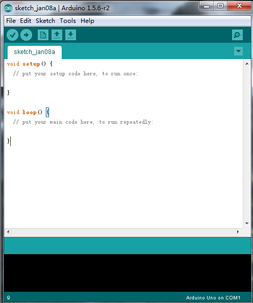
The functions of each button on the Toolbar are listed below:
![]()
The Arduino Hardware
The Arduino board is a small microcontroller board,which is a small circuit (the board) that contains a whole computer on a small chip (the microcontroller). It is a lot cheaper and very useful to build interesting devices.
The UNO is the best board to get started with electronics and coding. If this is your first experience tinkering with the platform, the UNO is the most robust board you can start playing with. The UNO is the most used and documented board of the whole Arduino family.
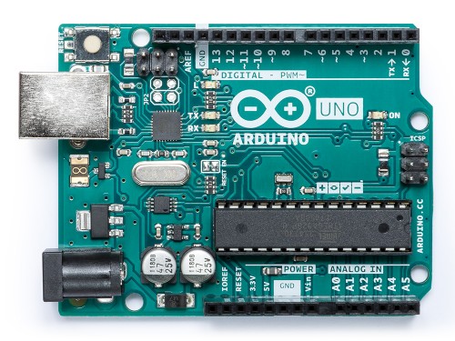
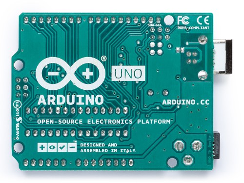
Look at the Arduino UNO REV3 Board:
At first,all those connectors might be a little confusing. Here is an explanation of what every element of the board does: https://store.arduino.cc/arduino-uno-rev3
keyestudio UNO Development Board
Let's take a look at the details of this development board with the following chart:
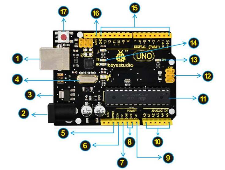
| USB Connection
Arduino board can be powered via USB connector. | |
| DC Power Jack
Arduino board can be supplied with power from the DC power jack | |
| Voltage Regulator
To control the voltage provided to the Arduino board, as well as to stabilize the DC voltage used by the processor and other components. | |
| Crystal Oscillator
Helping Arduino deal with time problems. How does Arduino calculate time? by using a crystal oscillator. The number printed on the top of the Arduino crystal is 16.000H9H. It tells us that the frequency is 16,000,000 Hertz or 16MHz. | |
| Arduino RESET
You can reset your Arduino board, for example, start the program from the very beginning. Firstly, use the RESET button(17). Or you can connect an external reset button to Arduino pin 5 labeled RESET | |
| Pin Header(3.3V,5V,GND,Vin
| |
| Analog Pins
Arduino UNO board has 6 analog inputs, labeled A0 through A5. These pins can read the signal from analog sensors (such as humidity sensor or temperature sensor), and convert it into the digital value that can read by microcontrollers) | |
| Microcontroller
Each Arduino board has its own microcontroller. You can regard it as the brain of your board. | |
| ICSP (In-Circuit Serial Programming) Header
In most case, ICSP is the AVR,an Arduino micro-header consisting of MOSI, MISO, SCK, RESET, VCC, and GND.It is often called the SPI (serial peripheral interface) and can be considered an "extension" of the output.In fact, slave the output devices under the SPI bus host. | |
| Power LED Indicator
Powering the Arduino, LED on means that your circuit board is correctly powered on. If LED is off, connection is wrong. | |
| TX and RX LED
Onboard you can find two labels: RX(receive ) and TX (transmit) | |
| Digital I/O
Arduino UNO has 14 digital input/output pins (of which 6 can be used as PWM outputs). These pins can be configured as digital input pin to read the logic value (0 or 1). Or used as digital output pin to drive different modules like LED, relay, etc. The pin labeled “〜” can be used to generate PWM. | |
| AREF
Reference voltage( 0-5V) for the analog inputs. Used with analogReference(). |
