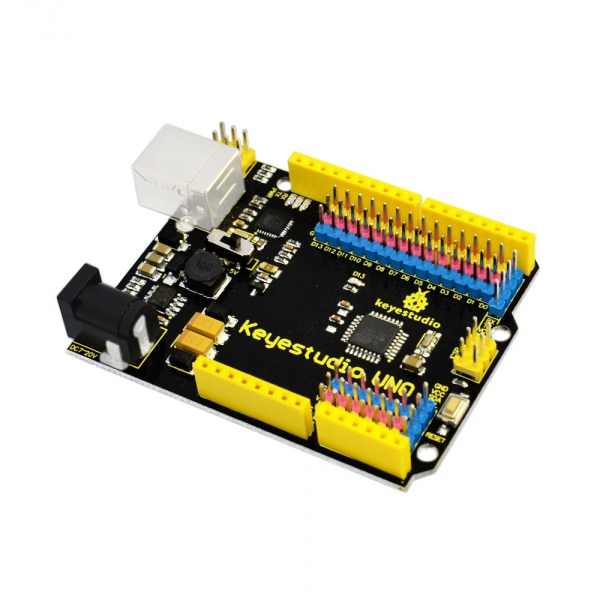
Ks0172 keyestudio UNO with Pin Header Interface: Difference between revisions
Keyestudio (talk | contribs) No edit summary |
Keyestudio (talk | contribs) |
||
| Line 2: | Line 2: | ||
==Introduction== | ==Introduction== | ||
keyestudio UNO with pin | keyestudio UNO with pin headers has the same basic functions as [http://wiki.keyestudio.com/index.php/Ks0001_keyestudio_UNO_R3_BOARD keyestudio UNO R3 BOARD]. It is a microcontroller board based on the [http://ww1.microchip.com/downloads/en/DeviceDoc/Atmel-7810-Automotive-Microcontrollers-ATmega328P_Datasheet.pdf ATMEGA328P-AU], which has the same function as ATMEGA328P(-PU), fully compatible with ARDUINO UNO REV3. <br> | ||
It has 14 digital input/output pins (of which 6 can be used as PWM outputs), 6 analog inputs, a 16 MHz crystal oscillator, a USB connection, a power jack, 2 ICSP headers, and a reset button. <br> | |||
This UNO with pin headers makes the improvement based on keyestudio UNO R3 board.<br> | |||
It breaks out all the digital and analog pins in the form of 3PIN headers (G, V, S). <br> | |||
S pins correspond to all 14 digital pins, 6 analog pins. G pins for ground. V pins for VCC. You can control the voltage of VCC via a slide switch for 5V or 3.3V. <br> | |||
When switched to 5V, level on serial communication port is 5V, voltage of pins is 5V. When switched to 3.3V, level on serial communication port is 3.3V, voltage of pins is 3.3V.<br> | |||
It also breaks out two 4PIN headers for serial communication and IIC communication. So it is more easier to connect external sensors and modules. <br> | |||
As for keyestudio UNO R3 board, its voltage-regulator chip is NSP1117. When connect external power, output 5V, drive current is 1A.<br> | |||
But for this keyestudio UNO with headers, its voltage-regulator chip is MP2307DN. When connect external power, output 5V, drive current is 2A.<br> | |||
It contains everything needed to support the microcontroller; simply connect it to a computer with a USB cable or power it with a AC-to-DC adapter or battery to get started.<br> | |||
== Tech Specs == | |||
{| class="wikitable" cellpadding="1" cellspacing="1" | |||
|- | |||
! scope="row" | Microcontroller | |||
|ATmega328P-PU | |||
|- | |||
! scope="row" | Operating Voltage | |||
| 5V | |||
|- | |||
! scope="row" | Input Voltage (recommended) | |||
| DC 7-12V | |||
|- | |||
! scope="row" | Digital I/O Pins | |||
| 14 (D0-D13) | |||
|- | |||
! scope="row" | PWM Digital I/O Pins | |||
| 6 (D3, D5, D6, D9, D10, D11) | |||
|- | |||
! scope="row" | Analog Input Pins | |||
| 6 (A0-A5) | |||
|- | |||
! scope="row" | DC Current per I/O Pin | |||
| 20 mA | |||
|- | |||
! scope="row" | DC Current for 3.3V Pin | |||
| 50 mA | |||
|- | |||
! scope="row" | Flash Memory | |||
| 32 KB (ATmega328) of which 0.5 KB used by bootloader | |||
|- | |||
! scope="row" | SRAM | |||
| 2 KB (ATmega328P-PU) | |||
|- | |||
! scope="row" | EEPROM | |||
| 1 KB (ATmega328P-PU) | |||
|- | |||
! scope="row" | Clock Speed | |||
| 16 MHz | |||
|- | |||
! scope="row" | LED_BUILTIN | |||
| D13 | |||
|- | |||
|} | |||
Revision as of 15:08, 2 August 2018
Introduction
keyestudio UNO with pin headers has the same basic functions as keyestudio UNO R3 BOARD. It is a microcontroller board based on the ATMEGA328P-AU, which has the same function as ATMEGA328P(-PU), fully compatible with ARDUINO UNO REV3.
It has 14 digital input/output pins (of which 6 can be used as PWM outputs), 6 analog inputs, a 16 MHz crystal oscillator, a USB connection, a power jack, 2 ICSP headers, and a reset button.
This UNO with pin headers makes the improvement based on keyestudio UNO R3 board.
It breaks out all the digital and analog pins in the form of 3PIN headers (G, V, S).
S pins correspond to all 14 digital pins, 6 analog pins. G pins for ground. V pins for VCC. You can control the voltage of VCC via a slide switch for 5V or 3.3V.
When switched to 5V, level on serial communication port is 5V, voltage of pins is 5V. When switched to 3.3V, level on serial communication port is 3.3V, voltage of pins is 3.3V.
It also breaks out two 4PIN headers for serial communication and IIC communication. So it is more easier to connect external sensors and modules.
As for keyestudio UNO R3 board, its voltage-regulator chip is NSP1117. When connect external power, output 5V, drive current is 1A.
But for this keyestudio UNO with headers, its voltage-regulator chip is MP2307DN. When connect external power, output 5V, drive current is 2A.
It contains everything needed to support the microcontroller; simply connect it to a computer with a USB cable or power it with a AC-to-DC adapter or battery to get started.
Tech Specs
| Microcontroller | ATmega328P-PU |
|---|---|
| Operating Voltage | 5V |
| Input Voltage (recommended) | DC 7-12V |
| Digital I/O Pins | 14 (D0-D13) |
| PWM Digital I/O Pins | 6 (D3, D5, D6, D9, D10, D11) |
| Analog Input Pins | 6 (A0-A5) |
| DC Current per I/O Pin | 20 mA |
| DC Current for 3.3V Pin | 50 mA |
| Flash Memory | 32 KB (ATmega328) of which 0.5 KB used by bootloader |
| SRAM | 2 KB (ATmega328P-PU) |
| EEPROM | 1 KB (ATmega328P-PU) |
| Clock Speed | 16 MHz |
| LED_BUILTIN | D13 |
