Ks0424 keyestudio micro:bit Passive Buzzer Module: Difference between revisions
Keyestudio (talk | contribs) No edit summary |
Keyestudio (talk | contribs) No edit summary |
||
| Line 1: | Line 1: | ||
[[image:Ks0424-1.png|thumb|300px|right|keyestudio Passive Buzzer Module For BBC micro:bit]] | |||
[[image: | |||
<br> | <br> | ||
==Description== | ==Description== | ||
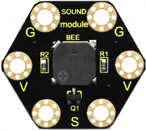
This keyestudio | This keyestudio passive buzzer is fully compatible with micro:bit control board.<br> | ||
It is mainly composed of a | It is mainly composed of a passive buzzer without oscillation circuit. It cannot be actuated by itself, but by external pulse frequencies. <br> | ||
Different frequencies produce different sounds. Even can code the melody of a song.<br> | |||
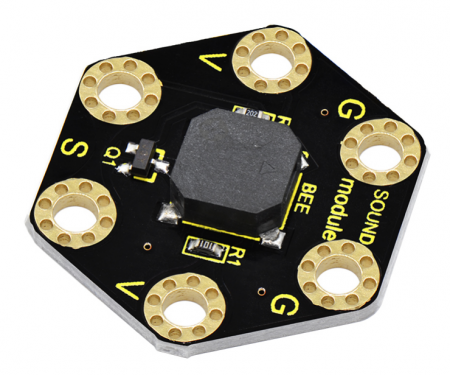
There are total 6 rings on the module. Note that two G rings, two V rings and two S rings are connected. G for ground; V for 3V; S for signal pin(0 1 2).<br> | |||
There are total 6 rings on the module. Note that two G rings, two V rings and two S rings are | |||
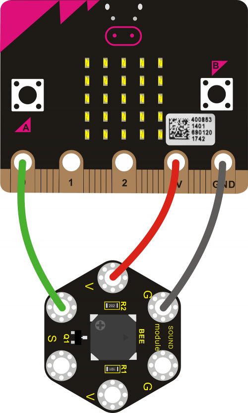
When using, connect the module to micro:bit control board using Crocodile clip line. | When using, connect the module to micro:bit control board using Crocodile clip line. | ||
<br> | <br> | ||
| Line 19: | Line 14: | ||
== Technical Parameters == | == Technical Parameters == | ||
* Working voltage: DC 3.0-3.3V | * Working voltage: DC 3.0-3.3V | ||
* Output signal: | * Output signal: Digital signal (square wave) | ||
* Dimensions: 31mm*27mm* | * Dimensions: 31mm*27mm*4.5mm | ||
* Weight: | * Weight: 2.3g | ||
* Environmental attributes: ROHS | * Environmental attributes: ROHS | ||
<br>[[File: | <br>[[File:Ks0424-2.png|450px|frameless|thumb]]<br> | ||
<br> | <br> | ||
== Connection Diagram== | == Connection Diagram== | ||
[[File: | [[File:Ks0424-3.png|500px|frameless|thumb]]<br> | ||
<br> | <br> | ||
== Source Code == | == Source Code == | ||
<br> | <br> | ||
Code 1: <br> | |||
<br>[[File:Ks0424-4.png|600px|frameless|thumb]]<br> | |||
<br> | |||
Code 2: <br> | |||
<br>[[File:Ks0424-4.png|600px|frameless|thumb]]<br> | |||
<br> | <br> | ||
<span style=color:red> Pay close attention to: you can turn the potentiometer on the module to adjust the sound magnification, which also will enlarge the analog value.<br> | <span style=color:red> Pay close attention to: you can turn the potentiometer on the module to adjust the sound magnification, which also will enlarge the analog value.<br> | ||
<br>[[File:Ks0423-5.png|600px|frameless|thumb]]<br> | |||
== Example Result == | |||
Connect well the module, then send the source code to the micro:bit main board.<br> | |||
If send the code 1, the buzzer will alternately make two sounds.<br> | |||
If send the code 2, the buzzer will play a song of Ode To Joy. | |||
<br>[[File:Ks0423-5.png|600px|frameless|thumb]]<br> | <br>[[File:Ks0423-5.png|600px|frameless|thumb]]<br> | ||
Revision as of 16:31, 4 April 2019
Description
This keyestudio passive buzzer is fully compatible with micro:bit control board.
It is mainly composed of a passive buzzer without oscillation circuit. It cannot be actuated by itself, but by external pulse frequencies.
Different frequencies produce different sounds. Even can code the melody of a song.
There are total 6 rings on the module. Note that two G rings, two V rings and two S rings are connected. G for ground; V for 3V; S for signal pin(0 1 2).
When using, connect the module to micro:bit control board using Crocodile clip line.
Technical Parameters
- Working voltage: DC 3.0-3.3V
- Output signal: Digital signal (square wave)
- Dimensions: 31mm*27mm*4.5mm
- Weight: 2.3g
- Environmental attributes: ROHS
Connection Diagram
Source Code
Pay close attention to: you can turn the potentiometer on the module to adjust the sound magnification, which also will enlarge the analog value.
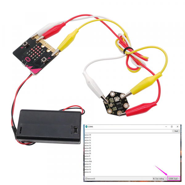
Example Result
Connect well the module, then send the source code to the micro:bit main board.
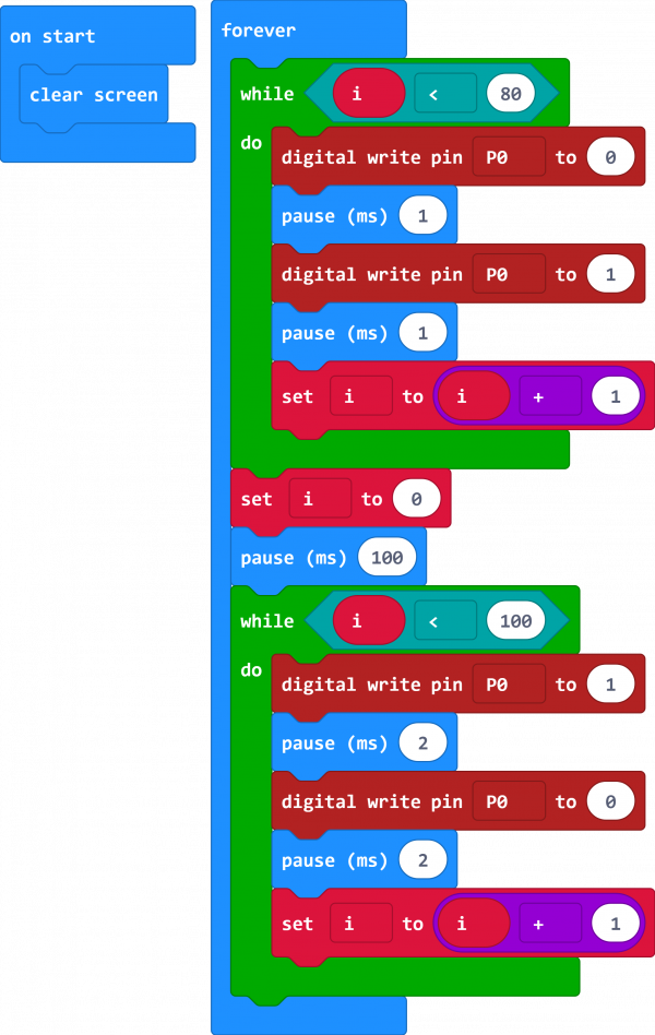
If send the code 1, the buzzer will alternately make two sounds.
If send the code 2, the buzzer will play a song of Ode To Joy.

Resources
Download all relevant info. below:
