KS0218 keyestudio RPI L298P Motor Drive Shield: Difference between revisions
Keyestudio (talk | contribs) |
Keyestudio (talk | contribs) |
||
| Line 196: | Line 196: | ||
<br> | <br> | ||
== Resources== | == Resources== | ||
*File Download: <br> | *'''File Download:''' <br> | ||
https://drive.google.com/open?id=156gDbBzONux9G6TY0dWpN2JL9JuI-c3F | https://drive.google.com/open?id=156gDbBzONux9G6TY0dWpN2JL9JuI-c3F | ||
*'''Source Code:''' <br> | |||
https://drive.google.com/open?id=1WaZAPNvdbKUaCJVU62EwL793C1RcyNkL | |||
<br> | <br> | ||
== Get One Now == | == Get One Now == | ||
*[https://www.keyestudio.com/keyestudio-rpi-l298p-motor-drive-shield-for-arduino-raspberry-pi-p0343.html '''Official website''' ] | *[https://www.keyestudio.com/keyestudio-rpi-l298p-motor-drive-shield-for-arduino-raspberry-pi-p0343.html '''Official website''' ] | ||
Revision as of 10:40, 19 April 2019
Introduction
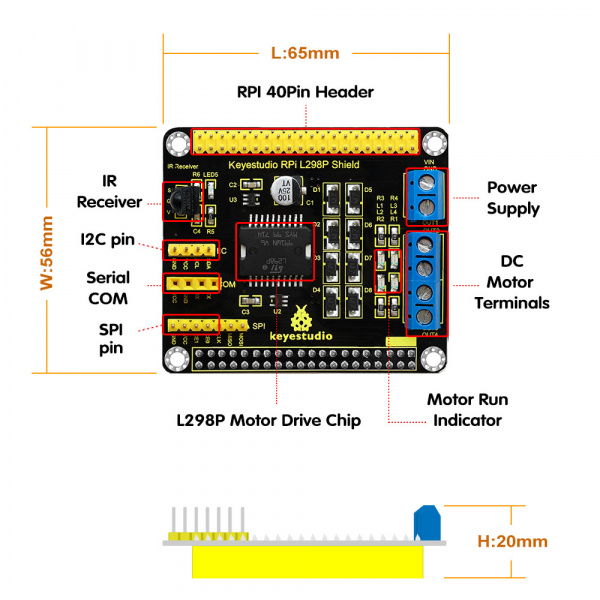
Keyestudio RPI L298P motor drive shield adopts high-power motor driver chip L298P, which can directly drive two DC motors, with drive current up to 2A, and motor output terminal uses eight high-speed Schottky diodes as protection.
The shield is fully compatible with various versions of Raspberry Pi. Meanwhile, the shield has leaded out each interface for simple connection of other sensors. This shield also has an IR receiver, so you can use infrared remote control to communicate with it.
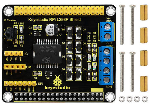
To make it easier for you to mount the shield to your Raspberry Pi, we have specially provided you with 4 M2.5*20MM round-head screws, 4 double-pass M2.5*10MM copper pillars and 4 M2.5 nickel-plating Nuts.
Specification
- Logic part input voltage: 5V
- Driving part input voltage: 4.8 ~ 24V
- Logic part working current Iss: ≤36mA
- Driving part working current Io: ≤ 2A
- Maximum power dissipation: 25W (T=75℃)
- Control signal input level:
 High level: 2.3V ≤ Vin ≤ 5V
 Low level: 0V ≤ Vin ≤ 1.5V
- Working temperature: -25℃~+130℃
- Driver form: Dual power H bridge driving
Connection Diagram
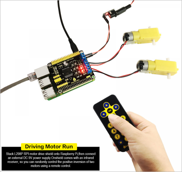
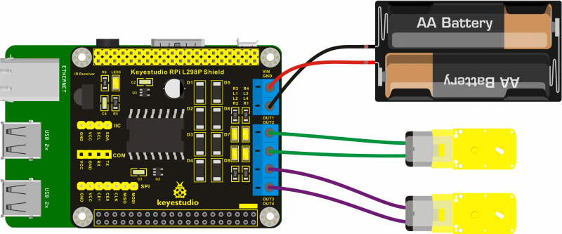
Connect the motors and batteries to the terminal block of RPI L298P shield.
Sample Code
#include <wiringPi.h>
#include <stdio.h>
#include <string.h>
#include <errno.h>
#include <wiringSerial.h>
#define PIN 27
#define IO digitalRead(PIN)
unsigned char i,idx,cnt;
unsigned char count;
unsigned char data[4];
char a;
long  up  = 0x40;
long  back = 0x15;
long  stop = 0x46;
long  left = 0x44;
long  right= 0x43;
long  esc= 0x4a;


int main()
{
    wiringPiSetup();
    pinMode(PIN, INPUT);
    pullUpDnControl(PIN, PUD_UP);
    pinMode(1,OUTPUT);
    int fd ;

    pinMode(22,OUTPUT);
    pinMode(26,OUTPUT);
    pinMode(21,OUTPUT);
    pinMode(30,OUTPUT);
    printf("L298P test......\n");
    for(a=0;a<2;a++)
       {
       digitalWrite(21,HIGH);
       digitalWrite(26,HIGH);
       digitalWrite(22,LOW);
       digitalWrite(30,LOW);
       delay(1000);
       digitalWrite(22,HIGH);
       digitalWrite(30,HIGH);
       delay(1000);
       digitalWrite(21,LOW);
       digitalWrite(26,LOW);
       delay(1000);
       digitalWrite(22,LOW);
       digitalWrite(30,LOW);
       delay(1000);
       }
       printf("IRM Test Program ... \n");

	while (data[2]  != esc )
	{
		if(IO == 0)
		{
			count = 0;
			while(IO == 0 && count++ < 200)   //9ms
		    	delayMicroseconds(60);

			count = 0;
			while(IO == 1 && count++ < 80)	  //4.5ms
		    	delayMicroseconds(60);

			idx = 0;
			cnt = 0;
			data[0]=0;
			data[1]=0;
			data[2]=0;
			data[3]=0;
			for(i =0;i<32;i++)
			{
				count = 0;
				while(IO == 0 && count++ < 15)  //0.56ms
		    		delayMicroseconds(60);

				count = 0;
				while(IO == 1 && count++ < 40)  //0: 0.56ms; 1: 1.69ms
		    		delayMicroseconds(60);

				if (count > 25)data[idx] |= (1<<cnt);
				if(cnt == 7)
				{
					cnt = 0;
					idx++;
				}
				else cnt++;
			}

			if(data[0]+data[1] == 0xFF && data[2]+data[3]==0xFF)	//check
				printf("Get the key: 0x%02x\n",data[2]);
                 if (data[2]  == up )
			    {
                      digitalWrite(21,HIGH);
                      digitalWrite(26,HIGH);
                      digitalWrite(22,LOW);
                      digitalWrite(30,LOW);
                      delay(1000);
				}
                  if (data[2]  == back )
				{
                      digitalWrite(21,LOW);
                      digitalWrite(26,LOW);
                      digitalWrite(22,HIGH);
                      digitalWrite(30,HIGH);
                      delay(1000);
				}
                   if (data[2]  == stop )
				{
                      digitalWrite(21,HIGH);
                      digitalWrite(26,HIGH);
                      digitalWrite(22,HIGH);
                      digitalWrite(30,HIGH);
                      delay(1000);
				}
                     if (data[2]  == left )
				{
                      digitalWrite(21,HIGH);
                      digitalWrite(26,LOW);
                      digitalWrite(22,LOW);
                      digitalWrite(30,HIGH);
                      delay(1000);
				}
                     if (data[2]  == right )
				{
                      digitalWrite(21,LOW);
                      digitalWrite(26,HIGH);
                      digitalWrite(22,HIGH);
                      digitalWrite(30,LOW);
                      delay(1000);
				}
		}
	}
 printf("Bluetooth Test Program ... \n");
 if ((fd = serialOpen ("/dev/ttyAMA0", 9600)) < 0)
  {
    fprintf (stderr, "Unable to open serial device: %s\n", strerror (errno)) ;
    return 1 ;
  }

// Loop, getting and printing characters
  while(1)
 {
    putchar (serialGetchar (fd)) ;
    fflush (stdout) ;
   }
}
Using Method
A. Use the WinSCP to place rpi_L298P folder into the Raspberry system. Shown as below.
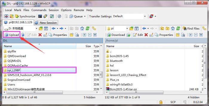
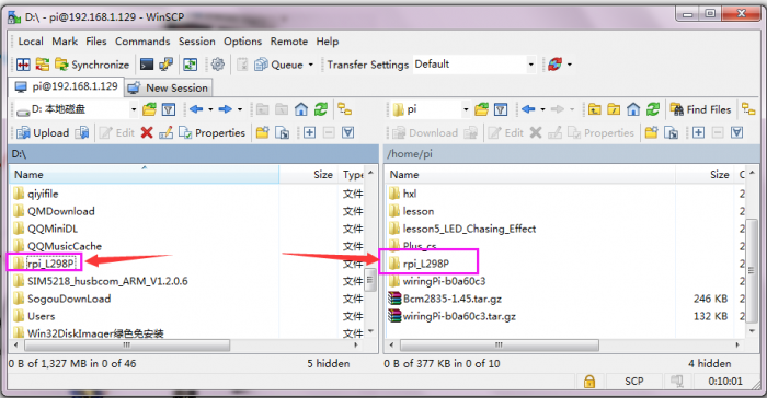
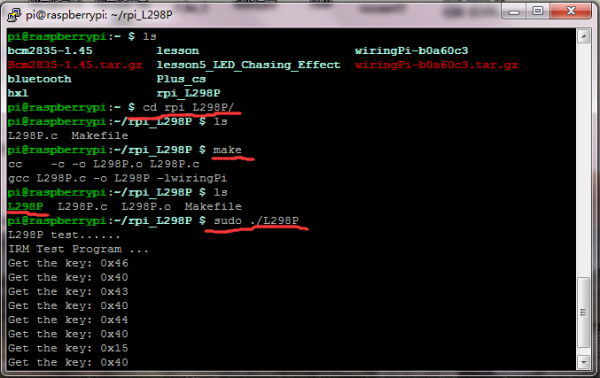
B. On the terminal input cd rpi_L298P to enter the folder.
C. On the terminal execute make, it will generate a L298P executable file inside the folder.
D. Wire it up as the above diagram, then enter rpi_L298P folder, on the terminal execute the sudo ./L298P, firstly test two motors, and two DC motors will turn forward for one second, reverse for one second, then stop for one second, loop twice. Then, aimed at the infrared receiver, press down the button on the infrared remote control, you will see the Raspberry Pi terminal display the corresponding data.
When press down the up, down, left, right and OK key of remote control, the shield will control the two motors run, to simulate the car go forward, backward, turn left, turn right and stop.
E. Ctrl + C can exit the processing.
Resources
- File Download:
https://drive.google.com/open?id=156gDbBzONux9G6TY0dWpN2JL9JuI-c3F
- Source Code:
https://drive.google.com/open?id=1WaZAPNvdbKUaCJVU62EwL793C1RcyNkL
