Ks0192 keyestudio 4WD Bluetooth Multi-functional Car: Difference between revisions
Keyestudio (talk | contribs) |
Keyestudio (talk | contribs) |
||
| Line 199: | Line 199: | ||
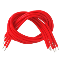
| align="center" | Connector Wire (150mm, Red) | | align="center" | Connector Wire (150mm, Red) | ||
| align="center" | 6 | | align="center" | 6 | ||
| align="center" | <br>[[File:19230.png| | | align="center" | <br>[[File:19230.png|200px|frameless|thumb]]<br> | ||
|- | |- | ||
Revision as of 09:39, 24 September 2016
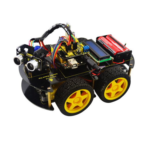
keyestudio 4WD Bluetooth Multi-functional Car
Introduction
keyestudio 4WD Bluetooth Multi-functional Car is a learning application development system based on microcontroller and with ATmega-328 as core. It has functions of line tracking, obstacle avoidance, IR remote control , Bluetooth remote control and detecting distance. This kit contains plenty of interesting programs and can extend an external circuit module to increase more functions of this car. The kit aims to disengage users from boring theories and obtain capacity of system development when they are learning Arduino.
Parameters
1.Motor: Voltage: 6-9V Reduction Ratio: 1:48
2.Choosing L298N driver module as control motor, separated from microcontrollor
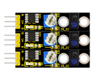
3.Three line tracking modules, having higher precision when detecting white and black lines,able to realize anti-falling
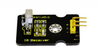
4.IR remote control module making up a remote control system of the car
5.Using ultrasonic module to realize obstacle avoidance
6.Pairing mobile phone Bluetooth with Bluetooth remote control module to control the car
7.Able to connect with external voltage at 7~12V,and equip with various sensors to complete different functions as much as possible
Component List
Project List
Project 1:Line Tracking Sensor
Project 2:Ultrasonic Sensor
Project 3: Digital IR Receiver Module
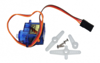
Project 4: Servo Motor
Project 5: Bluetooth Module
Project 6: L298N Motor Driver
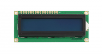
Project 7: I2C 1602 LCD
Project 8:Line Tracking of Smart Car
Project 9:Obstacle Avoidance of Smart Car
Project 10:IR Remote Control of Smart Car
Project 11:Distance Detecting of Smart Car
Project 12:Bluetooth Remote Control of Smart Car
Project 13:5 in 1 Muilti-functional Car
Address of Assembly Video
http://www.keyestudio.com/wp/2016/09/ks0192
Address of Demonstration Video
Project Details
Project 1:Line Tracking Sensor
Introduction:
This Line Tracking Sensor can detect white lines in black and black lines in white. The single line-tracking signal provides a stable output signal TTL for a more accurate and more stable line. Multi-channel option can be easily achieved by installing required line-tracking robot sensors.
Specification:
Power Supply: +5V
Operating Current: <10mA
Operating Temperature Range: 0°C ~ + 50°C
Output Interface: 3-wire interface (1 - signal, 2 - power, 3 - power supply negative)
Output Level: TTL level
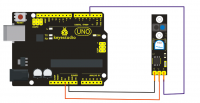
Connection Diagram:
Sample Code:
const int sensorPin = 3;     // the number of the sensor pin
const int ledPin =  13;      // the number of the LED pin
int sensorState = 0;         // variable for reading the sensor status
void setup() {
  pinMode(ledPin, OUTPUT);
  pinMode(sensorPin, INPUT); }
void loop(){
  // read the state of the sensor value:
  sensorState = digitalRead(sensorPin);
  // if the sensorState is HIGH:
  if (sensorState == HIGH) {
     digitalWrite(ledPin, HIGH);
  }
  else {digitalWrite(ledPin, LOW);
  }}
