Ks0193 keyestudio Self-balancing Car: Difference between revisions
Keyestudio (talk | contribs) |
Keyestudio (talk | contribs) |
||
| Line 221: | Line 221: | ||
Screw each copper hex couplers with two screws. Then fix the two copper couplers on the two motors using a wrench. | Screw each copper hex couplers with two screws. Then fix the two copper couplers on the two motors using a wrench. | ||
<br>[[File:KS0193-图片33.png|500px|frameless|thumb]]<br> | <br>[[File:KS0193-图片33.png|500px|frameless|thumb]]<br> | ||
<br>[[File:|500px|frameless|thumb]]<br> | <br>[[File:KS0193-图片34.png|500px|frameless|thumb]]<br> | ||
Finally mount the two wheels to the two hex copper couplers using 2pcs M4*6MM black screws. | Finally mount the two wheels to the two hex copper couplers using 2pcs M4*6MM black screws. | ||
<br>[[File:KS0193-图片35.png|500px|frameless|thumb]]<br> | <br>[[File:KS0193-图片35.png|500px|frameless|thumb]]<br> | ||
Revision as of 15:25, 25 April 2019
Overview
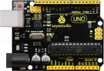
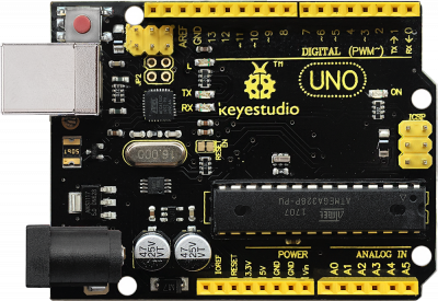
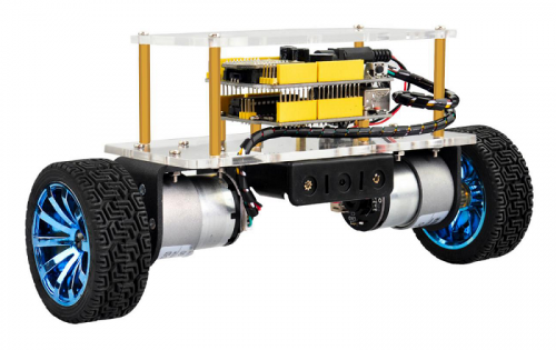
How to DIY a mini balance car on your own? This balance car kit is based on Arduino development platform. We mainly use UNO R3 as core and balance shield with built-in MPU-6050 as drive board to test the car body posture.
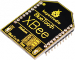
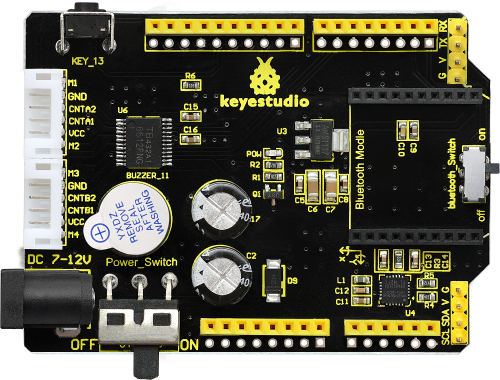
The balance shield comes with a Bluetooth interface, fully compatible with the Bluetooth XBee module (only compatible with Andriod system).
When connecting to Bluetooth, you can easily control the moving direction of balance car with Bluetooth APP, making a variety of unique postures.
To facilitate the operation control, Bluetooth APP has both key and gravity control modes.
Moreover, it adds the function of adjusting the balance angle and PID parameters as well, so you can perfectly adjust and control the balance car.
No need to worry how to play it. We can provide you with all assembly components, as well as the corresponding installation, debugging method and program.
Operation Principle
The self-balancing car uses the power of the car body to maintain the relative balance, which is a process of dynamic balance.
The power to maintain the balance of the car comes from the movement of the wheels, driven by two DC motors.
The control of the car body can be divided into three control tasks as follows:
- 1. Balance Control: keep the car upright and balanced by controlling the forward and backward rotation of the car’s wheel.
- 2. Speed Control: realize the front and rear movement and speed control by controlling the inclination of the car. In fact, it is achieved finally by controlling the speed of the motor.
- 3. Direction Control: realize the steering control by controlling the rotational speed differences between the two motors of the car.
In this way, it is relatively simple to understand the three control tasks.
But in the final control process, it comes down to the control of a control quantity. So there will be coupling between the three tasks, which will interfere with each other.
The key is to control the car’s balance; the speed and direction control should be as smooth as possible.
Parameters of balance car
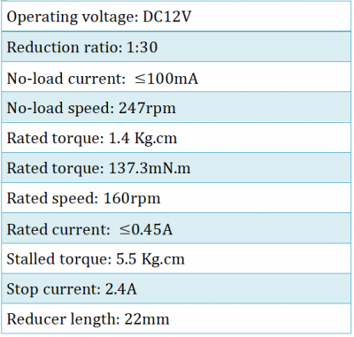
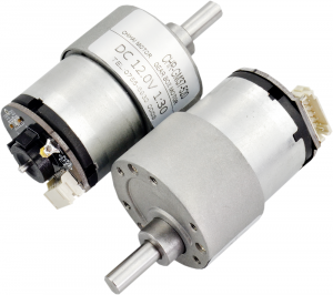
- 1.Motor parameters:
- 2.Working voltage: DC 9-12V
- 3.Motor drive chip: TB6612FNG
- 4.Body posture detection: MPU-6050
- 5.Comes with power control switch
- 6.Comes with Bluetooth control switch for controlling serial communication
Pay special attention to:
The balance shield comes with a slide switch for controlling the Bluetooth communication.
When upload the source code, must turn the slide switch OFF; otherwise, code uploading will fail.
When connecting to the Bluetooth module, should turn the slide switch ON.
Kit List
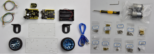
The kit packaging contains all electronic components for this self-balancing car. As you work your way through each project, you will learn how to control the car.
Assembly Steps
(1) Prepare all the components shown below.
(2) To begin with, we start to install the bottom Acrylic plate.
Find out the parts below:
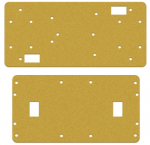
- Bottom Acrylic plate
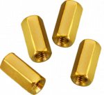
- Dual-pass M3*10MM hex copper pillar x 4pcs
- M3*8MM screw x 4pcs
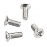
- M3*12MM flat head screw x 2pcs
- M3 nickel plating nut x 2pcs
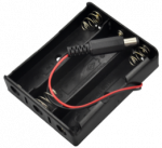
- Battery case
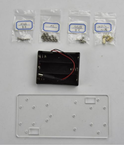
We are now going to mount the battery case and copper pillars on the Acrylic plate.
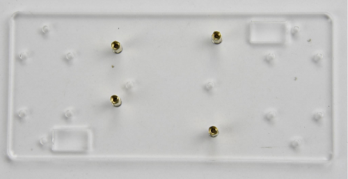
Fix the 4pcs M3*10MM copper pillar onto the Acrylic plate using 4pcs M3*8MM screws.
Then Mount the battery case on the Acrylic plate using 2pcs M3*12MM flat head screws and 2pcs M3 nickel plating Nuts.

(3) Next, move on to install the motor and wheel onto bottom Acrylic plate.
Find out the parts below:
- Bottom Acrylic plate mounted with battery case
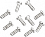
- M3*12MM round-head screw x 8pcs
- M3 nickel plating nut x 8pcs
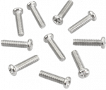
- M4*6MM black screw x 2pcs
- Two wheels
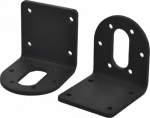
- Two black connectors
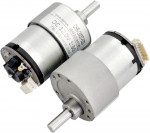
- Two motors
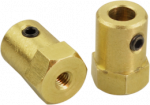
- Two copper hex couplers
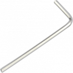
- M2 wrench Type L
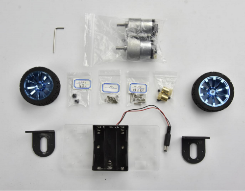
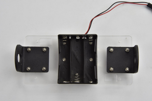
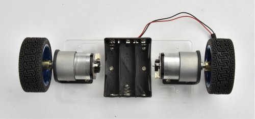
Go to mount the two black connectors onto the Acrylic plate using 8pcs M3*12MM round-head screws and 8pcs M3 nickel plating nuts. Shown below.
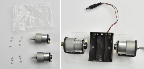
Each motor is equipped with six screws in the bag. Go to mount the two motors on the black connectors using the screws.
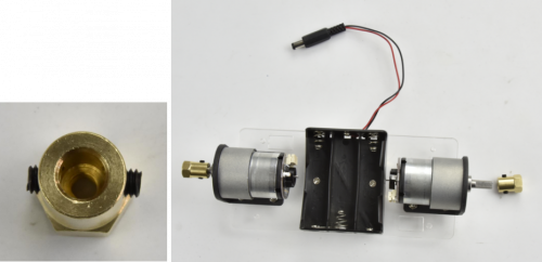
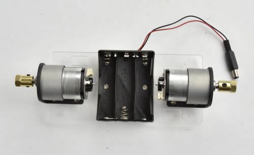
Screw each copper hex couplers with two screws. Then fix the two copper couplers on the two motors using a wrench.
Finally mount the two wheels to the two hex copper couplers using 2pcs M4*6MM black screws.
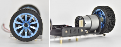
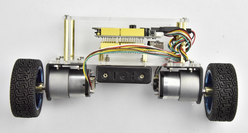
Up to now, the bottom motor wheel are installed well!
(4) The final step is to install the control board and the top Acrylic plate.
- Top Acrylic plate
- UNO R3 control board
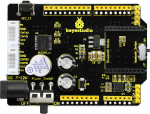
- keyestudio balance shield
- Bluetooth XBee module HC-06
- M3*6MM round-head screw x 3pcs
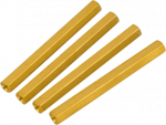
- M3*45MM copper pillar x 4pcs
- M3*8MM round-head screw x 8pcs
- 6pin 30CM connector wire x 2pcs
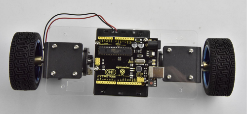
Go to screw the UNO R3 control board onto the 4pcs M3*10MM copper pillars mounted on the Acrylic plate with 3pcs M3*6MM round-head screws.
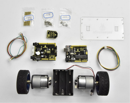
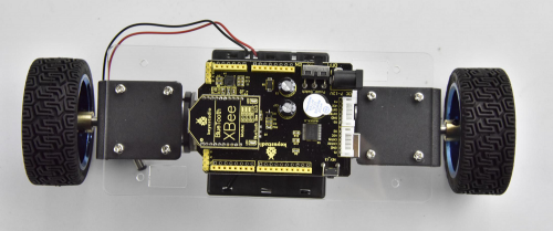
Then stack the keyestudio balance shield onto UNO R3 control board. And plug the Bluetooth XBee module HC-06 into the balance shield.
Go to connect the motor to the balance shield using 6pin PH2.0 30CM connector wire. Simply connect the motor to the nearest motor connector.
After that, screw the 4pcs M3*45MM copper pillars on the Acrylic plate with 4pcs M3*8MM round head screws. And connect well the battery plug to DC black jack of UNO R3.
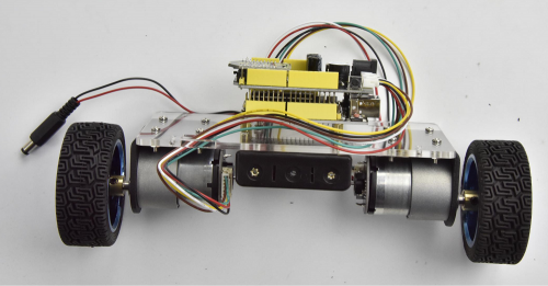
The back view is showed below:
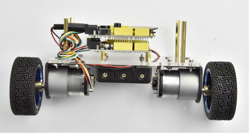
The final part is to install the top Acrylic plate onto the 4pcs M3*45MM copper pillars with 4pcs M3*8MM round-head screws.
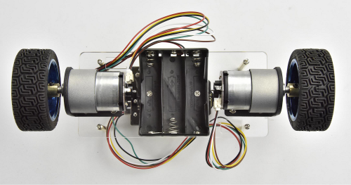
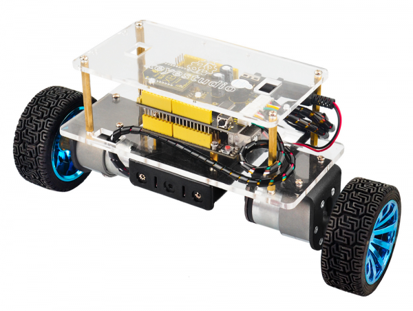
Congrats! The balance car is installed well.
