Ks0070 keyestudio UNO R3 Breadboard Kit for Arduino: Difference between revisions
Keyestudio (talk | contribs) |
Keyestudio (talk | contribs) |
||
| Line 8: | Line 8: | ||
==2. Kit Contents== | ==2. Kit Contents== | ||
1.keyestudio UNO R3 Controller | 1.keyestudio UNO R3 Controller<br> | ||
2.Wires | 2.Wires<br> | ||
3.M3*10 Copper Pillar | 3.M3*10 Copper Pillar<br> | ||
4.M3*6MM Flat Head | 4.M3*6MM Flat Head<br> | ||
5.M3*6MM Round Head | 5.M3*6MM Round Head<br> | ||
6.Yellow Button Cap | 6.Yellow Button Cap<br> | ||
7.Breadboard | 7.Breadboard<br> | ||
8.Chassis | 8.Chassis<br> | ||
9. 1-digit SDsp | 9. 1-digit SDsp<br> | ||
10.Active Buzzer | 10.Active Buzzer<br> | ||
11.Passive Buzzer | 11.Passive Buzzer<br> | ||
12.Thermistor | 12.Thermistor<br> | ||
13.10K Resistor | 13.10K Resistor<br> | ||
14.1K Resistor | 14.1K Resistor<br> | ||
15.220R Resistor | 15.220R Resistor<br> | ||
16.Tilt Switch | 16.Tilt Switch<br> | ||
17.Photoresistor | 17.Photoresistor<br> | ||
18.Flame Sensor | 18.Flame Sensor<br> | ||
19.DHT11 Sensor | 19.DHT11 Sensor<br> | ||
20.LM35DZ Sensor | 20.LM35DZ Sensor<br> | ||
21.Touch Switch | 21.Touch Switch<br> | ||
22.RGB LED | 22.RGB LED<br> | ||
23.Blue LED | 23.Blue LED<br> | ||
24.Yellow LED | 24.Yellow LED<br> | ||
25.Red LED | 25.Red LED <br> | ||
26.Potentiometer | 26.Potentiometer<br> | ||
27.Usb Cable | 27.Usb Cable<br> | ||
==3. Introduction of keyestudio UNO R3 == | ==3. Introduction of keyestudio UNO R3 == | ||
Revision as of 13:52, 9 November 2016
UNO R3 Breadboard kit for Arduino
1. Introduction
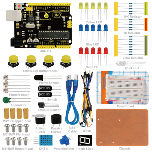
UNO R3 Breadboard kit is a learning kit based on UNO R3 development board. It's equipped with basic elements for ARDUINO experiments, including breadboard, Dupont wires, LEDs, resistors. With this kit, you can perform simple LED experiments, such as LED blinking, LED chasing effect, etc. It is both affordable and portable for your Arduino learning.
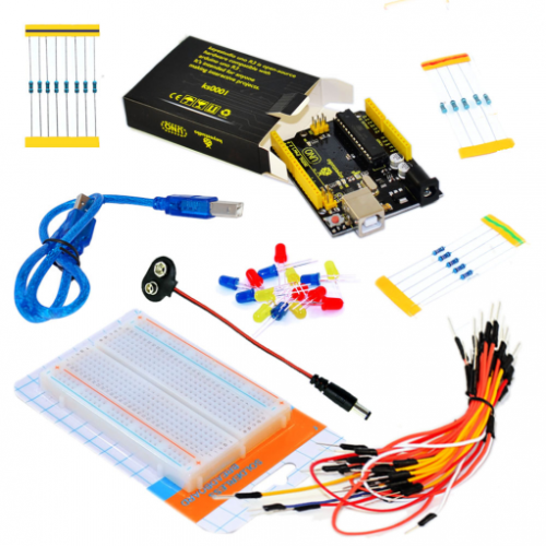
2. Kit Contents
1.keyestudio UNO R3 Controller
2.Wires
3.M3*10 Copper Pillar
4.M3*6MM Flat Head
5.M3*6MM Round Head
6.Yellow Button Cap
7.Breadboard
8.Chassis
9. 1-digit SDsp
10.Active Buzzer
11.Passive Buzzer
12.Thermistor
13.10K Resistor
14.1K Resistor
15.220R Resistor
16.Tilt Switch
17.Photoresistor
18.Flame Sensor
19.DHT11 Sensor
20.LM35DZ Sensor
21.Touch Switch
22.RGB LED
23.Blue LED
24.Yellow LED
25.Red LED
26.Potentiometer
27.Usb Cable
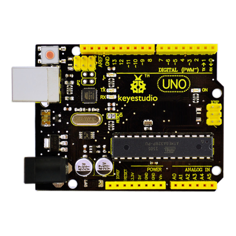
3. Introduction of keyestudio UNO R3
- Microcontroller: ATmega328
- Operating Voltage: 5V
- Input Voltage (recommended) : 7-12V
- Input Voltage (limits): 6-20V
- Digital I/O Pins: 14 (of which 6 provide PWM output)
- Analog Input Pins: 6
- DC Current per I/O Pin: 20 mA
- DC Current for 3.3V Pin: 50 mA
- Flash Memory: 32 KB (ATmega328) of which 0.5 KB used by bootloader
- SRAM: 2 KB (ATmega328)
- EEPROM: 1 KB (ATmega328)
- Clock Speed: 16 MHz
- Length: 8.6 mm
- Width: 53.4 mm
- Weight: 25 g
See http://arduino.cc for detailed specifications, overviews, schematics, etc. Core functions, code examples, and links to many of the device libraries can be found in the learning section; refer to the manufacturer's site if using other add-on shields or sensors.
The latest Arduino Integrated Development Environment (IDE) necessary for programming your UNO R3 board can be obtained at http://arduino.cc/en/Main/Software (the Download menu choice on Arduino.cc)
Examples for many basic components can be found under the Examples menu. As you install libraries for additional shields, new examples may be available.
Follow the getting started guide found on the arduino.cc web site. Click Learning, and select Getting started. Click on the link for Windows, Mac OS X, or Linux for more specific directions.
4. Getting Started
1. Download the Arduino Environment (IDE) and install or unzip/extract the application directory.
2. Connect the UNO board to one of your computer's USB port.
3. Install the drivers (If the computer does not automatically download and install the necessary USB drivers, point the hardware setup to the "drivers" directory of the Arduino IDE application.)
4. Launch the Arduino IDE application
5. Open a sketch example such as "Blink"
6. Select your Board from the Tools menu.
7. Select the Serial Port used by the board
8. Upload the sketch to the board
5. Project Details
Project 1: LED Blinking
Introduction:
Blinking LED experiment is quite simple. In the "Hello World!" program, we have come across LED. This time, we are going to connect an LED to one of the digital pins rather than using LED13, which is soldered to the board. Except an Arduino and an USB cable, we will need extra parts as below.
Hardware Required:
1. Unor3 Board *1
2. Red M5 LED*1
3. 220Ω Resistor*1
4. Breadboard*1
5. Breadboard Jumper Wires* several
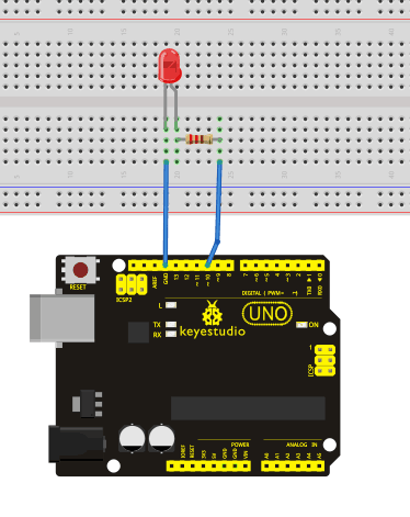
We follow below diagram from the experimental schematic link. Here we use digital pin 10. We connect LED to a 220 ohm resistor to avoid high current damaging the LED.
Connection Diagram:
Sample Code:
According to the above circuit, you can start compiling the program, turning the LED 1 second on and 1 second off. This program is simple and similar to one that comes with Arduino except it’s connected to digital pin 10.
int ledPin = 10; // define digital pin 10.
void setup()
{
pinMode(ledPin, OUTPUT);// define pin with LED connected as output.
}
void loop()
{
digitalWrite(ledPin, HIGH); // set the LED on.
delay(1000); // wait for a second.
digitalWrite(ledPin, LOW); // set the LED off.
delay(1000); // wait for a second
}
}
Result:
After downloading this program, in the experiment, you will see the LED connected to pin 10 turning on and off, with an interval approximately one second.
The blinking LED experiment is now completed.
Project 2:Traffic Light
Introduction:
In the previous program, we have done the LED blinking experiment with one LED. Now, it’s time to up the stakes and do a bit more complicated experiment-traffic lights. Actually, these two experiments are similar. While in this traffic lights experiment, we use 3 LEDs with different color other than 1 LED.
Hardware Required:
1. Unor3 board *1
2. USB cable *1
3. Red M5 LED*1
4. Yellow M5 LED*1
5. Green M5 LED*1
6. 220Ω resistor *3
7. Breadboard*1
8. Breadboard jumper wires* several
Connection Diagram:
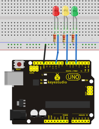
With the above parts ready, we can get started. We can refer to the LED blinking experiment for this one. Below is a sample schematic diagram. Pins we use are digital pin 10, 7 and 4.
Sample Code:
Since it is a simulation of traffic lights, the blinking time of each LED should be the same with those in traffic lights system. In this program, we use Arduino delay () function to control delay time, which is much simpler than C language.
int redled =10; // initialize digital pin 8.
int yellowled =7; // initialize digital pin 7.
int greenled =4; // initialize digital pin 4.
void setup()
{
pinMode(redled, OUTPUT);// set the pin with red LED as “output”
pinMode(yellowled, OUTPUT); // set the pin with yellow LED as “output”
pinMode(greenled, OUTPUT); // set the pin with green LED as “output”
}
void loop()
{
digitalWrite(greenled, HIGH);//// turn on green LED

delay(5000);// wait 5 seconds
digitalWrite(greenled, LOW); // turn off green LED
for(int i=0;i<3;i++)// blinks for 3 times
{
delay(500);// wait 0.5 second
digitalWrite(yellowled, HIGH);// turn on yellow LED
delay(500);// wait 0.5 second
digitalWrite(yellowled, LOW);// turn off yellow LED
}
delay(500);// wait 0.5 second
digitalWrite(redled, HIGH);// turn on red LED
delay(5000);// wait 5 second
digitalWrite(redled, LOW);// turn off red LED
}
Result:
When the uploading process is completed, we can see traffic lights of our own design.
Note: this circuit design is very similar with the one in LED chase effect. The green light will be on for 5 seconds, and then off., followed by the yellow light blinking for 3 times, and then the red light on for 5 seconds, forming a cycle. Cycle then repeats. Experiment is now completed, thank you.
Project 3: LED Chasing Effect
Introduction:
We often see billboards composed of colorful LEDs. They are constantly changing to form various patterns. In this experiment, we compile a program to simulate chase effect.
Hardware Required:
1. Led x6
2. 220Ω Resistor x6
3. Colorful Breadboard Wires
Connection Diagram:
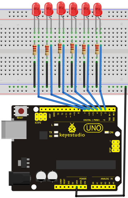
According to the wiring method of diodes, six LEDs are connected to digital 2~7 pins. As shown in fig.: LED chase effect wiring circuit:
Sample Code:
int BASE = 2 ;  // the I/O pin for the first LED
int NUM = 8;   // number of LEDs

void setup()
{
   for (int i = BASE; i < BASE + NUM; i ++)
   {
     pinMode(i, OUTPUT);   // set I/O pins as output
   }

}

void loop()
{
   for (int i = BASE; i < BASE + NUM; i ++)
   {
     digitalWrite(i, LOW);    // set I/O pins as “low”, turn off LEDs one by one.
     delay(200);        // delay
   }
   for (int i = BASE; i < BASE + NUM; i ++)
   {
     digitalWrite(i, HIGH);    // set I/O pins as “high”, turn on LEDs one by one
     delay(200);        // delay
   }
}
Result:
You can see the LEDs blink by sequence.
Video
http://www.keyestudio.com/wp/2016/05/ks0070-uno-r3-breadboard-kit-for-arduino/
