KS0085 Keyestudio Smart Home Kit for Arduino: Difference between revisions
Keyestudio (talk | contribs) No edit summary |
Keyestudio (talk | contribs) No edit summary |
||
| Line 18: | Line 18: | ||
<br>[[File:Ks00856.png|frameless|thumb]]<br> | <br>[[File:Ks00856.png|frameless|thumb]]<br> | ||
== Keyestudio PLUS Control Board == | |||
'''Description''' | '''Description''' | ||
| Line 53: | Line 54: | ||
<br>[[File:Arduino1.5.6- setup 5.png|800px|frameless|thumb]]<br> | <br>[[File:Arduino1.5.6- setup 5.png|800px|frameless|thumb]]<br> | ||
=== | |||
'''Installing Driver''' | '''Installing Driver''' === | ||
Finish the download, now, let’s install the driver of keyestudio PLUS control board. Its chip is CP2102 serial chip. | Finish the download, now, let’s install the driver of keyestudio PLUS control board. Its chip is CP2102 serial chip. | ||
| Line 63: | Line 64: | ||
<br>[[File:Arduino1.5.6- setup 5.png|800px|frameless|thumb]]<br> | <br>[[File:Arduino1.5.6- setup 5.png|800px|frameless|thumb]]<br> | ||
Double click [[File:Arduino1.5.6- setup 5.png|800px|frameless|thumb]], click to next step,as shown below: | Double click [[File:Arduino1.5.6- setup 5.png|800px|frameless|thumb]], click to next step,as shown below:<br> | ||
=== '''Arduino IDE Setting''' === | |||
== Keyestudio Sensor Shield V5.2 == | |||
'''Description''' | |||
In the experiments, you might often use ARDUINO control board and several sensor modules. If the interfaces of power output is not enough, you may need to add a breadboard and use many connection wires. Is it really troublesome?<br> | |||
But now, with this keyestudio sensor shield, you can easily solve that problem. This shield is fully compatible with keyestudio PLUS Control Board, so you can easily stack it onto PLUS Control Board.<br> | |||
This keyestudio sensor shield has extended the digital and analog ports out as 3PIN interface (G,V, S), which can directly connect 3PIN sensor modules.<br> | |||
It also breaks out some communication pins of 2.54mm pitch, like serial, IIC, and SPI communication.<br> | |||
The shield comes with a reset button and 2 signal indicators as well.<br> | |||
Additionally, you can supply the voltage needed to the sensor modules through blue terminal blocks on the shield. Because some sensor modules is not used with 5V or 3.3V but with special voltage.<br> | |||
'''Parameter:''' | |||
* Extends an Arduino Reset button | |||
* Comes with 1 electrolytic capacitor and 1 ceramic capacitor | |||
* Comes with a built-in power indicator and a D13 indicator | |||
* Breakout all the digital and analog ports of keyestudio PLUS Control Board as 3PIN headers | |||
* A serial communication interface | |||
* A I2C communication interface | |||
* A SPI communication interface | |||
* Comes with a URF interface | |||
* Comes with an APC220 interface | |||
* You can supply the voltage needed for sensor modules via terminal blocks | |||
'''Pins Description:''' | |||
<br>[[File:Arduino1.5.6- setup 5.png|800px|frameless|thumb]]<br> | |||
When SE is connected with jumper cap, and input DC 7V to VCC /GND terminal block, so the voltage of V, V1 and + pins are 7V. | |||
When SE is connected with jumper cap, and VCC /GND terminal block without voltage input, shield is powered via UNO R3, so the voltage of V, V1 and + pins are 5V. | |||
When SE is disconnected, input DC 7V to VCC /GND terminal block, so the voltage of V pin is 7V, the voltage of V1 and + pins are 0V. | |||
When SE is disconnected, and VCC /GND terminal block without voltage input, shield is powered via UNO R3, so the voltage of V pin is 0V, the voltage of V1 and + pins are 5V. | |||
'''Example Use''' | |||
Stack the Keyestudio Sensor Shield V5 on the Keyestudio PLUS Control Board, and build the circuit on the shield, as shown below. | |||
<br>[[File:Arduino1.5.6- setup 5.png|800px|frameless|thumb]]<br> | |||
'''Projects''' | |||
When you get this kit, there are 14 sensors/modules inside like keyestudio PLUS control board, sensor shield and dupont Lines.<br> | |||
We firstly stack Keyestudio Sensor Shield V5.2 on the keyestudio PLUS control board and connect 14 sensors to sensor shield via dupont lines, upload the test code and check the result.<br> | |||
Note: In this course, the interface of each sensor / module marked with (G,-, GND) indicates the negative pole, and G and GND are connected to Arduino board or the sensor shield; V, +, and VCC stands for positive pole, they are linked with V, VCC and 5V of Arduino board or sensor shield.<br> | |||
=== Project 1: LED Blink === | |||
'''Description:''' | |||
In this kit, there are white and yellow LED modules. Their operating method is same. In this lesson, we directly connect the white LED module to the sensor shield with three female-to-female DuPont cables. After wiring, we can upload code on the keyestudio PLUS control board to control white LED to display different colors. | |||
After GND and VCC are powered on, the LED lights up when the signal terminal S is HIGH, and the LED turns off when signal end S is LOW. | |||
'''Specifications:''' | |||
* Control interface: digital port | |||
* Working voltage: DC 3.3-5V | |||
* Pin pitch: 2.54mm | |||
* LED display color: white | |||
* Size: 30 * 20mm | |||
* Weight: 3g | |||
'''Equipment:''' | |||
* White LED module * 1 | |||
* Keyestudio PLUS Control Board * 1 | |||
* Sensor shield * 1 | |||
* 3pin female to female Dupont lines | |||
* USB cable * 1 | |||
'''Connection Diagram:''' | |||
<br>[[File:Arduino1.5.6- setup 5.png|800px|frameless|thumb]]<br> | |||
Note: The G, V, and S ports of the white LED module are separately connected to G, V, and 13, then power on.<br> | |||
'''Test Code:''' | |||
<pre> | |||
void setup() | |||
{ | |||
pinMode(13, OUTPUT);//set digital 13 to output} | |||
void loop() | |||
{ | |||
digitalWrite(13,HIGH);//set digital 13 to HIGH level,LED lights up | |||
delay(1000); //delay in 1000ms | |||
digitalWrite(13,LOW);//set digital13 to LOW level,LED lights off | |||
delay(1000); //delay in 1000ms | |||
} | |||
</pre> | |||
'''Test Result:''' | |||
Upload the test code successfully. After power on, the white LED starts blinking, light up for 1,000ms, turn off for 1000ms,and alternately. | |||
'''Project 2: LED Breathe''' | |||
'''Description''' | |||
In this project, we will control the red LED brightness via PWM.<br> | |||
In the previous course, we introduced how to control the yellow LED on and off by code. Similarly, you can change the step length and delay in the code to set the red LED to achieve different breathing effects.<br> | |||
PWM is a means of controlling the analog output via digital means. Digital control is used to generate square waves with different duty cycles (a signal that constantly switches between high and low levels) to control the analog output.In general, the input voltage of port are 0V and 5V. What if the 3V is required? Or what if switch among 1V,3V and 3.5V? We can’t change resistor constantly. For this situation, we need to control by PWM. <br> | |||
For the Arduino digital port voltage output, there are only LOW and HIGH, which correspond to the voltage output of 0V and 5V. You can define LOW as 0 and HIGH as 1, and let the Arduino output 500 0 or 1 signals within 1 second.<br> | |||
The output port is 2.5V, which is like showing movie. The movie we watch are not completely continuous. It actually outputs 25 pictures per second. In this case, the human can’t tell it. So does PWM. If want different voltage, need to control the ratio of 0 and 1. The more 0,1 signals output per unit time, the more accurate the control.<br> | |||
In the following figure, the green line represents a period, and its value is the reciprocal of the PWM frequency. In other words, if the frequency of the Arduino PWM is 500 Hz, then the period between the two green lines is 2 ms. The range that can be manipulated in the analogWrite () command is 0-255, analogWrite (255) means 100% duty cycle (normally open), and analogWrite (127) duty cycle is about 50% (half the time).<br> | |||
<br>[[File:Window installer.jpg|800px|frameless|thumb]]<br> | |||
'''Specifications:''' | |||
Control interface: digital port | |||
Working voltage: DC 3.3-5V | |||
Pin pitch: 2.54mm | |||
LED display color: yellow | |||
Size: 30 * 20mm | |||
Weight: 3g | |||
'''Equipment:''' | |||
Yellow LED module * 1 | |||
Keyestudio PLUS Control Board * 1 | |||
Sensor shield * 1 | |||
3pin female to female DuPont lines | |||
USB cable * 1 | |||
'''Connection Diagram:''' | |||
<br>[[File:Window installer.jpg|800px|frameless|thumb]]<br> | |||
Note: The G, V, and S ports of the yellow LED module are separately connected to G, V, and 13, then power on. | |||
On the sensor expansion board, the G, V, and S pins of the yellow LED module are connected to G, V, and 5 respectively, and the power supply is connected. | |||
'''Test Code:''' | |||
<pre> | |||
void setup(){ | |||
analogWrite(5,0);//set the PWM value of digital5 to 0 | |||
} | |||
void loop(){ | |||
for (int i = 0; i <= 255; i = i + (51)) | |||
// variable i increases from 0 to 255, add 51 each time | |||
{ | |||
analogWrite(5,i);//set variable i to the PWM value of digital5 | |||
delay(500);//delay in 500ms | |||
} | |||
for (int i = 255; i >= 0; i = i + (-51)) | |||
//variable i reduces from 255 to 0,plus -51 each time | |||
{ | |||
analogWrite(5,i);//set variable i to the PWM value of digital5 | |||
delay(500);//delay in 500ms | |||
}} | |||
</pre> | |||
'''Test Result:''' | |||
Upload test code successfully and power on, yellow LED gradually become brighter and darker to simulate the human breath. | |||
=== Project 3: Passive Buzzer === | |||
'''Description''' | |||
There are many interactive works that can be completed with Arduino. The most common element is buzzer and speaker. Buzzer is easy to use. And buzzer concludes in active buzzer and passive buzzer. In this project, we use passive buzzer. In this experiment, we make the buzzer sound and play music by test code. | |||
'''Specifications:''' | |||
Control Port: digital | |||
Working Voltage: DC 3.3-5V | |||
'''Equipment''' | |||
Keyestudio PLUS Control Board * 1 | |||
Sensor shield * 1 | |||
Passive buzzer module * 1 | |||
USB cable * 1 | |||
3pin female to female Dupont cable * 1 | |||
'''Connection Diagram:''' | |||
<br>[[File:Window installer.jpg|800px|frameless|thumb]]<br> | |||
Note: The G, V, and S port of the passive buzzer module are separately connected to G, V, and 3 on the shield, power up. | |||
'''Test Code:''' | |||
<pre> | |||
void setup(){ | |||
pinMode(3, OUTPUT);//set digital3 to output | |||
} | |||
void loop(){ | |||
tone(3,262);//digital3 outputs the sound of 262Hz | |||
delay(250);//delay in 250ms | |||
tone(3,294);;//digital3 outputs the sound of 294HZ | |||
delay(250);//delay in 250ms | |||
tone(3,330); | |||
delay(250); | |||
tone(3,349); | |||
delay(250); | |||
tone(3,392); | |||
delay(250); | |||
tone(3,440); | |||
delay(250); | |||
tone(3,494); | |||
delay(250); | |||
tone(3,532); | |||
delay(250); | |||
noTone(3);//digital3 turns off sound output | |||
delay(1000); | |||
} | |||
</pre> | |||
'''Test Result:''' | |||
Upload test code on keyestudio PLUS Control Board, wire according to connection diagram, passive buzzer sounds “do re mi fa so la si do”. | |||
'''Project 4:Controlling LED By Button Module''' | |||
'''Description:''' | |||
In this project, we will control LED to light on and off via button module. When the button is pressed, the signal end outputs low level (0); when released, the signal end of sensor keeps high level(1). | |||
'''Specifications:''' | |||
Working voltage: DC 3.3-5V | |||
Control signal: digital signal | |||
Size: 34 * 22 * 15mm | |||
Weight: 3.8g | |||
'''Equipment''' | |||
Keyestudio REV4 development board * 1 | |||
Sensor shield * 1 | |||
Yellow LED module * 1 | |||
Button module * 1 | |||
USB cable * 1 | |||
3pin female to female DuPont Lines *2 | |||
== Connection Diagram: == | |||
<br>[[File:Window installer.jpg|800px|frameless|thumb]]<br> | |||
Note: The G, V, and S pins of button sensor module are separately connected to G, V, and 4 on the shield, and the G, V, and S pins of the yellow LED module are connected to G, V, and 5 on the shield. | |||
'''Test Code:''' | |||
<pre> | |||
void setup(){ | |||
Serial.begin(9600);//set baud rate to 9600 | |||
pinMode(4, INPUT);//set digital4 to input | |||
pinMode(5, OUTPUT);//set digital5 to output | |||
} | |||
void loop(){ | |||
Serial.println(digitalRead(4));//wrap word and read the value of digital4 | |||
delay(500);//delay in 500ms | |||
if (digitalRead(4) == 0) | |||
//when read the value of digital4 to 0 | |||
{ | |||
digitalWrite(5,HIGH);//set digital5 to HIGH level, LED lights up | |||
} | |||
else | |||
//otherwise(when the value of digital4 is 1) | |||
{ | |||
digitalWrite(5,LOW);//set digital5 to LOW level, LED lights off | |||
}} | |||
</pre> | |||
Revision as of 12:01, 13 April 2020
Instruction:
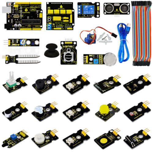
The smart home kit based on Arduino is newly issued by Keyestudieo company. The concept is to make people enjoy life. You could remotely control your assorted smart systems through your phone or computer when you’re out, like turning on air conditioner and water heater on the way home; the electronic door lock and led light will automatically run when you get home. Additionally, the intelligent lighting system can be used to select preset lighting scenes to create a comfortable and quiet atmosphere, which contributes to make your brain completely relaxed. You just need a remote control to finish all the process. What surprises you is that the smart system can save electricity as well. As Bill Gates puts it, in the future, homes without smart home systems will be as unfashionable as homes without internet access today. Let’s know more about smart home kit!
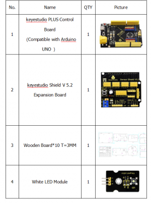
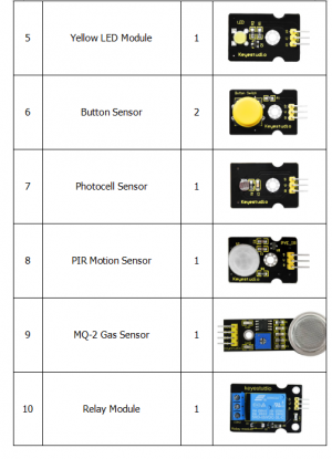
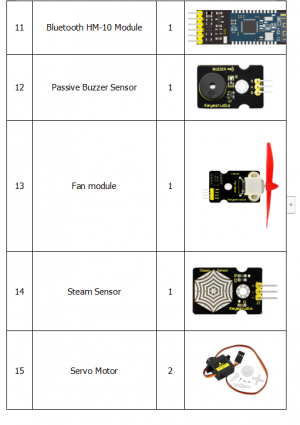
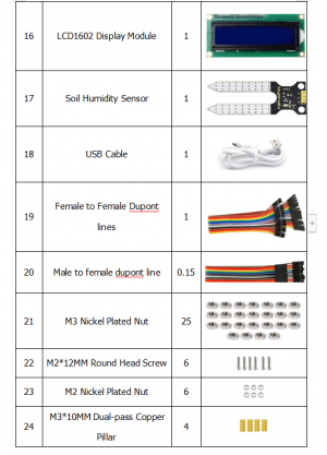
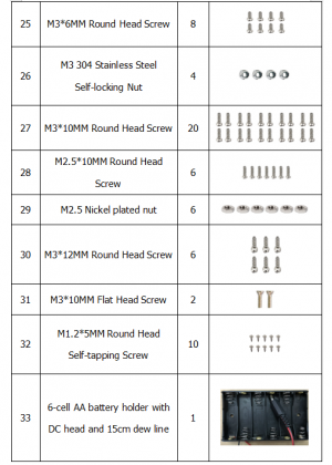
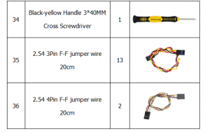
Kit List
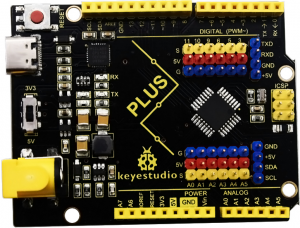
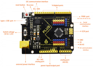
Keyestudio PLUS Control Board
Serial communication interface: D0 is RX, D1 is TX PWM interface (pulse width modulation): D3 D5 D6 D9 D10 D11 External interrupt interface: D2 (interrupt 0) and D3 (interrupt 1) SPI communication interface: D10 is SS, D11 is MOSI, D12 is MISO, D13 is SCK IIC communication port: A4 is SDA, A5 is SCL
Introduction:
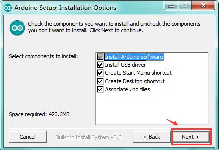
Install Arduino with the exe. Installation package you have downloaded well.
Get the latest version from the download page. You can choose between the Installer (.exe) and the Zip packages. We suggest you use the first one that installs directly everything you need to use the Arduino Software (IDE), including the drivers. With the Zip package you need to install the drivers manually. The Zip file is also useful if you want to create a portable installation.
When the download finishes, proceed with the installation and please allow the driver installation process when you get a warning from the operating system.
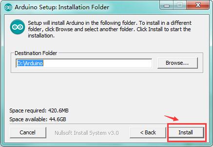
When the following interface appears, click Install to finish the installation.

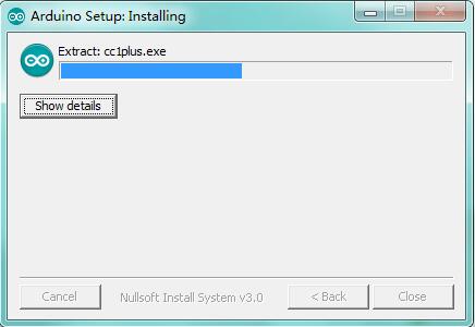
Finally, click “Close” after completing the installation.
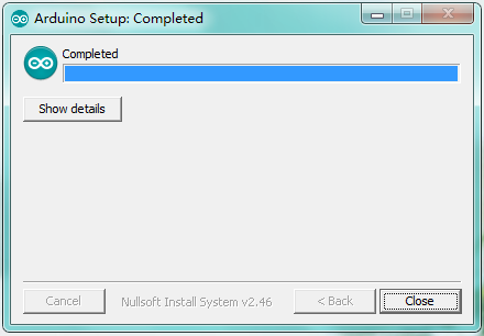
=
Installing Driver ===
Finish the download, now, let’s install the driver of keyestudio PLUS control board. Its chip is CP2102 serial chip.
(1)If download the Arduino1.8.x development software, the driver file is included in it.
Double click  , click to next step,as shown below:
Arduino IDE Setting
Keyestudio Sensor Shield V5.2
Description
In the experiments, you might often use ARDUINO control board and several sensor modules. If the interfaces of power output is not enough, you may need to add a breadboard and use many connection wires. Is it really troublesome?
But now, with this keyestudio sensor shield, you can easily solve that problem. This shield is fully compatible with keyestudio PLUS Control Board, so you can easily stack it onto PLUS Control Board.
This keyestudio sensor shield has extended the digital and analog ports out as 3PIN interface (G,V, S), which can directly connect 3PIN sensor modules.
It also breaks out some communication pins of 2.54mm pitch, like serial, IIC, and SPI communication.
The shield comes with a reset button and 2 signal indicators as well.
Additionally, you can supply the voltage needed to the sensor modules through blue terminal blocks on the shield. Because some sensor modules is not used with 5V or 3.3V but with special voltage.
Parameter:
- Extends an Arduino Reset button
- Comes with 1 electrolytic capacitor and 1 ceramic capacitor
- Comes with a built-in power indicator and a D13 indicator
- Breakout all the digital and analog ports of keyestudio PLUS Control Board as 3PIN headers
- A serial communication interface
- A I2C communication interface
- A SPI communication interface
- Comes with a URF interface
- Comes with an APC220 interface
- You can supply the voltage needed for sensor modules via terminal blocks
When SE is connected with jumper cap, and input DC 7V to VCC /GND terminal block, so the voltage of V, V1 and + pins are 7V. When SE is connected with jumper cap, and VCC /GND terminal block without voltage input, shield is powered via UNO R3, so the voltage of V, V1 and + pins are 5V. When SE is disconnected, input DC 7V to VCC /GND terminal block, so the voltage of V pin is 7V, the voltage of V1 and + pins are 0V. When SE is disconnected, and VCC /GND terminal block without voltage input, shield is powered via UNO R3, so the voltage of V pin is 0V, the voltage of V1 and + pins are 5V.
Example Use
Stack the Keyestudio Sensor Shield V5 on the Keyestudio PLUS Control Board, and build the circuit on the shield, as shown below.

Projects
When you get this kit, there are 14 sensors/modules inside like keyestudio PLUS control board, sensor shield and dupont Lines.
We firstly stack Keyestudio Sensor Shield V5.2 on the keyestudio PLUS control board and connect 14 sensors to sensor shield via dupont lines, upload the test code and check the result.
Note: In this course, the interface of each sensor / module marked with (G,-, GND) indicates the negative pole, and G and GND are connected to Arduino board or the sensor shield; V, +, and VCC stands for positive pole, they are linked with V, VCC and 5V of Arduino board or sensor shield.
Project 1: LED Blink
Description: In this kit, there are white and yellow LED modules. Their operating method is same. In this lesson, we directly connect the white LED module to the sensor shield with three female-to-female DuPont cables. After wiring, we can upload code on the keyestudio PLUS control board to control white LED to display different colors. After GND and VCC are powered on, the LED lights up when the signal terminal S is HIGH, and the LED turns off when signal end S is LOW.
Specifications:
- Control interface: digital port
- Working voltage: DC 3.3-5V
- Pin pitch: 2.54mm
- LED display color: white
- Size: 30 * 20mm
- Weight: 3g
Equipment:
- White LED module * 1
- Keyestudio PLUS Control Board * 1
- Sensor shield * 1
- 3pin female to female Dupont lines
- USB cable * 1
Connection Diagram:

Note: The G, V, and S ports of the white LED module are separately connected to G, V, and 13, then power on.
Test Code:
void setup()
{
  pinMode(13, OUTPUT);//set digital 13 to output}

void loop()
{
  digitalWrite(13,HIGH);//set digital 13 to HIGH level,LED lights up
  delay(1000);	//delay in 1000ms
  digitalWrite(13,LOW);//set digital13 to LOW level,LED lights off
  delay(1000);         //delay in 1000ms
}
Test Result: Upload the test code successfully. After power on, the white LED starts blinking, light up for 1,000ms, turn off for 1000ms,and alternately.
Project 2: LED Breathe
Description
In this project, we will control the red LED brightness via PWM.
In the previous course, we introduced how to control the yellow LED on and off by code. Similarly, you can change the step length and delay in the code to set the red LED to achieve different breathing effects.
PWM is a means of controlling the analog output via digital means. Digital control is used to generate square waves with different duty cycles (a signal that constantly switches between high and low levels) to control the analog output.In general, the input voltage of port are 0V and 5V. What if the 3V is required? Or what if switch among 1V,3V and 3.5V? We can’t change resistor constantly. For this situation, we need to control by PWM.
For the Arduino digital port voltage output, there are only LOW and HIGH, which correspond to the voltage output of 0V and 5V. You can define LOW as 0 and HIGH as 1, and let the Arduino output 500 0 or 1 signals within 1 second.
The output port is 2.5V, which is like showing movie. The movie we watch are not completely continuous. It actually outputs 25 pictures per second. In this case, the human can’t tell it. So does PWM. If want different voltage, need to control the ratio of 0 and 1. The more 0,1 signals output per unit time, the more accurate the control.
In the following figure, the green line represents a period, and its value is the reciprocal of the PWM frequency. In other words, if the frequency of the Arduino PWM is 500 Hz, then the period between the two green lines is 2 ms. The range that can be manipulated in the analogWrite () command is 0-255, analogWrite (255) means 100% duty cycle (normally open), and analogWrite (127) duty cycle is about 50% (half the time).
Specifications:
Control interface: digital port
Working voltage: DC 3.3-5V
Pin pitch: 2.54mm
LED display color: yellow
Size: 30 * 20mm
Weight: 3g
Equipment:
Yellow LED module * 1
Keyestudio PLUS Control Board * 1
Sensor shield * 1
3pin female to female DuPont lines
USB cable * 1
Connection Diagram:
Note: The G, V, and S ports of the yellow LED module are separately connected to G, V, and 13, then power on.
On the sensor expansion board, the G, V, and S pins of the yellow LED module are connected to G, V, and 5 respectively, and the power supply is connected.
Test Code:
 void setup(){
  analogWrite(5,0);//set the PWM value of digital5 to 0
}

void loop(){
  for (int i = 0; i <= 255; i = i + (51))
// variable i increases from 0 to 255, add 51 each time
{
    analogWrite(5,i);//set variable i to the PWM value of digital5
    delay(500);//delay in 500ms
  }
  for (int i = 255; i >= 0; i = i + (-51))
//variable i reduces from 255 to 0,plus -51 each time
 {
    analogWrite(5,i);//set variable i to the PWM value of digital5
    delay(500);//delay in 500ms
  }}
Test Result: Upload test code successfully and power on, yellow LED gradually become brighter and darker to simulate the human breath.
Project 3: Passive Buzzer
Description There are many interactive works that can be completed with Arduino. The most common element is buzzer and speaker. Buzzer is easy to use. And buzzer concludes in active buzzer and passive buzzer. In this project, we use passive buzzer. In this experiment, we make the buzzer sound and play music by test code.
Specifications:
Control Port: digital
Working Voltage: DC 3.3-5V
Equipment
Keyestudio PLUS Control Board * 1
Sensor shield * 1
Passive buzzer module * 1
USB cable * 1
3pin female to female Dupont cable * 1
Connection Diagram:
Note: The G, V, and S port of the passive buzzer module are separately connected to G, V, and 3 on the shield, power up.
Test Code:
 void setup(){
  pinMode(3, OUTPUT);//set digital3 to output
}

void loop(){
  tone(3,262);//digital3 outputs the sound of 262Hz
  delay(250);//delay in 250ms
  tone(3,294);;//digital3 outputs the sound of 294HZ
  delay(250);//delay in 250ms
  tone(3,330);
  delay(250);
  tone(3,349);
  delay(250);
  tone(3,392);
  delay(250);
  tone(3,440);
  delay(250);
  tone(3,494);
  delay(250);
  tone(3,532);
  delay(250);
  noTone(3);//digital3 turns off sound output
  delay(1000);
}
Test Result: Upload test code on keyestudio PLUS Control Board, wire according to connection diagram, passive buzzer sounds “do re mi fa so la si do”.
Project 4:Controlling LED By Button Module
Description: In this project, we will control LED to light on and off via button module. When the button is pressed, the signal end outputs low level (0); when released, the signal end of sensor keeps high level(1).
Specifications:
Working voltage: DC 3.3-5V
Control signal: digital signal
Size: 34 * 22 * 15mm
Weight: 3.8g
Equipment
Keyestudio REV4 development board * 1
Sensor shield * 1
Yellow LED module * 1
Button module * 1
USB cable * 1
3pin female to female DuPont Lines *2
Connection Diagram:
Note: The G, V, and S pins of button sensor module are separately connected to G, V, and 4 on the shield, and the G, V, and S pins of the yellow LED module are connected to G, V, and 5 on the shield.
Test Code:
void setup(){
  Serial.begin(9600);//set baud rate to 9600
  pinMode(4, INPUT);//set digital4 to input
  pinMode(5, OUTPUT);//set digital5 to output
}

void loop(){
  Serial.println(digitalRead(4));//wrap word and read the value of digital4
  delay(500);//delay in 500ms
  if (digitalRead(4) == 0)
//when read the value of digital4 to 0
 {
    digitalWrite(5,HIGH);//set digital5 to HIGH level, LED lights up
  }
else
//otherwise(when the value of digital4 is 1)
 {
    digitalWrite(5,LOW);//set digital5 to LOW level, LED lights off
}}
