KS0077(78,79)Super Learning Kit for Arduino: Difference between revisions
Keyestudio (talk | contribs) |
Keyestudio (talk | contribs) |
||
| Line 129: | Line 129: | ||
E- Used to save the sketch.<br> | E- Used to save the sketch.<br> | ||
F- Used to send the serial data received from board to the serial monitor.<br> | F- Used to send the serial data received from board to the serial monitor.<br> | ||
=== Start your first program === | |||
Open the file to select Example, choose BLINK from BASIC, as shown below: | |||
<br>[[Image:048610png.png|500px|frameless]]<br> | |||
<br>[[Image:048611png.png|500px|frameless]]<br> | |||
Set board and COM port, the corresponding board and COM port are shown on the lower right of IDE. | |||
<br>[[Image:048612png.png|500px|frameless]]<br> | |||
Click [[Image:0486-20.png|50px|frameless]] to start compiling the program, check errors. | |||
<br>[[Image:048613png.png|500px|frameless]]<br> | |||
Click [[Image:0486-23.png|50px|frameless]]to upload the program, upload successfully. | |||
<br>[[Image:048614png.png|500px|frameless]]<br> | |||
Upload the program successfully, the onboard LED lights on for 1s, lights off for 1s. Congratulation, you finish the first program. | |||
Revision as of 12:28, 17 November 2020
Introduction
keyestudio super learning kit is suitable for Arduino enthusiasts. This kit includes 32 projects with detailed tutorials, starting from the basics to more complex projects. Different from other kits, it adds some functional modules, such as RFID, temperature and humidity module. There is connection diagram and code for each project, making it easy for you to learn.
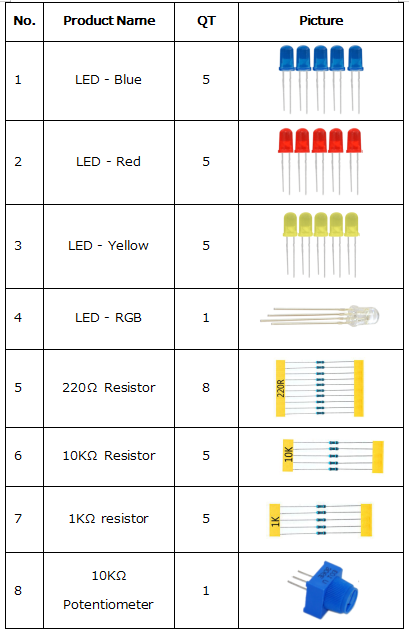
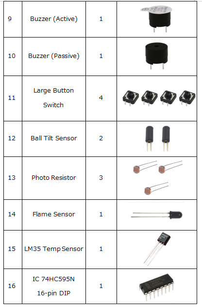
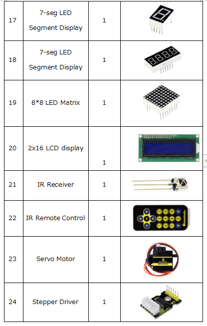
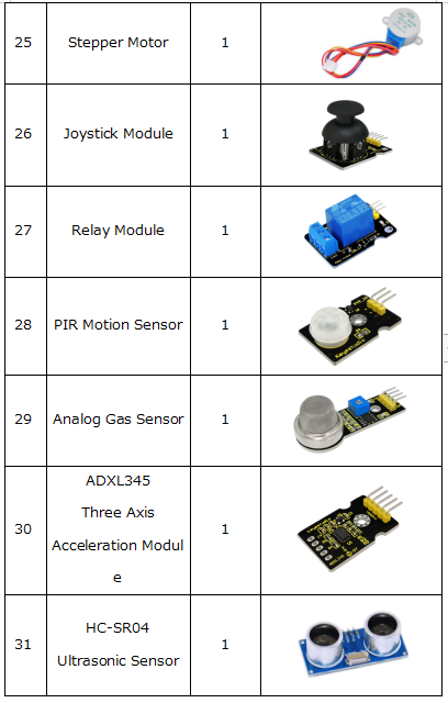
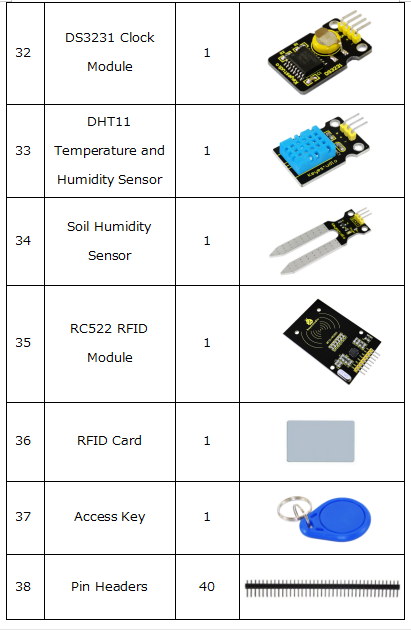
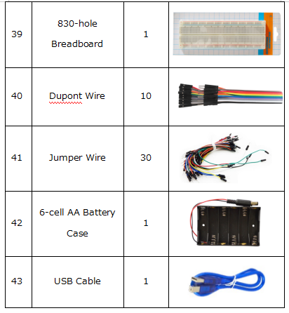
Component List
NOTE KS0077 Kit Not Includes Main board; KS0078 Kit Includes V4.0 board; KS0079 KIT Includes MEGA 2560 board.
Install Arduino IDE and Driver
Download software
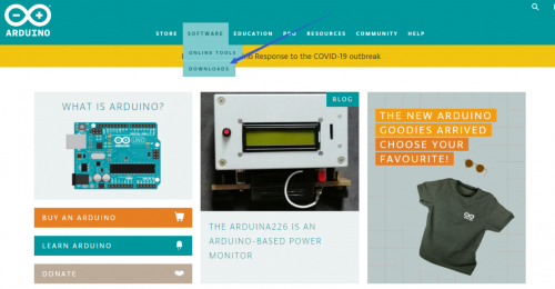
When we get control board, we need to download Arduino IDE and driver firstly. You could download Arduino IDE from the official website: https://www.arduino.cc/, click the SOFTWARE on the browse bar, click “DOWNLOADS” to enter download page, as shown below:
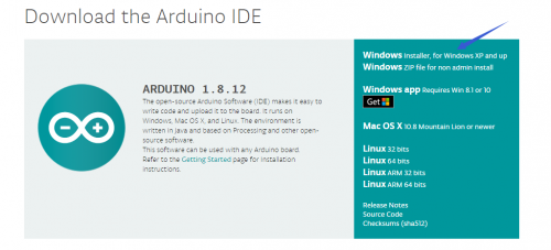
There are various versions for Arduino, just download a suitable version for your system, we will take WINDOWS system as an example to show you how to download and install.
There are two versions for WINDOWS system, one is installed version, another one is download version, you just need to download file to computer directly and unzip it. These two versions can be used normally. Choose one and download on your computer.
You just need to click JUST DOWNLOAD, then click the downloaded file to install it. And when the ZIP file is downloaded, you can directly unzip and start it.
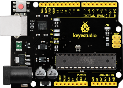
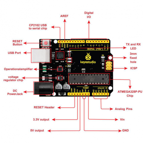
Keyestudio V4.0 Development Board
We need to know keyestudio V4.0 development board, as a core of this smart car.
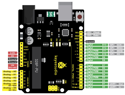
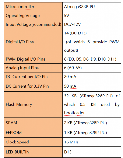
keyestudio V4.0 development board is an Arduino uno-compatible board, which is based on ATmega328P MCU, and with a cp2102 Chip as a UART-to-USB converter.
It has 14 digital input/output pins (of which 6 can be used as PWM outputs), 6 analog inputs, a 16 MHz quartz crystal, a USB connection, a power jack, 2 ICSP headers and a reset button.
It contains everything needed to support the microcontroller; simply connect it to a computer with a USB cable or power it via an external DC power jack (DC 7-12V) or via female headers Vin/ GND(DC 7-12V) to get started.
Keyestudio MEGA 2560 Board
Keyestudio Mega 2560 R3 is a microcontroller board based on the ATMEGA2560-16AU , fully compatible with ARDUINO MEGA 2560 R3. 图
It has 54 digital input/output pins (of which 15 can be used as PWM outputs), 16 analog inputs, 4 UARTs (hardware serial ports), a 16 MHz crystal oscillator, a USB connection, a power jack, 1 ICSP header, and a reset button. The built-in ICSP port can burn the firmware for ATMEGA2560-16AU directly. This chip is burnt the firmware well before leaving the factory, therefore, we hardly use it. We can power on by USB wire, DC head and Vin GND pins. To facilitate wiring, a 0.5 m USB wire is provided for you.
图
Specialized Functions of Some Pins: 1. Serial Communication: D0 (RX0) and D1 (TX1); Serial 1: D19 (RX1) and D18 (TX1); Serial 2: D17 (RX2) and D16 (TX2); Serial 3: D15 (RX3) and D14 (TX3). Used to receive (RX) and transmit (TX) TTL serial data. Pins 0 and 1 are also connected to the corresponding pins of the CP2102 USB-to-TTL Serial chip. 2. PWM Pins (Pulse-Width Modulation): D2 to D13, and D44 to D46. Provide 8-bit PWM output with the analogWrite() function. 3. External Interrupts: D2 (interrupt 0), D3 (interrupt 1), D18 (interrupt 5), D19 (interrupt 4), D20 (interrupt 3), and D21 (interrupt 2). These pins can be configured to trigger an interrupt on a low level, a rising or falling edge, or a change in level. See the attachInterrupt() function for details. 4. SPI communication: D53 (SS), D52 (SCK), D51 (MOSI), D50 (MISO). These pins support SPI communication using theSPI library. The SPI pins are also broken out on the ICSP header, which is physically compatible with the Arduino Uno. 5. IIC communication: D20 (SDA); D21 (SCL). Support TWI communication using the Wire library.
Installing driver
Let’s install the driver of keyestudio PLUS control board. The USB-TTL chip on PLUS board adopts CP2102 serial chip. The driver program of this chip is included in Arduino 1.8 version and above, which is convenient. Plug on USB port of board, the computer can recognize the hardware and automatically install the driver of CP2102.
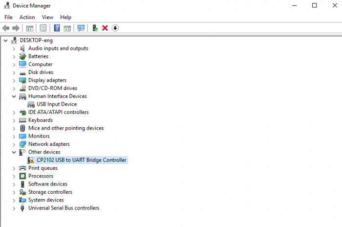
If install unsuccessfully, or you intend to install manually, open the device manager of computer. Right click Computer----- Properties----- Device Manager.
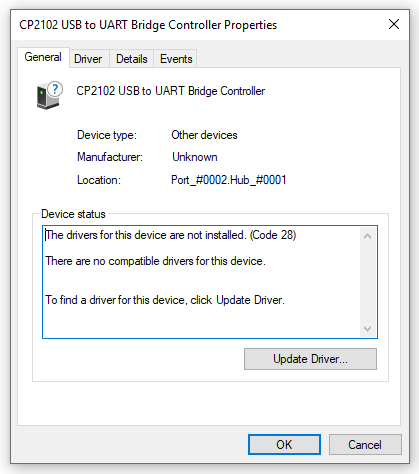
There is a yellow exclamation mark on the page, which implies installing the driver of CP2102 unsuccessfully. Then we double click the hardware and update the driver.
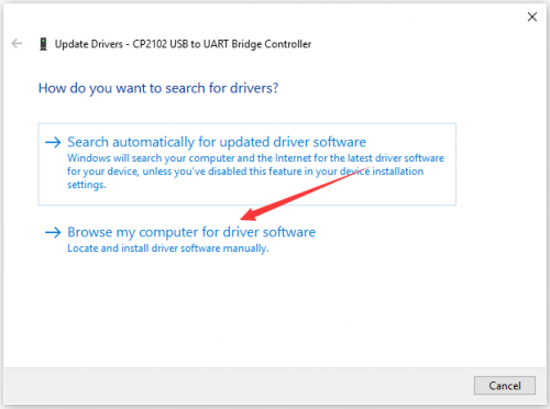
Click “OK” to enter the following page, click “browse my computer for updated driver software”, find out the installed or downloaded ARDUINO software. As shown below:
There is a DRIVERS folder in Arduino software installed package(![]() ), open driver folder and you can see the driver of CP210X series chips.
), open driver folder and you can see the driver of CP210X series chips.
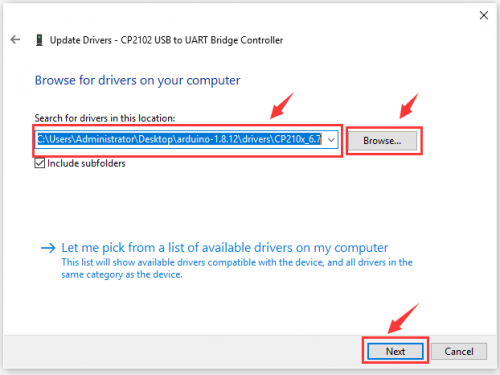
We click “Browse”, then find out the driver folder, or you could enter “driver” to search in rectangular box, then click “next”, the driver will be installed successfully. (I place Arduino software folder on the desktop, you could follow my way)
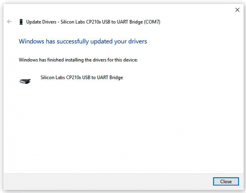
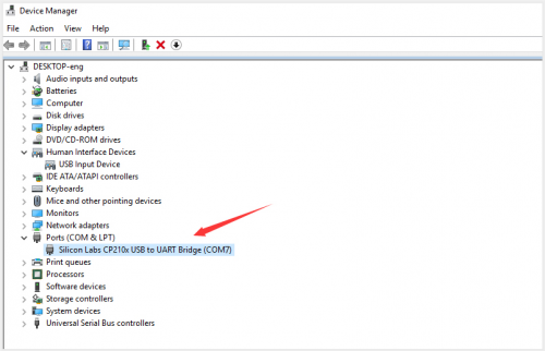
Open device manager, we will find the yellow exclamation mark disappear. The driver of CP2102 is installed successfully.
Arduino IDE Setting
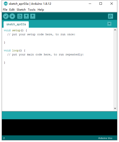
To avoid the errors when uploading the program to the board, you need to select the correct Arduino board that matches the board connected to your computer.
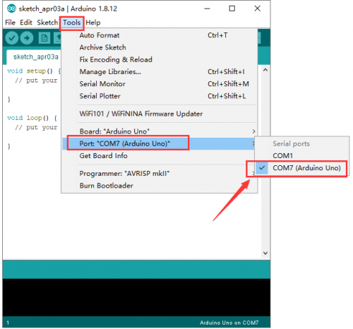
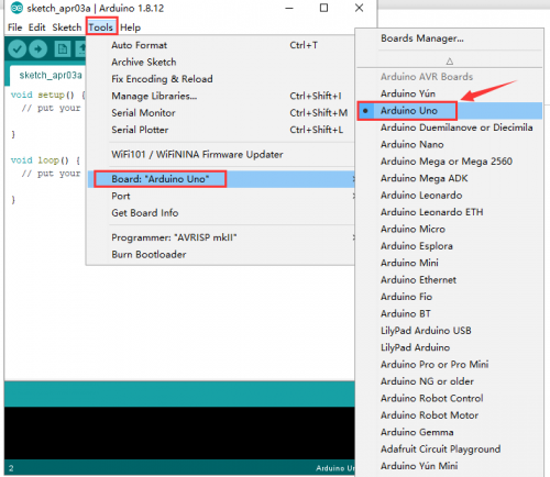
Then come back to the Arduino software, you should click Tools→Board, select the board. (as shown below)
Then select the correct COM port (you can see the corresponding COM port after the driver is successfully installed)
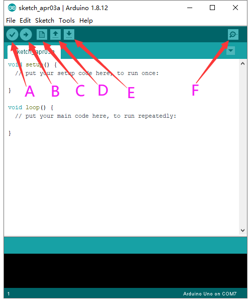
Before uploading the program to the board, let’s demonstrate the function of each symbol in the Arduino IDE toolbar.
A- Used to verify whether there is any compiling mistakes or not.
B- Used to upload the sketch to your Arduino board.
C- Used to create shortcut window of a new sketch.
D- Used to directly open an example sketch.
E- Used to save the sketch.
F- Used to send the serial data received from board to the serial monitor.
Start your first program
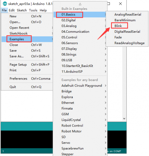
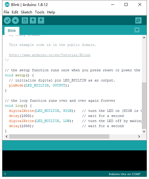
Open the file to select Example, choose BLINK from BASIC, as shown below:
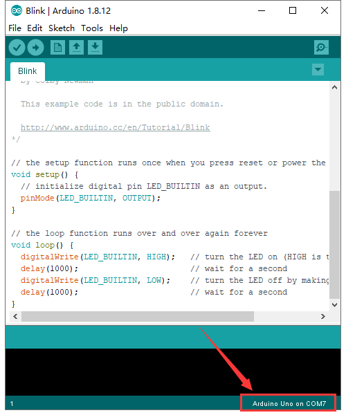
Set board and COM port, the corresponding board and COM port are shown on the lower right of IDE.
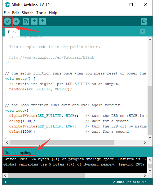
Click ![]() to start compiling the program, check errors.
to start compiling the program, check errors.
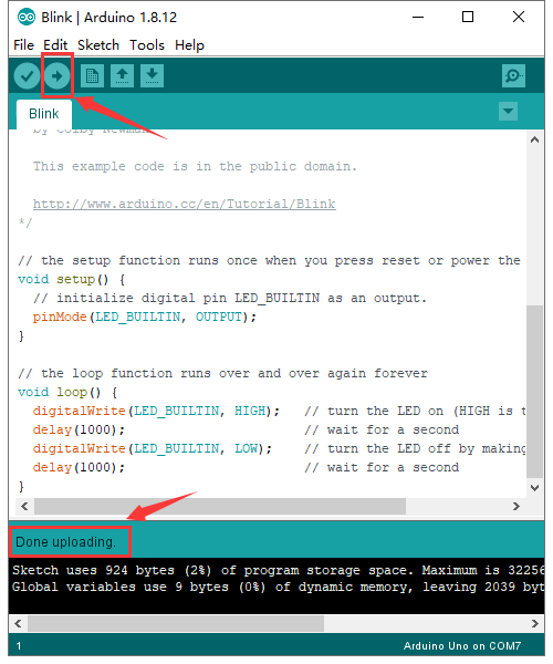
Click ![]() to upload the program, upload successfully.
to upload the program, upload successfully.
Upload the program successfully, the onboard LED lights on for 1s, lights off for 1s. Congratulation, you finish the first program.
