KS0217 keyestudio RPI Dot Matrix: Difference between revisions
Keyestudio (talk | contribs) (Created page with "==keyestudio RPI Dot Matrix== <br>500px|frameless|thumb<br> ==Introduction== We are know that the I/O Pin of Raspberry Pi is limited. So Raspberry come...") |
Keyestudio (talk | contribs) |
||
| Line 1: | Line 1: | ||
==keyestudio RPI Dot Matrix== | ==keyestudio RPI Dot Matrix== | ||
<br>[[File: | <br>[[File:ks0216-1.png|500px|frameless|thumb]]<br> | ||
==Introduction== | ==Introduction== | ||
Revision as of 11:36, 11 February 2017
keyestudio RPI Dot Matrix
Introduction
We are know that the I/O Pin of Raspberry Pi is limited. So Raspberry come with LED dot matrix screen, it would be more trouble. But use special LED constant current control chip, basically only takes Raspberry Pi SPI interface (3 IO + 2 enabled) you can control 64 LED lights. LED dot matrix drivers became possible! This product is a dot-matrix-led-display module, which compatible with any version of Raspberry Pi. We will provide installation package, source code and quickstart guide PDF. We will teach you step by step, so don’t worry!
Specification
Support all versions of Raspberry Pi Driver Chip : MAX7219 Dot Matrix Type: 8x8 common cathode red dot matrix Matrix Size:64.3*35.0*26.5mm
Connection Diagram
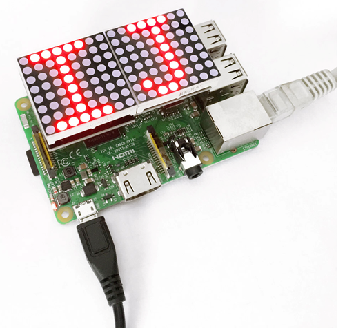
Plug it directly into Raspberry Pi to start your works as shown in below figure.

Sample Code
// blink.c
//
// Example program for bcm2835 library
// Blinks a pin on an off every 0.5 secs
//
// After installing bcm2835, you can build this
// with something like:
// make or gcc -o led led.c -lbcm2835
// sudo ./led
/*
             define from bcm2835.h                       define from Board DVK511
                 3.3V | | 5V               ->                 3.3V | | 5V
    RPI_V2_GPIO_P1_03 | | 5V               ->                  SDA | | 5V
    RPI_V2_GPIO_P1_05 | | GND              ->                  SCL | | GND
       RPI_GPIO_P1_07 | | RPI_GPIO_P1_08   ->                  IO7 | | TX
                  GND | | RPI_GPIO_P1_10   ->                  GND | | RX
       RPI_GPIO_P1_11 | | RPI_GPIO_P1_12   ->                  IO0 | | IO1
    RPI_V2_GPIO_P1_13 | | GND              ->                  IO2 | | GND
       RPI_GPIO_P1_15 | | RPI_GPIO_P1_16   ->                  IO3 | | IO4
                  VCC | | RPI_GPIO_P1_18   ->                  VCC | | IO5
       RPI_GPIO_P1_19 | | GND              ->                 MOSI | | GND
       RPI_GPIO_P1_21 | | RPI_GPIO_P1_22   ->                 MISO | | IO6
       RPI_GPIO_P1_23 | | RPI_GPIO_P1_24   ->                  SCK | | CE0
                  GND | | RPI_GPIO_P1_26   ->                  GND | | CE1

::if your raspberry Pi is version 1 or rev 1 or rev A
RPI_V2_GPIO_P1_03->RPI_GPIO_P1_03
RPI_V2_GPIO_P1_05->RPI_GPIO_P1_05
RPI_V2_GPIO_P1_13->RPI_GPIO_P1_13:

*/
#include <bcm2835.h>
#include <stdio.h>
#define uchar unsigned char
#define uint unsigned int


//#define Max7219_pinCLK  RPI_GPIO_P1_11
#define Max7219_pinCS  RPI_GPIO_P1_24
//#define Max7219_pinDIN  RPI_V2_GPIO_P1_13

uchar disp1[38][8] = {
{0x3C,0x42,0x42,0x42,0x42,0x42,0x42,0x3C},//0
{0x10,0x30,0x50,0x10,0x10,0x10,0x10,0x7C},//1
{0x3E,0x02,0x02,0x3E,0x20,0x20,0x3E,0x00},//2
{0x00,0x7C,0x04,0x04,0x7C,0x04,0x04,0x7C},//3
{0x08,0x18,0x28,0x48,0xFE,0x08,0x08,0x08},//4
{0x3C,0x20,0x20,0x3C,0x04,0x04,0x3C,0x00},//5
{0x3C,0x20,0x20,0x3C,0x24,0x24,0x3C,0x00},//6
{0x3E,0x22,0x04,0x08,0x08,0x08,0x08,0x08},//7
{0x00,0x3E,0x22,0x22,0x3E,0x22,0x22,0x3E},//8
{0x3E,0x22,0x22,0x3E,0x02,0x02,0x02,0x3E},//9
{0x08,0x14,0x22,0x3E,0x22,0x22,0x22,0x22},//A
{0x3C,0x22,0x22,0x3E,0x22,0x22,0x3C,0x00},//B
{0x3C,0x40,0x40,0x40,0x40,0x40,0x3C,0x00},//C
{0x7C,0x42,0x42,0x42,0x42,0x42,0x7C,0x00},//D
{0x7C,0x40,0x40,0x7C,0x40,0x40,0x40,0x7C},//E
{0x7C,0x40,0x40,0x7C,0x40,0x40,0x40,0x40},//F
{0x3C,0x40,0x40,0x40,0x40,0x44,0x44,0x3C},//G
{0x44,0x44,0x44,0x7C,0x44,0x44,0x44,0x44},//H
{0x7C,0x10,0x10,0x10,0x10,0x10,0x10,0x7C},//I
{0x3C,0x08,0x08,0x08,0x08,0x08,0x48,0x30},//J
{0x00,0x24,0x28,0x30,0x20,0x30,0x28,0x24},//K
{0x40,0x40,0x40,0x40,0x40,0x40,0x40,0x7C},//L
{0x81,0xC3,0xA5,0x99,0x81,0x81,0x81,0x81},//M
{0x00,0x42,0x62,0x52,0x4A,0x46,0x42,0x00},//N
{0x3C,0x42,0x42,0x42,0x42,0x42,0x42,0x3C},//O
{0x3C,0x22,0x22,0x22,0x3C,0x20,0x20,0x20},//P
{0x1C,0x22,0x22,0x22,0x22,0x26,0x22,0x1D},//Q
{0x3C,0x22,0x22,0x22,0x3C,0x24,0x22,0x21},//R
{0x00,0x1E,0x20,0x20,0x3E,0x02,0x02,0x3C},//S
{0x00,0x3E,0x08,0x08,0x08,0x08,0x08,0x08},//T
{0x42,0x42,0x42,0x42,0x42,0x42,0x22,0x1C},//U
{0x42,0x42,0x42,0x42,0x42,0x42,0x24,0x18},//V
{0x00,0x49,0x49,0x49,0x49,0x2A,0x1C,0x00},//W
{0x00,0x41,0x22,0x14,0x08,0x14,0x22,0x41},//X
{0x41,0x22,0x14,0x08,0x08,0x08,0x08,0x08},//Y
{0x00,0x7F,0x02,0x04,0x08,0x10,0x20,0x7F},//Z
{0x08,0x7F,0x49,0x49,0x7F,0x08,0x08,0x08},//中{0xFE,0xBA,0x92,0xBA,0x92,0x9A,0xBA,0xFE},//国
};
void Delay_xms(uint x)
{

 bcm2835_delay(x);

}
//------------------------
void Write_Max7219_byte(uchar DATA)
{
         uchar i ;
         bcm2835_gpio_write(Max7219_pinCS,LOW);
       /* for(i = 8; i >= 1; i--)
            {
             bcm2835_gpio_write(Max7219_pinCLK,LOW);
             bcm2835_gpio_write( Max7219_pinDIN, (DATA & 0x80));
             DATA = DATA << 1;
             bcm2835_gpio_write(Max7219_pinCLK,HIGH);
            }
	   */
      bcm2835_spi_transfer(DATA);

}
void Write_Max7219(uchar address1,uchar dat1,uchar address2,uchar dat2)
//void Write_Max7219(uchar address,uchar dat)
{
  bcm2835_gpio_write(Max7219_pinCS,LOW);

  Write_Max7219_byte(address1);
  Write_Max7219_byte(dat1);
  Write_Max7219_byte(address2);
  Write_Max7219_byte(dat2);
   //_nop_();
  //Write_Max7219_byte(address);
  //Write_Max7219_byte(dat);
  bcm2835_gpio_write(Max7219_pinCS,HIGH);
}

void Init_MAX7219(void)
{
 Write_Max7219(0x09,0x00,0x09,0x00);
 Write_Max7219(0x0a,0x03,0x0a,0x03);
 Write_Max7219(0x0b,0x07,0x0b,0x07);
 Write_Max7219(0x0c,0x01,0x0c,0x01);
 Write_Max7219(0x0f,0x00,0x0f,0x00);
}

/*void Init_MAX7219(void)
{
 Write_Max7219(0x09,0x00);
 Write_Max7219(0x0a,0x03);
 Write_Max7219(0x0b,0x07);
 Write_Max7219(0x0c,0x01);
 Write_Max7219(0x0f,0x00);
}
*/

int main(void)
{
 uchar i , j;
 if (!bcm2835_init())
        return 1;
 bcm2835_spi_begin();
 bcm2835_spi_setBitOrder(BCM2835_SPI_BIT_ORDER_MSBFIRST);      // The default
 bcm2835_spi_setDataMode(BCM2835_SPI_MODE0);                   // The default
 bcm2835_spi_setClockDivider(BCM2835_SPI_CLOCK_DIVIDER_256); // The default


  bcm2835_gpio_fsel(Max7219_pinCS, BCM2835_GPIO_FSEL_OUTP);

  bcm2835_gpio_write(disp1[j][i],HIGH);

 Delay_xms(50);
 Init_MAX7219();
 while(1)
 {
  for(j = 0;j <37; j++)
  {
   for(i = 1;i < 9;i++)
     Write_Max7219(i , disp1[j+1][i-1],i,disp1[j][i-1]);
     Delay_xms(1000);
  }
 }
  bcm2835_spi_end();
  bcm2835_close();
  return 0;
}
Program Writing
1.Installing bcm-2835 Library
Here is the tutorial for installing bcm-2835 library in Raspberry Pi. To install bcm-2835, first we need to download bcm2835 library. So we will provide an installation package or click its office web http://www.airspayce.com/mikem/bcm2835/ to download it. Step1:- Now after downloading library, copy it in any folder of your raspberry pi by winSCP(we provide its installation package, but please refer to usage by yourselves). Step2:- Now it’s time to extract the library, so open terminal of raspberry pi and go to the folder where you have copied your library and type this command: tar zxvf bcm2835-1.26.tar.gz Step3:- Now to into library folder, type this command: cd bcm2835-1.26 Step4:- Now, we are ready to install bcm2835 library, so to start installation type this command: ./configure Step5:- then type this command: make Step6:- then this: sudo make check Step7:- and finally this: sudo make install Congrats your library is installed. Now use “#include <bcm2835.h>” in your program to use bcm2835 library.
2.Programming
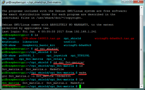
Now its time to write a program. Copy the file rpi_Dot-matrix provided by us and put it into the directory rpi_shield through winSCP. Next , type this command: cd rpi_Dot-matrix to go inside the rpi_Dot-matrix folder. Then type this command: make to make an executable file. This means this is the file we run to launch the program as shown in below figure. Finally type this: sudo ./Dot_matrix to launch the program. br>
3.Programming
Copy the file pcf8591 provided by us and put it into your pi directory through winSCP. Next , type this command: cd pcf8591 to go inside the pcf8591 folder. Then type this command: make to make an executable file. This means this is the file we run to launch the program.
Finally type this: sudo ./TTP229 to launch the program.

Result
The dot matrix will display letters “IJ” as shown in below figure. Use Ctrl+C to exit the processing program.

