KS0511 Keyestudio Quick Connectors Ultrasonic Module(CS100A Chip/Black/Environment-friendly): Difference between revisions
Keyestudio (talk | contribs) No edit summary |
Keyestudio (talk | contribs) No edit summary |
||
| Line 91: | Line 91: | ||
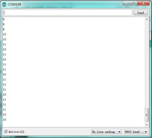
After wiring it up, burning the code and opening the serial monitor to set the baud rate to 9600, you can see the distance value between the ultrasonic sensor and the obstacle on the display as shown below. | After wiring it up, burning the code and opening the serial monitor to set the baud rate to 9600, you can see the distance value between the ultrasonic sensor and the obstacle on the display as shown below. | ||
<br>[[File: | <br>[[File:2003-3.png|500px|frameless|thumb]]<br> | ||
Latest revision as of 08:59, 8 July 2021
Description
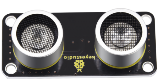
This ultrasonic module, equipped with the CS100A chip , is of high performance and low cost and boasts a wide voltage range from 3.3V to 5V. It can measure distance from 4cm to 300 cm with high accuracy and stability so as to be well applied in distance measurements, robots, anti-theft devices and others.
Working Principle:
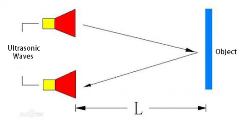
(1)Use trig Port to trigger 10us high level signals;

(2)Automatically send eight square waves of 40khz out and detect if there are signals sent back.
![]()
(3)If there are signals back, output a high level via echo. Then the time lasting for high level is the time gap between the transmission and reception of the signals.
Measured distance(L) =(high level time* the speed of time(340M/S))/2.
Parameters:
- Working voltage: 3.3-5V (DC)
- Work current: 50MA-100MA,usually 65mA
- Interface: 2.54mm 4PIN
- Working frequency: 40KHz
- Maximum distance: 300cm
- Minimum distance: 4cm
- Measurement angle: 15 degrees
- Trigger input signal: 10μs TTL pulse
- Output signals: digital signals
- Size: 49 * 22 * 19mm
- Weight: 9.2g
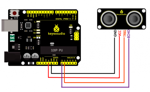
Connection Diagram
Test Code
- define echoPin 4 // Echo Pin
- define trigPin 3// Trigger Pin
- define LEDPin 13 // Onboard LED
int maximumRange = 200; // Maximum range needed int minimumRange = 0; // Minimum range needed long duration, distance; // Duration used to calculate distance
void setup() {
Serial.begin (9600);
pinMode(trigPin, OUTPUT);
pinMode(echoPin, INPUT);
pinMode(LEDPin, OUTPUT); // Use LED indicator (if required)
}
void loop() { /* The following trigPin/echoPin cycle is used to determine the
distance of the nearest object by bouncing soundwaves off of it. */
digitalWrite(trigPin, LOW);
delayMicroseconds(2);
digitalWrite(trigPin, HIGH);
delayMicroseconds(10);
digitalWrite(trigPin, LOW);
duration = pulseIn(echoPin, HIGH);
 //Calculate the distance (in cm) based on the speed of sound.
distance = duration/58.2;
 if (distance >= maximumRange || distance <= minimumRange){
/* Send a negative number to computer and Turn LED ON
to indicate "out of range" */
Serial.println("-1");
digitalWrite(LEDPin, HIGH);
}
else {
/* Send the distance to the computer using Serial protocol, and
turn LED OFF to indicate successful reading. */
Serial.println(distance);
digitalWrite(LEDPin, LOW);
}

//Delay 50ms before next reading.
delay(50);
}
Test Results:
After wiring it up, burning the code and opening the serial monitor to set the baud rate to 9600, you can see the distance value between the ultrasonic sensor and the obstacle on the display as shown below.


