KS0221 keyestudio Ultimate Starter Kit for Raspberry Pi: Difference between revisions
Keyestudio (talk | contribs) |
Keyestudio (talk | contribs) |
||
| Line 348: | Line 348: | ||
== Learning Courses == | == Learning Courses == | ||
=== Lesson 1: Hello World === | === Lesson 1: Hello World === | ||
| Line 364: | Line 365: | ||
'''e.''' In the terminal execute '''sudo. / HelloWorld''' to run the file, the terminal will print Hello World! as the figure shown below. <br> | '''e.''' In the terminal execute '''sudo. / HelloWorld''' to run the file, the terminal will print Hello World! as the figure shown below. <br> | ||
'''f.''' Ctrl + c exits the processing program. | '''f.''' Ctrl + c exits the processing program. | ||
<br>[[File:Lesson1.png| | <br>[[File:Lesson1.png|700px|frameless|thumb]]<br> | ||
'''4. Sample Code''' | '''4. Sample Code''' | ||
| Line 397: | Line 398: | ||
Target is usually the name of the file to be generated; Prerequiries is the material to generate the target; <tab> Command is a command to execute a target. <br> | Target is usually the name of the file to be generated; Prerequiries is the material to generate the target; <tab> Command is a command to execute a target. <br> | ||
When executing the make command in the folder, the system's compiler will generate the executable HelloWorld file according to the instructions in the Malefile file. Executing HelloWorld file, more Makefile knowledge please refer to the relevant information. | When executing the make command in the folder, the system's compiler will generate the executable HelloWorld file according to the instructions in the Malefile file. Executing HelloWorld file, more Makefile knowledge please refer to the relevant information. | ||
=== Lesson 2: LED Blinking === | === Lesson 2: LED Blinking === | ||
Revision as of 08:22, 10 August 2018
keyestudio Ultimate Starter Kit for Raspberry Pi
Kit Introduction
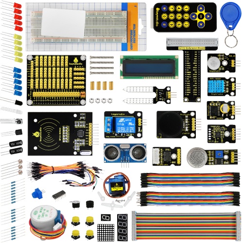
Raspberry Pi is a delicate card computer. This is a starter kit of Raspberry Pi, very suitable for zero-based raspberry pi enthusiasts. Through this kit, you can learn more about the knowledge of linux operating system, as well as C, python and other language programming based on the debian system of Raspberry Pi. This kit also provides you with some related sensors and modules applied to the Raspberry Pi.
We offer richer learning materials that allow you to learn about Raspberry Pi from scratch. The learning materials include the installation and usage of the Raspberry Pi related system, where also offer you the learning courses of Raspberry Pi collocated with some commonly used sensors and modules. It would be better If you are an arduino hobbyist because arduino and Raspberry Pi are the best partners. You can make more creative DIY works via arduino strong community support and rich third-party library resources, integrating into Raspberry Pi's powerful function support to motivate your creativity and inspiration!
Kit List
Kit Contents
Lesson 1: Hello World
Lesson 2: LED Blinking
Lesson 3: Breathing LED
Lesson 4: Traffic Light
Lesson 5: LED Chasing Effect
Lesson 6: Button-controlled LED
Lesson 7: Passive Buzzer
Lesson 8: Active Buzzer
Lesson 9: Responder
Lesson 10: Flame Sensor
Lesson 11: Ball Tilt Sensor
Lesson 12: IR Remote Control
Lesson 13: 1-digit LED Segment Display
Lesson 14: 74HC595
Lesson 15: 4-digit LED Segment Display
Lesson 16: LED Matrix Display
Lesson 17: 1602 LCD
Lesson 18: RGB LED
Lesson 19: 9g Servo Control
Lesson 20: ULN2003 Stepper Motor
Lesson 21: Photo Resistor
Lesson 22: LM35 Temp Sensor
Lesson 23: pcf8591
Lesson 24: PIR Motion Sensor
Lesson 25: MQ-2 Analog Gas Sensor
Lesson 26: ADXL345 Acceleration Module
Lesson 27: Ultrasonic Sensor
Lesson 28: Joystick Module
Lesson 29: 5V Relay
Lesson 30: DHT11 Temp and Humidity Sensor
Lesson 31: Soil Humidity Sensor
Lesson 32: DS3231 Clock Module
System Programming & Corresponding Tool Library Installation
1. Format the TFT card:
a. Plug the TFT card into the USB port through the card reader, open and install the SDFormatter tool in tool folders we provided. Open the tool as the figure shown below:

Tool Website: https://www.sdcard.org/downloads/formatter_4/index.html
b. The Driver in the upper figure: G is the TFT card just inserted. If you have several other TFT cards inserted in the computer, you can pass the drop-down menu to select the TFT card that needs to be formatted. And then click "Format",it will automatically format the TFT card. The formatting process will pop up the warning as shown below, then click OK.
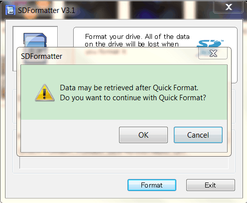
c. The picture below shows the successful format of the TFT card:
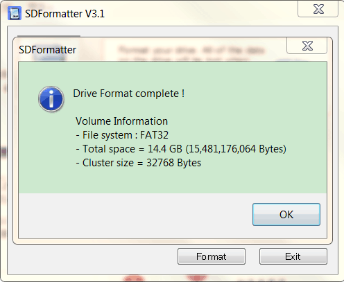
2. Program Raspberry Mirror Image:
a. Open the Win32DiskImager in tool folder we provided, open the tool as the following figure shown:
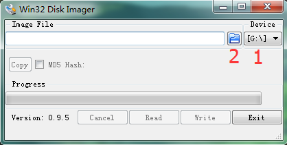
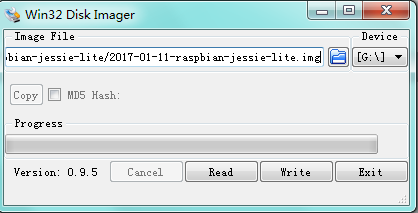
b. Click marked 1 to select the formatted TFT card, then click marked 2 to choose the system image file "2017-01-11-raspbian-jessie-lite" in the raspberry image folder we provided. The figure shown as below:
Raspberry Pi Download Address:https://www.raspberrypi.org/downloads/
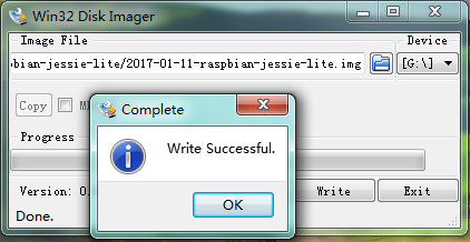
c. The above steps are configured well and click “Write”, it will automatically program the raspberry mirror image to the TFT card, and you need to wait for a few minutes in this process. Below shows the Write Successful. Then click “OK “ to unplug the TFT card.
Log into Raspberry
1. Log into Raspberry via SSH
a. Insert TFT card burning well the system into Raspberry board. Internet interface of the motherboard is connected to LAN via the network cable, and the mini USB port on the motherboard is powered by an external power supply.
Then, use Advanced IP Scanner software,click  ,find the corresponding IP address of the raspberry pi, as shown below:

When logging in by SSH, you first need to put an ssh file in the system root directory, as shown below:
![]()
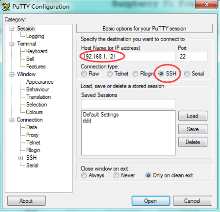
b. Open the PUTTY tool in the folder tool, only set two places of red circle as the figure shown below, the other places not to be set, and then click "Open" to log in.
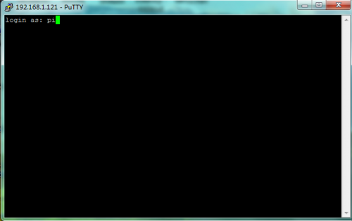
Username for the initial login in Raspberry system: pi
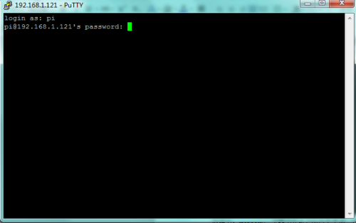
Password: raspberry
Logging in Raspberry system for the first time, it is best to expand the root partition to the entire TFT card, then on the terminal please input: sudo raspi-config
It will appear the following window after execution:
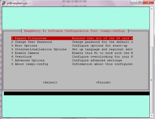
Then, select 1 Expand Filesystem through the keyboard’s "↑↓"key, and click “Enter” key on the keyboard. Then through the "→ ←"key to select “Finish”, and click the “Enter” key on the keyboard. Finally, pop up the following window, then click “Yes”.
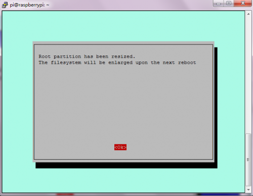
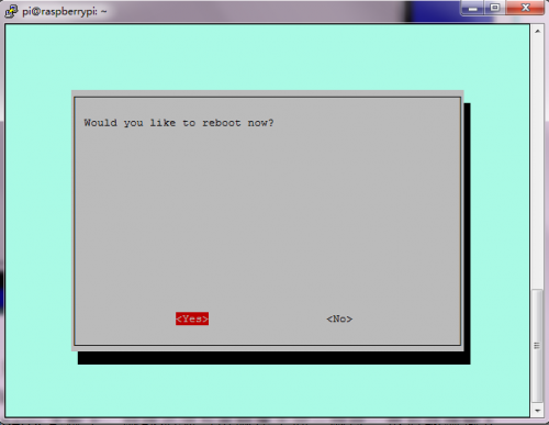
After click Yes, it has rebooted the Raspberry, so you just need to re-login it.
2. Using WinSCP to transfer file between PC host and Raspberry
a. Plug the network cable of the router into the Raspberry motherboard, and network cable must belong to the same network segment with the computer.
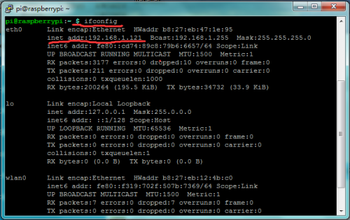
Then input ifconfig command in the terminal to check the Raspberry’s IP, and the IP at this moment is 192.168.1.121 as shown in the following figure:
b. Open the folder tool where provides a WinSCP installation package, then install and open the application program, the window interface shown as the figure below:
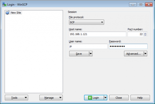
c. File protocol is SCP; Host name is Raspberry’s IP address; Default port number is 22; Username is pi; Password is raspberry.
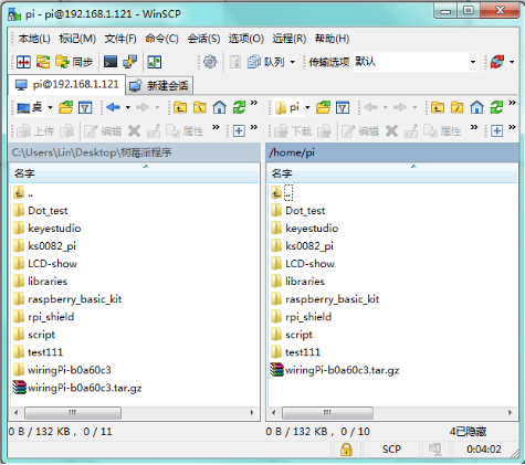
Then click “Login”, if the login process appears prompts, click “Yes”. Appearing the below figure means successfully log in WinSCP.
3. Install Wiringpi
a. Wiringpi is a library file for raspberry to control IO port, in which integrates I2C library, SPI library, UART library, software PWM library and more.
The relevant library function folder provides the compression package of wiringpi library file.
Or you can download it on the official website: https://projects.drogon.net/raspberry-pi/wiringpi/download-and-install/
Use winSCP to put the wiringPi-b0a60c3.tar of PC into the pi user folder of raspberry system, as shown in the figure below:
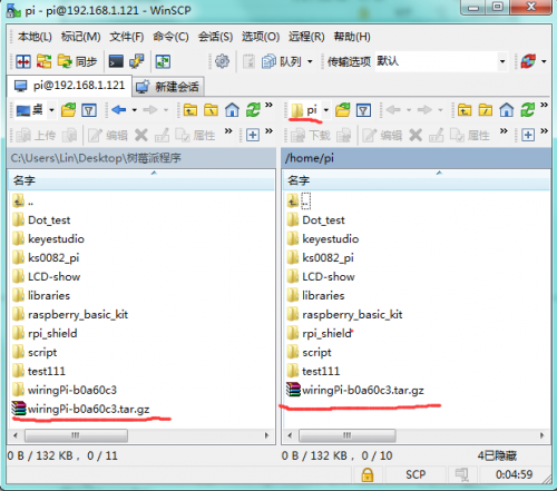
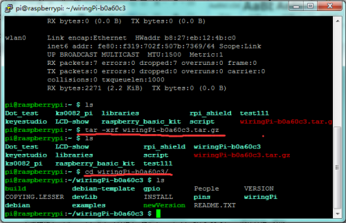
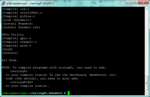
b. In the terminal input cd/home/pi to enter pi folder; execute tar-xzf wiringPi-b0a60c3.tar.gz to unzip the file, getting wiringPi-b0a60c3 folder; in the terminal input cd wiringPi-b0a60c3 command, execute ./build to install wiringpi. The window interface below shows the successful installation:
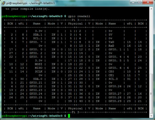
c. To see whether the wiringpi installation is successful, in the terminal execute gpio readall command.
Pop up the below window interface means installation successfully.
Learning Courses
Lesson 1: Hello World
1. Introduction
Since it is the first contact with Raspberry Pi, you just need a raspberry motherboard without other auxiliary components to display "Hello World!"
2. Hardware Required
- USB Cable * 1
- Raspberry Motherboard * 1
3. Programming
a. In the terminal input cd / home / pi and mkdir lesson to build lesson folder.
b. Use winSCP to put Lesson1_Hello_world into the lesson folder of raspberry system.
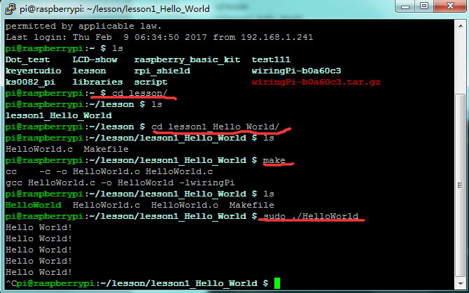
c. In the terminal execute cd lesson and cd lesson1_Hello_World to enter the folder.
d. In the terminal execute make, generating a HelloWorld executable file in the folder.
e. In the terminal execute sudo. / HelloWorld to run the file, the terminal will print Hello World! as the figure shown below.
f. Ctrl + c exits the processing program.
4. Sample Code
#include <wiringPi.h>
#include <stdio.h>

int main()

{
  wiringPiSetup();
//      printf("Hello World!\n");

 for(;;)
 {
 printf("Hello World!\n");
  delay(1000);

 }
  }
5. Special Instruction
lesson1_Hello_World folder has a Makefile file. Code as below:
HelloWorld:HelloWorld.o
gcc HelloWorld.c -o HelloWorld -lwiringPi
Makefile rule:
Target(target): Prerequisite(prerequiries)...
<tab> Command(command)
Target is usually the name of the file to be generated; Prerequiries is the material to generate the target; <tab> Command is a command to execute a target.
When executing the make command in the folder, the system's compiler will generate the executable HelloWorld file according to the instructions in the Malefile file. Executing HelloWorld file, more Makefile knowledge please refer to the relevant information.
Lesson 2: LED Blinking
1. Introduction
LED small light experiment is one of the more basic experiments. In this lesson, we will use I/O port of Raspberry Pi to simply control red LED blinking.
2. Hardware Required
- Red LED *1
- 220ΩResistor*1
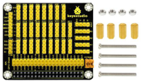
- RPI GPIO Shield*1
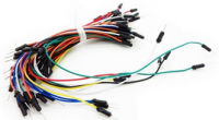
- 40 Pin Colorful Jumper Wires*1
- Breadboard*1
- USB Cable*1
- Raspberry Motherboard*1
- Jumper Wires*Several
4. Programming
a. Use winSCP to put the lesson2_LED_Blinking into the lesson folder of raspberry system.
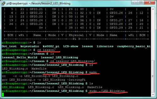
b. In the terminal input cd lesson2_LED_Blinking to enter the folder.
c. In the terminal execute make, generating an LED_Blinking executable file inside the folder.
d. Wiring as the above diagram, then enter the lesson2_LED_Blinking folder, execute sudo ./LED_Blinking on the terminal, and you can see the LED blinking effect.
e. Ctrl + c can exit the processing program.
5. Sample Code
#include <wiringPi.h>
int main()
{
  wiringPiSetup();

  {
        pinMode(1,OUTPUT);
  }

  while(1)
  {
        digitalWrite(1,HIGH);
        delay(500);
        digitalWrite(1,LOW);
        delay(500);
  }

}
Lesson 3: Breathing LED
1. Introduction
In the last lesson, we have controlled the LED light’s on and off by controlling the I/O port of Raspberry Pi to output high and low levels.
This time we come to control LED light’s brightness, and finally make the effect of breathing light.
2. Hardware Required
- Red LED *1
- 220Ω Resistor*1
- RPI GPIO Shield*1
- 40 Pin Colorful Jumper Wires*1
- Breadboard*1
- USB Cable*1
- Raspberry Motherboard*1
- Jumper Wires*Several
4. Programming
a. Use winSCP to put the lesson3_Breathing_LED into the lesson folder of raspberry system.
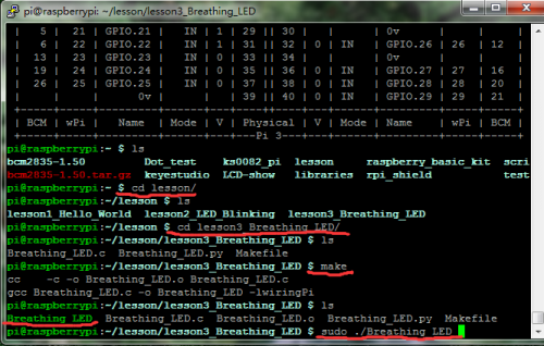
b. In the terminal input cd lesson3_Breathing_LED to enter the folder.
c. In the terminal execute make, to generate a Breathing_LED executable file inside the folder.
d. Wiring as the above diagram, then enter the lesson3_Breathing_LED folder, execute sudo ./Breathing_LED at the terminal.
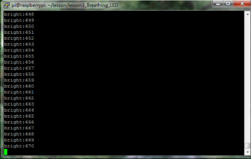
It can achieve the effect of breathing light, and display the corresponding data in the terminal.
e. Ctrl + c can exit the processing program.
5. Sample Code
 #include <stdio.h>
 #include <stdlib.h>
 #include <stdint.h>
 #include <wiringPi.h>
 #define LED 1

int main(void)
{
   int bright;
    printf("Raspberry Pi wiringPi PWM test program\n");
    if (wiringPiSetup() == -1)
     {
        printf("GPIO setup error!\n");
         exit(1);
    }
    pinMode(LED,PWM_OUTPUT);
     while(1)
    {
     for (bright = 0; bright < 1024; ++bright)
         {
            pwmWrite(LED,bright);
            printf("bright:%d\n",bright);
             delay(3);
        }
    for (bright = 1023; bright >= 0; --bright)
        {
             pwmWrite(LED,bright);
             printf("bright:%d\n",bright);
             delay(3);
         }
       }
     return 0;
 }
Lesson 4: Traffic Light
1. Introduction
This lesson is expanded on the basis of lesson 2. We are going to control three LED lights’ on and off by controlling three I/O ports of Raspberry Pi, so as to simulate the traffic light phenomenon.
2. Hardware Required
- LED - Red *1
- LED - Blue*1
- LED - Yellow*1
- 220Ω Resistor*3
- RPI GPIO Shield*1
- Breadboard*1
- 40 Pin Colorful Jumper Wires*1
- USB Cable*1
- Raspberry Motherboard*1
- Jumper Wires*Several
4. Programming
a. Use winSCP to put the lesson4_Traffic_Light into the lesson folder of raspberry system.
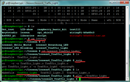
b. In the terminal input cd lesson4_Traffic_Light to enter the folder.
c. In the terminal execute make ,to generate a Traffic_Light executable file inside the folder.
d. Wiring as the above diagram, then enter the lesson4_Traffic_Light folder, execute sudo ./Traffic_Light at the terminal. It can achieve the effect of traffic light.
e. Ctrl + c can exit the processing program.
5. Sample Code
#include <wiringPi.h>
int main()
{
  wiringPiSetup();
  char i;
  char j;
  for(i=1;i<4;i++)
  {
        pinMode(i,OUTPUT);
  }
  while(1)
  {
   digitalWrite(1, HIGH);//// turn on blue LED
   delay(5000);// wait 5 seconds
   digitalWrite(1, LOW); // turn off blue LED
   for(j=0;j<3;j++) // blinks for 3 times
   {
   delay(500);// wait 0.5 second
   digitalWrite(2, HIGH);// turn on yellow LED
   delay(500);// wait 0.5 second
   digitalWrite(2, LOW);// turn off yellow LED
   }
   delay(500);// wait 0.5 second
   digitalWrite(3, HIGH);// turn on red LED
   delay(5000);// wait 5 second
   digitalWrite(3, LOW);// turn off red LED
   }
}
Lesson 5: LED Chasing Effect
1. Introduction
This lesson is expanded on the basis of lesson 2. We are going to control three LED lights’ on and off by controlling three I/O ports of Raspberry Pi, so as to achieve the flowing water light phenomenon.
2. Hardware Required
- Red LED*3
- 220Ω Resistor*3
- RPI GPIO Shield*1
- Breadboard*1
- 40 Pin Colorful Jumper Wires*1
- USB Cable*1
- Raspberry Motherboard*1
- Jumper Wires*Several
4. Programming
a. Use winSCP to put the lesson5_LED_Chasing_Effect into the lesson folder of raspberry system.
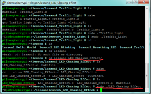
b. In the terminal input cd lesson5_LED_Chasing_Effect to enter the folder.
c. In the terminal execute make ,to generate an LED_Chasing_Effect executable file inside the folder.
d. Wiring as the above diagram, then enter the lesson5_LED_Chasing_Effect folder, execute sudo ./LED_Chasing_Effect at the terminal. It can achieve the effect of flowing water light.
e. Ctrl + c can exit the processing program.
5. Sample Code
#include <wiringPi.h>
int main()
{
  wiringPiSetup();
  char i;
  for(i=1;i<4;i++)
  {
    pinMode(i,OUTPUT);
  }

  while(1)
  {
    for (i=1;i<4;i ++)
   {
    digitalWrite(i, LOW);// set I/O pins as “low”
     delay(200);        // delay
   }
   for (i=1;i<4;i ++)
   {
     digitalWrite(i, HIGH);// set I/O pins as “high”
     delay(200);       // delay
   }
  }
}
Lesson 6: Button-controlled LED
1. Introduction
I/O port means the INPUT interface and OUTPUT interface. In the above courses we only used the output function of Raspberry Pi I/O port, so this time we will use its I/O port input function. In this lesson, we use a button component to control the LED’s on and off.
2. Hardware Required
- Red LED*1
- 220Ω Resistor*1
- Large Button Switch *1
- 10KΩ Resistor*1
- RPI GPIO Shield*1
- 40 Pin Colorful Jumper Wires*1
- Breadboard*1
- USB Cable*1
- Raspberry Motherboard*1
- Jumper Wires*Several
4. Programming
a. Use winSCP to put the lesson6_Button_controlled_LED into the lesson folder of raspberry system.
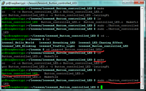
b. In the terminal input cd lesson6_Button_controlled_LED to enter the folder.
c. In the terminal execute make, to generate a Button_controlled_LED executable file inside the folder.
d. Wiring as the above diagram, then enter the lesson6_Button_controlled_LED folder, execute sudo ./Button_controlled_LED at the terminal. It can achieve the effect of button controlled LED.
e. Ctrl + c can exit the processing program.
5. Sample Code
#include <wiringPi.h>
int main()
{
  wiringPiSetup();
  char val;
  {
    pinMode(1,INPUT);
    pinMode(2,OUTPUT);
  }
  while(1)
  {
   val=digitalRead(1);
   if(val==1)//check if the button is pressed, if yes, turn on the LED
   digitalWrite(2,LOW);
   else
   digitalWrite(2,HIGH);
  }
}
Lesson 7: Passive Buzzer
1. Introduction
Using Raspberry Pi can finish many interactive works. The most common seen and used is the sound and light show. We have used LED in the previous experiment, so this experiment will let the circuit make sound. We will use the passive buzzer and its ideal working signal is square wave. In the experiment, using Raspberry Pi’s I/O port outputs high and low levels to simulate square wave, thus controlling the passive buzzer ringing.
2. Hardware Required
- Passive Buzzer*1
- RPI GPIO Shield*1
- 40 Pin Colorful Jumper Wires*1
- Breadboard*1
- USB Cable*1
- Raspberry Motherboard*1
- Jumper Wires*Several
4. Programming
a. Use winSCP to put the lesson7_Passive_Buzzer into the lesson folder of raspberry system.
b. In the terminal input cd lesson7_Passive_Buzzer to enter the folder.
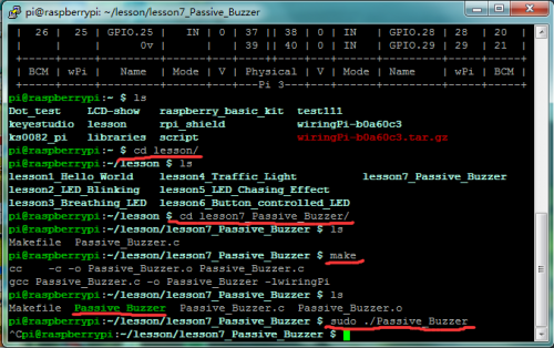
c. In the terminal execute make ,to generate a Passive_Buzzer executable file inside the folder.
d. Wiring as the above diagram, then enter the lesson7_Passive_Buzzer folder, execute sudo ./Passive_Buzzer at the terminal. It can achieve the effect of passive buzzer ringing.
e. Ctrl + c can exit the processing program.
5. Sample Code
#include <wiringPi.h>
int main()
{
  wiringPiSetup();
  char i;
  char j;

  {
    pinMode(1,OUTPUT);
  }
  while(1)
   {
    for(i=0;i<80;i++)// output a frequency sound
   { digitalWrite(1,HIGH);// sound
     delay(1);//delay1ms
     digitalWrite(1,LOW);//not sound
     delay(1);//ms delay
    }
   for(j=0;j<100;j++)// output a frequency sound
    { digitalWrite(1,HIGH);// sound
      delay(2);
      digitalWrite(1,LOW);//not sound
      delay(2);//2ms delay
     }
   }
  }
Lesson 8: Active Buzzer
1. Introduction
In the last lesson, we have finished a passive buzzer ringing experiment. This time, we will make an active buzzer sound test. Relative to the passive buzzer, active buzzer can automatically make sounds only inputting a high level because it has an own oscillator source. In the experiment, we simply let the buzzer ring for one second and stop for one second, repeating alternately.
2. Hardware Required
- Active Buzzer *1
- RPI GPIO Shield*1
- 40 Pin Colorful Jumper Wires*1
- Breadboard*1
- USB Cable*1
- Raspberry Motherboard*1
- Jumper Wires*Several
3. Connection Diagram
4. Programming
a. Use winSCP to put the lesson8_Active_Buzzer into the lesson folder of raspberry system.
b. In the terminal input cd lesson8_Active_Buzzer to enter the folder.
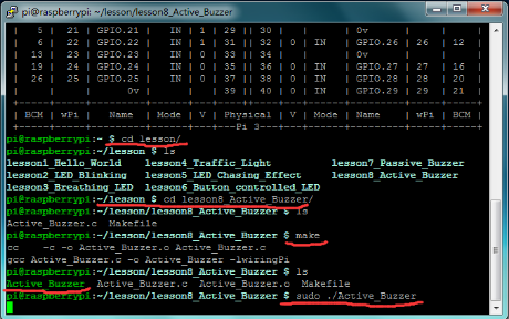
c. In the terminal execute make, to generate an Active_Buzzer executable file inside the folder.
d. Wiring as the above diagram, then enter the lesson8_Active_Buzzer folder, execute sudo ./Active_Buzzer at the terminal. The active buzzer rings for one second and stops for one second, repeating alternately.
e. Ctrl + c can exit the processing program.
5. Sample Code
#include <wiringPi.h>
int main()
{
  wiringPiSetup();

  {
        pinMode(1,OUTPUT);
  }

  while(1)
  {
        digitalWrite(1,HIGH);
        delay(1000);
        digitalWrite(1,LOW);
        delay(1000);
  }

}
Lesson 9: Responder
1. Introduction
In this experiment, we make a further learning on the basis of lesson 6. We use four buttons to control three LEDs, making a responder.
2. Hardware Required
- LED - Red *1
- LED - Blue*1
- LED - Yellow*1
- 220Ω Resistor*3
- Large Button Switch *4
- 10KΩ Resistor*4
- RPI GPIO Shield*1
- 40 Pin Colorful Jumper Wire*1
- Breadboard*1
- USB Cable*1
- Raspberry Motherboard*1
- Jumper Wires*Several
4. Programming
a. Use winSCP to put the lesson9_Responder into the lesson folder of raspberry system.
b. In the terminal input cd lesson9_Responder to enter the folder.
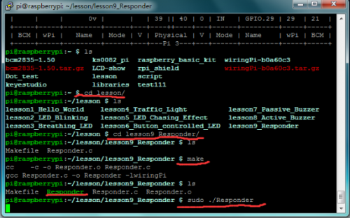
c. In the terminal execute make, to generate a Responder executable file inside the folder.
d. Wiring as the above diagram, then enter the lesson9_Responder folder, execute sudo ./Responder at the terminal. Press the corresponding button to control the LED, so it is equivalent to a responder.
e. Ctrl + c can exit the processing program.
5. Sample Code
#include <wiringPi.h>
int redled=25;     // set red LED as “output”
int yellowled=24;  // set yellow LED as “output”
int blueled=23;   // set blue LED as “output”
int redpin=4;     // initialize pin for red button
int yellowpin=5;  // initialize pin for yellow button
int bluepin=6;   // initialize pin for blue button
int restpin=1;   // initialize pin for reset button
int red;
int yellow;
int blue;
void clear_led()// all LED off
{
 digitalWrite(redled,LOW);
 digitalWrite(blueled,LOW);
 digitalWrite(yellowled,LOW);
}
void RED_YES()// execute the code until red light is on; end cycle when reset button is pressed
{
 while(digitalRead(restpin)==1)
 {
 digitalWrite(redled,HIGH);
 digitalWrite(blueled,LOW);
 digitalWrite(yellowled,LOW);
 }
 clear_led();
 }
 void YELLOW_YES()// execute the code until yellow light is on; end cycle when reset button is pressed
 {
  while(digitalRead(restpin)==1)
 {
 digitalWrite(redled,LOW);
 digitalWrite(blueled,LOW);
 digitalWrite(yellowled,HIGH);
 }
 clear_led();
  }
 void BLUE_YES()// execute the code until green light is on; end cycle when reset button is pressed
 {
  while(digitalRead(restpin)==1)
  {
  digitalWrite(redled,LOW);
  digitalWrite(blueled,HIGH);
  digitalWrite(yellowled,LOW);
  }
  clear_led();
 }

int main()
{
  wiringPiSetup();

  {
   pinMode(redled,OUTPUT);
   pinMode(yellowled,OUTPUT);
   pinMode(blueled,OUTPUT);
   pinMode(redpin,INPUT);
   pinMode(yellowpin,INPUT);
   pinMode(bluepin,INPUT);
  }

  while(1)
  {
   red=digitalRead(redpin);
   yellow=digitalRead(yellowpin);
   blue=digitalRead(bluepin);
   if(red==LOW)RED_YES();
   if(yellow==LOW)YELLOW_YES();
   if(blue==LOW)BLUE_YES();
  }
}
Lesson 10: Flame Sensor
1. Introduction
We have done a button controlled light in experiment 6, so this time we do a flame alarm test using flame sensor. The flame sensor is specially used for robots to search the fire source, which is very sensitive to flame.
This flame sensor makes use of the high sensibility of infrared towards flame, using special IR receiver to detect the flame and then converting the brightness of flame into high or low level signal. In the experiment, we input the high or low level signal converted by the brightness of flame to the control board of raspberry pi, and then to control the buzzer’s ring.
2. Hardware Required
- Active Buzzer *1
- Flame Sensor *1
- 10KΩ Resistor*1
- RPI GPIO Shield*1
- 40 Pin Colorful Jumper Wires*1
- Breadboard*1
- USB Cable*1
- Raspberry Motherboard*1
- Jumper Wire*Several
4. Programming
a. Use winSCP to put the lesson10_Flame_Sensor into the lesson folder of raspberry system.
b. In the terminal input cd lesson10_Flame_Sensor to enter the folder.
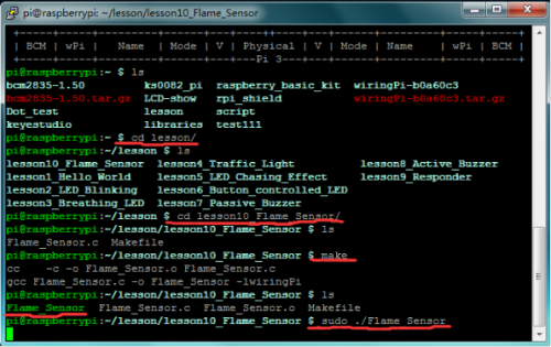
c. In the terminal execute make, to generate a Flame_Sensor executable file inside the folder.
d. Wiring as the above diagram, then enter the lesson10_Flame_Sensor folder, execute sudo ./Flame_Sensor at the terminal. It can achieve the effect of flame alarm.
e. Ctrl + c can exit the processing program.
5. Sample Code
#include <wiringPi.h>
int main()
{
  wiringPiSetup();
  char val;
  {
    pinMode(1,INPUT);
    pinMode(2,OUTPUT);
  }

  while(1)
  {
   val=digitalRead(1);
   if(val==1)
   digitalWrite(2,LOW);
   else
   digitalWrite(2,HIGH);
  }
}
Lesson 11: Ball Tilt Sensor
1. Introduction
Ball tilt sensor uses the same theory as tilt switch, in which has a little metal ball. When it keeps upright, the metal ball touches two ends of power supply wire; while placed upside down, it is disconnected, so that the upright and inverted placement produce different signals. We use button to control LED status in experiment 6, but this time we use the ball tilt switch to control the LED’s on and off.
2. Hardware Required
- LED - Red *1
- 220Ω Resistor*1
- Ball Tilt Sensor*1
- 10KΩ Resistor*1
- RPI GPIO Shield*1
- 40 Pin Colorful Jumper Wires*1
- Breadboard*1
- USB Cable*1
- Raspberry Motherboard*1
- Jumper Wire*Several
4. Programming
a. Use winSCP to put the lesson11_Ball_Tilt_Sensor into the lesson folder of raspberry system.
b. In the terminal input cd lesson11_Ball_Tilt_Sensor to enter the folder.
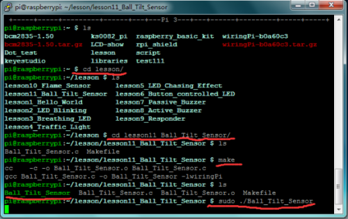
c. In the terminal execute make, to generate a Ball_Tilt_Sensor executable file inside the folder.
d. Wiring as the above diagram, then enter the lesson11_Ball_Tilt_Sensor folder, execute sudo ./Ball_Tilt_Sensor at the terminal. It can achieve the effect of ball tilt switch controlled LED.
e. Ctrl + c can exit the processing program.
5. Sample Code
#include <wiringPi.h>
int main()
{
  wiringPiSetup();
  char val;
  {
    pinMode(1,INPUT);
    pinMode(2,OUTPUT);
  }

  while(1)
  {
   val=digitalRead(1);
   if(val==1)
   digitalWrite(2,LOW);
   else
   digitalWrite(2,HIGH);
  }
}
Lesson 12: IR Remote Control
1. Introduction
The general IR remote control system is divided into two parts: transmitter and receiver. In this experiment, the transmitting part is remote control and the receiving part is IR receiver VS1838B. IR receiver VS1838B is a component integrated with receiving, amplification and demodulation, where its internal IC has been demodulated, and outputs the digital signal.
In this experiment, when the program is compiled and executed, press down the button of remote control, the terminal will display the value of button.
2. Hardware Required
- IR Receiver *1
- IR Remote Control*1
- RPI GPIO Shield*1
- 40 Pin Colorful Jumper Wires*1
- Breadboard*1
- USB Cable*1
- Raspberry Motherboard*1
- Jumper Wire*Several
4. Programming
a. Use winSCP to put the lesson12_IR_Remote_Control into the lesson folder of raspberry system.
b. In the terminal input cd lesson12_IR_Remote_Control to enter the folder.
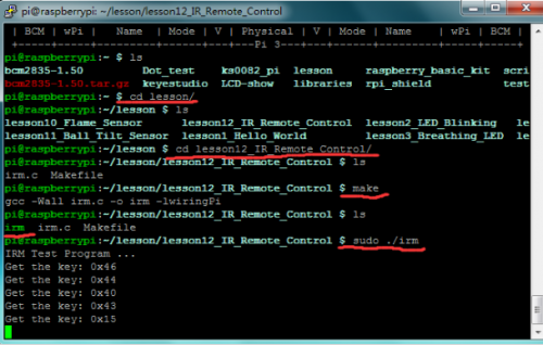
c. In the terminal execute make, to generate an irm executable file inside the folder.
d. Wiring as the above diagram, then enter the lesson12_IR_Remote_Control folder, execute sudo ./irm at the terminal.
When we press down the button of remote control assigned with the IR receiver module, the terminal will display the value of button.
e. Ctrl + c can exit the processing program.
5. Sample Code
#include <wiringPi.h>
#include <stdio.h>
#define PIN 1
#define IO digitalRead(PIN)
unsigned char i,idx,cnt;
unsigned char count;
unsigned char data[4];

int main()
{
    if (wiringPiSetup() < 0)return 1;
    pinMode(PIN, INPUT);
    pullUpDnControl(PIN, PUD_UP);
	printf("IRM Test Program ... \n");

	while (1)
	{
		if(IO == 0)
		{
			count = 0;
			while(IO == 0 && count++ < 200)   //9ms
		    	delayMicroseconds(60);

			count = 0;
			while(IO == 1 && count++ < 80)	  //4.5ms
		    	delayMicroseconds(60);

			idx = 0;
			cnt = 0;
			data[0]=0;
			data[1]=0;
			data[2]=0;
			data[3]=0;
			for(i =0;i<32;i++)
			{
				count = 0;
				while(IO == 0 && count++ < 15)  //0.56ms
		    		delayMicroseconds(60);

				count = 0;
				while(IO == 1 && count++ < 40)  //0: 0.56ms; 1: 1.69ms
		    		delayMicroseconds(60);

				if (count > 25)data[idx] |= (1<<cnt);
				if(cnt == 7)
				{
					cnt = 0;
					idx++;
				}
				else cnt++;
			}

			if(data[0]+data[1] == 0xFF && data[2]+data[3]==0xFF)	//check
				printf("Get the key: 0x%02x\n",data[2]);
		}
	}
}
Lesson 13: 1-digit LED Segment Display
1. Introduction
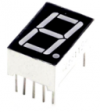
LED segment display is a kind of semiconductor light emitting device whose basic unit is a light emitting diode. LED segment display is divided into 7-seg display and 8-seg display according to the number of segment. Compared to 7-seg display, 8-seg display has more than one light-emitting diode unit (more than a decimal point display).
In this experiment, we will use 8-seg LED display. There are seven segments of LED display to display the number, and the balance segment shows the decimal point. As long as the corresponding segment is lighted up, the segment LED display will show its number. So in this experiment, we will make 1-digit LED display show several numbers.
2. Hardware Required
- 1-digit LED*1
- 220Ω Resistor*8
- RPI GPIO Shield*1
- 40 Pin Colorful Jumper Wires*1
- Breadboard*1
- USB Cable*1
- Raspberry Motherboard*1
- Jumper Wire*Several
4. Programming
a. Use winSCP to put the lesson13_1_digit_LED_Segment_Display into the lesson folder of raspberry system.
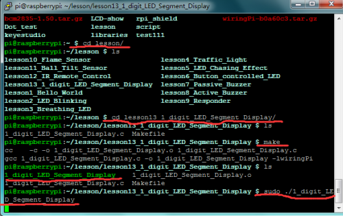
b. In the terminal input cd lesson13_1_digit_LED_Segment_Display to enter the folder.
c. In the terminal execute make, to generate a 1_digit_LED_Segment_Display executable file inside the folder.
d. Wiring as the above diagram, then enter the lesson13_1_digit_LED_Segment_Display folder, execute sudo ./1_digit_LED_Segment_Display at the terminal, 1-digit LED segment display will successively show the number from 0 to 9.
e. Ctrl + c can exit the processing program.
5. Sample Code
#include <wiringPi.h>
int a=27;//GPIO16
int b=26;//GPIO12
int c=23;//GPIO13
int  int e=25;//GPIO26
int f=28;// GPIO20
int g=29;//GPIO21
int dp=22;//GPIO6
int i;
void digital_0()//0
{
digitalWrite(a,HIGH);
digitalWrite(b,HIGH);
digitalWrite(c,HIGH);
digitalWrite(d,HIGH);
digitalWrite(e,HIGH);
digitalWrite(f,HIGH);
digitalWrite(g,LOW);
digitalWrite(dp,LOW);
}
void digital_1()//1
{
digitalWrite(a,LOW);
digitalWrite(b,HIGH);
digitalWrite(c,HIGH);
digitalWrite(d,LOW);
digitalWrite(e,LOW);
digitalWrite(f,LOW);
digitalWrite(g,LOW);
digitalWrite(dp,LOW);
}
void digital_2()//2
{
digitalWrite(a,HIGH);
digitalWrite(b,HIGH);
digitalWrite(c,LOW);
digitalWrite(d,HIGH);
digitalWrite(e,HIGH);
digitalWrite(f,LOW);
digitalWrite(g,HIGH);
digitalWrite(dp,LOW);
}
void digital_3()//3
{
digitalWrite(a,HIGH);
digitalWrite(b,HIGH);
digitalWrite(c,HIGH);
digitalWrite(d,HIGH);
digitalWrite(e,LOW);
digitalWrite(f,LOW);
digitalWrite(g,HIGH);
digitalWrite(dp,LOW);
}
void digital_4()//4
{
digitalWrite(a,LOW);
digitalWrite(b,HIGH);
digitalWrite(c,HIGH);
digitalWrite(d,LOW);
digitalWrite(e,LOW);
digitalWrite(f,HIGH);
digitalWrite(g,HIGH);
digitalWrite(dp,LOW);
}
void digital_5()//5
{
digitalWrite(a,HIGH);
digitalWrite(b,LOW);
digitalWrite(c,HIGH);
digitalWrite(d,HIGH);
digitalWrite(e,LOW);
digitalWrite(f,HIGH);
digitalWrite(g,HIGH);
digitalWrite(dp,LOW);
digitalWrite(e,LOW);
}
void digital_6()//6
{
digitalWrite(a,HIGH);
digitalWrite(b,LOW);
digitalWrite(c,HIGH);
digitalWrite(d,HIGH);
digitalWrite(e,HIGH);
digitalWrite(f,HIGH);
digitalWrite(g,HIGH);
digitalWrite(dp,LOW);
}
void digital_7()//7
{
digitalWrite(a,HIGH);
digitalWrite(b,HIGH);
digitalWrite(c,HIGH);
digitalWrite(d,LOW);
digitalWrite(e,LOW);
digitalWrite(f,LOW);
digitalWrite(g,LOW);
digitalWrite(dp,LOW);
}
void digital_8()//8
{
digitalWrite(a,HIGH);
digitalWrite(b,HIGH);
digitalWrite(c,HIGH);
digitalWrite(d,HIGH);
digitalWrite(e,HIGH);
digitalWrite(f,HIGH);
digitalWrite(g,HIGH);
digitalWrite(dp,LOW);
}
void digital_9()//9
{
digitalWrite(a,HIGH);
digitalWrite(b,HIGH);
digitalWrite(c,HIGH);
digitalWrite(d,HIGH);
digitalWrite(e,LOW);
digitalWrite(f,HIGH);
digitalWrite(g,HIGH);
digitalWrite(dp,LOW);
}
int main()
{
 wiringPiSetup();
{
for(i=22;i<=29;i++)
pinMode(i,OUTPUT);
 }
 while(1)
  {
  digital_0();//0
  delay(1000);
  digital_1();//1
  delay(1000);
  digital_2();//2
  delay(1000);
  digital_3();//3
  delay(1000);
  digital_4();//4
  delay(1000);
  digital_5();//5
  delay(1000);
  digital_6();//6
  delay(1000);
  digital_7();//7
  delay(1000);
  digital_8();//8
  delay(1000);
  digital_9();//9
  delay(1000);
  }
}
Lesson 14: 74HC595
1. Introduction
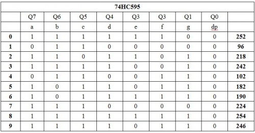
In the previous project, we use raspberry pi to control 1-digit LED segment display, occupying 8 GPIO ports. While the GPIO port of raspberry pi is limited, in order to save the GPIO port, this time we will use 74HC595 chip to control 1-digit LED segment display only using 3 GPIO ports.
The wiring and setting method please refer to the following table
2. Hardware Required
- 74HC595N*1
- 1-digit LED Segment Display *1
- 220Ω Resistor*8
- RPI GPIO Shield*1
- 40 Pin Colorful Jumper Wires*1
- Breadboard*1
- USB Cable*1
- Raspberry Motherboard*1
- Jumper Wire*Several
4. Programming
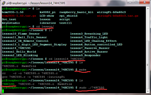
a. Use winSCP to put the lesson14_74HC595 into the lesson folder of raspberry system.
b. In the terminal input cd lesson14_74HC595 to enter the folder.
c. In the terminal execute make, to generate a 74HC595 executable file inside the folder.
d. Wiring as the above diagram, then enter the lesson14_74HC595 folder, execute sudo ./74HC595 at the terminal.
1-digit LED segment display will successively show the number from 0 to 9.
e. Ctrl + c can exit the processing program.
5. Sample Code
#include <wiringPi.h>
#include <wiringShift.h>
int dataPin = 23; //define three pins
int latchPin = 24;
int clockPin = 25;
int a[10]={
    252,96,218,242,102,182,190,224,254,246};
int x;
int main()
{
  wiringPiSetup();

  {
  pinMode(latchPin,OUTPUT);
  pinMode(clockPin,OUTPUT);
  pinMode(dataPin,OUTPUT); //three pins as output
  }

  while(1)
  {
  for(x=0; x<10 ;x++ )        //calculate counting function
  {
    digitalWrite(latchPin,LOW);
    shiftOut(dataPin,clockPin,MSBFIRST,a[x]);     //display array a[x]
    digitalWrite(latchPin,HIGH);
    delay(1000);
  }
  }
}
Lesson 15: 4-digit LED Segment Display
1. Introduction
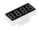
We have directly used raspberry pi to drive a 1-digit LED segment display, and this time we also use it to drive a common cathode 4-digit LED segment display. But it is necessary to use current-limiting resistor, and there are two connection methods for it.
One is connected to d1-d4 common cathode, in total 4 pieces, with the advantages of using fewer resistors but displaying different brightness for different number. Another way is connected to other 8 pins, displaying consistent brightness but requiring more resistors. This test will use 8 220Ω resistors.
2. Hardware Required
- 4-digit LED*1
- 220Ω Resistor* 8
- RPI GPIO Shield* 1
- 40 Pin Colorful Jumper Wires* 1
- USB Cable*1
- Raspberry Motherboard*1
- Breadboard*1
- Jumper Wire* Several
4. Programming
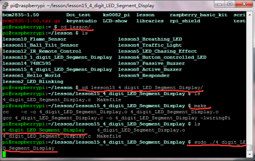
a. Use winSCP to put the lesson15_4_digit_LED_Segment_Display into the lesson folder of raspberry system.
b. In the terminal input cd lesson15_4_digit_LED_Segment_Display to enter the folder.
c. In the terminal execute make, to generate a 4_digit_LED_Segment_Display executable file inside the folder.
d. Wiring as the above diagram, then enter the lesson15_4_digit_LED_Segment_Display folder, execute sudo ./4_digit_LED_Segment_Display at the terminal.
4-digit LED segment display will first show “0000”, displaying jump, and the segment display value will add one if it jumps at a time. When the display value is greater than “9999”, it will return to “0000” once again, circularly displaying.
e. Ctrl + c can exit the processing program.
5. Sample Code
#include <wiringPi.h>
int a = 28;// GPIO20
int b = 5; // GPIO24
int c = 22;// GPIO6
int d = 24;// GPIO19
int e = 25;// GPIO26
int f = 27;// GPIO16
int g = 21;// GPIO5
int dp = 23;// GPIO13

int d4 = 3;// GPIO22
int d3 = 6;// GPIO25
int d2 = 26;// GPIO12
int d1 = 29;// GPIO21
// set variable
long n = 1230;
int x = 100;
int del = 55;    // fine adjustment for clock
void WeiXuan(unsigned char n)//
{
  switch (n)
  {
    case 1:
      digitalWrite(d1, LOW);
      digitalWrite(d2, HIGH);
      digitalWrite(d3, HIGH);
      digitalWrite(d4, HIGH);
      break;
    case 2:
      digitalWrite(d1, HIGH);
      digitalWrite(d2, LOW);
      digitalWrite(d3, HIGH);
      digitalWrite(d4, HIGH);
      break;
    case 3:
      digitalWrite(d1, HIGH);
      digitalWrite(d2, HIGH);
      digitalWrite(d3, LOW);
      digitalWrite(d4, HIGH);
      break;
    case 4:
      digitalWrite(d1, HIGH);
      digitalWrite(d2, HIGH);
      digitalWrite(d3, HIGH);
      digitalWrite(d4, LOW);
      break;
    default :
      digitalWrite(d1, HIGH);
      digitalWrite(d2, HIGH);
      digitalWrite(d3, HIGH);
      digitalWrite(d4, HIGH);
      break;
  }
}
void Num_0()
{
  digitalWrite(a, HIGH);
  digitalWrite(b, HIGH);
  digitalWrite(c, HIGH);
  digitalWrite(d, HIGH);
  digitalWrite(e, HIGH);
  digitalWrite(f, HIGH);
  digitalWrite(g, LOW);
  digitalWrite(dp, LOW);
}
void Num_1()
{
  digitalWrite(a, LOW);
  digitalWrite(b, HIGH);
  digitalWrite(c, HIGH);
  digitalWrite(d, LOW);
  digitalWrite(e, LOW);
  digitalWrite(f, LOW);
  digitalWrite(g, LOW);
  digitalWrite(dp, LOW);
}
void Num_2()
{
  digitalWrite(a, HIGH);
  digitalWrite(b, HIGH);
  digitalWrite(c, LOW);
  digitalWrite(d, HIGH);
  digitalWrite(e, HIGH);
  digitalWrite(f, LOW);
  digitalWrite(g, HIGH);
  digitalWrite(dp, LOW);
}
void Num_3()
{
  digitalWrite(a, HIGH);
  digitalWrite(b, HIGH);
  digitalWrite(c, HIGH);
  digitalWrite(d, HIGH);
  digitalWrite(e, LOW);
  digitalWrite(f, LOW);
  digitalWrite(g, HIGH);
  digitalWrite(dp, LOW);
}
void Num_4()
{
  digitalWrite(a, LOW);
  digitalWrite(b, HIGH);
  digitalWrite(c, HIGH);
  digitalWrite(d, LOW);
  digitalWrite(e, LOW);
  digitalWrite(f, HIGH);
  digitalWrite(g, HIGH);
  digitalWrite(dp, LOW);
}
void Num_5()
{
  digitalWrite(a, HIGH);
  digitalWrite(b, LOW);
  digitalWrite(c, HIGH);
  digitalWrite(d, HIGH);
  digitalWrite(e, LOW);
  digitalWrite(f, HIGH);
  digitalWrite(g, HIGH);
  digitalWrite(dp, LOW);
}
void Num_6()
{
  digitalWrite(a, HIGH);
  digitalWrite(b, LOW);
  digitalWrite(c, HIGH);
  digitalWrite(d, HIGH);
  digitalWrite(e, HIGH);
  digitalWrite(f, HIGH);
  digitalWrite(g, HIGH);
  digitalWrite(dp, LOW);
}
void Num_7()
{
  digitalWrite(a, HIGH);
  digitalWrite(b, HIGH);
  digitalWrite(c, HIGH);
  digitalWrite(d, LOW);
  digitalWrite(e, LOW);
  digitalWrite(f, LOW);
  digitalWrite(g, LOW);
  digitalWrite(dp, LOW);
}
void Num_8()
{
  digitalWrite(a, HIGH);
  digitalWrite(b, HIGH);
  digitalWrite(c, HIGH);
  digitalWrite(d, HIGH);
  digitalWrite(e, HIGH);
  digitalWrite(f, HIGH);
  digitalWrite(g, HIGH);
  digitalWrite(dp, LOW);
}
void Num_9()
{
  digitalWrite(a, HIGH);
  digitalWrite(b, HIGH);
  digitalWrite(c, HIGH);
  digitalWrite(d, HIGH);
  digitalWrite(e, LOW);
  digitalWrite(f, HIGH);
  digitalWrite(g, HIGH);
  digitalWrite(dp, LOW);
}
void Clear()    // clear the screen
{
  digitalWrite(a, LOW);
  digitalWrite(b, LOW);
  digitalWrite(c, LOW);
  digitalWrite(d, LOW);
  digitalWrite(e, LOW);
  digitalWrite(f, LOW);
  digitalWrite(g, LOW);
  digitalWrite(dp, LOW);
}

void pickNumber(unsigned char n)// select number
{
  switch (n)
  {
    case 0: Num_0();

      break;
    case 1: Num_1();
      break;
    case 2: Num_2();
      break;
    case 3: Num_3();
      break;
    case 4: Num_4();
      break;
    case 5: Num_5();
      break;
    case 6: Num_6();
      break;
    case 7: Num_7();
      break;
    case 8: Num_8();
      break;
    case 9: Num_9();
      break;
    default: Clear();
      break;
  }
}
void Display(unsigned char x, unsigned char Number)//    take x as coordinate and display number
{
  WeiXuan(x);
  pickNumber(Number);
  delay(1);
  Clear() ; // clear the screen
}
int i;
int main()
{
 wiringPiSetup();
{
{
pinMode(3,OUTPUT);
pinMode(5,OUTPUT);
pinMode(6,OUTPUT);
}
for(i=21;i<=29;i++)
{
pinMode(i,OUTPUT);
}
}
 while(1)
  {
  int w=0;
  int s=0;
  int y=0;
  int z=0;
  unsigned long currentMillis = millis();

  while(z>=0)
  {
    while(millis()-currentMillis<100)
     {
      Display(1,w);
      Display(2,s);
      Display(3,y);
      Display(4,z);
     }
    currentMillis = millis();
    z++;
  if (z>9)
  {
   y++;
   z=0;
  }
    if (y>9)
  {
   s++;
   y=0;
  }
    if (s>9)
  {
   w++;
   s=0;
  }
    if (w>9)
  {
   w=0;
   s=0;
   y=0;
   z=0;
  }
  }
 }
}
Lesson 16: LED Matrix Display
1. Introduction
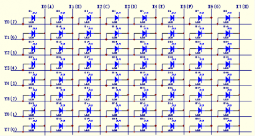
This project, we are going to display various patterns by controlling a 8*8 LED Matrix. Supposed that it is only controlled by raspberry pi, so we just need to control 8-row 8-column in total 16 GPIO ports. Since GPIO port is limited and to save it, this time we use two 74HC595 chips to control 8*8 LED Matrix, one for 8-row, the other for 8-column, only using 3 GPIO ports.
Schematics of 8*8 LED Matrix:
2. Hardware Required
- 8*8 LED Matrix*1
- 220Ω Resistor*8
- RPI GPIO Shield*1
- 40 pin Colorful Jumper Wires*1
- Breadboard*1
- USB Cable*1
- Raspberry Motherboard*1
- Jumper Wire* Several
4. Programming
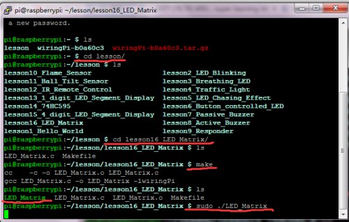
a. Use winSCP to put the lesson16_LED_Matrix into the lesson folder of raspberry system.
b. In the terminal input cd lesson16_LED_Matrix to enter the folder.
c. In the terminal execute make, to generate an LED_Matrix executable file inside the folder.
d. Wiring as the above diagram, then enter the lesson16_LED_Matrix folder, execute sudo ./LED_Matrix at the terminal.
8*8 LED Matrix will show GIF image.
e. Ctrl + c can exit the processing program.
5. Sample Code
#include <wiringPi.h>
int main()
{
  wiringPiSetup();
  char i;
  char j;
  for(i=0;i<8;i++)
  {
    pinMode(i,OUTPUT);
  }
    for(j=21;j<29;j++)
  {
    pinMode(j,OUTPUT);
  }
  while(1)
  {
    for(i=0;i<8;i++)
  {
     digitalWrite(i, HIGH);// set I/O pins as “high”
      delay(200);       // delay
  }
     for(j=21;j<29;j++)
  {
     digitalWrite(j, LOW);// set I/O pins as “low”
  }
    for(i=0;i<8;i++)
  {
     digitalWrite(i, LOW);// set I/O pins as “high”
     delay(200);       // delay
  }
    for(i=0;i<8;i++)
  {
     digitalWrite(i, HIGH);// set I/O pins as “high”
     delay(200);       // delay
  }
     for(j=21;j<29;j++)
  {
     digitalWrite(j,HIGH);// set I/O pins as “high”
     delay(200);       // delay
  }
     for(j=21;j<29;j++)
  {
     digitalWrite(j, LOW);// set I/O pins as “low”
     delay(200);       // delay
  }
    for(i=0;i<8;i++)
  {
     digitalWrite(i, LOW);// set I/O pins as “low”
     delay(200);       // delay
  }
  }
}
Lesson 17: 1602 LCD
1. Introduction
In this lesson, we will use raspberry pi to control a 1602 LCD to display number 0. This time we use 11 GPIO ports and 8-bit connection method.
2. Hardware Required
- 1602 LCD Display *1
- 10KΩ Potentiometer*1
- RPI GPIO Shield*1
- 40 Pin Colorful Jumper Wires*1
- Breadboard*1
- USB Cable*1
- Raspberry Motherboard*1
- Jumper Wire*Several
4. Programming
a. Use winSCP to put the lesson17_1602_LCD into the lesson folder of raspberry system.
b. In the terminal input cd lesson17_1602_LCD to enter the folder.
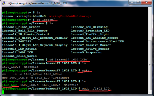
c. In the terminal execute make to generate a 1602_LCD executable file inside the folder.
d. Wiring as the above diagram, then enter the lesson17_1602_LCD folder, execute sudo ./1602_LCD at the terminal.
1602 LED will display the number.
e. Ctrl + c can exit the processing program.
5. Sample Code
#include <wiringPi.h>
int main()
{

//int RS=21,RW=22,EN=23;
//int DB0=3,DB1=4,DB2=5,DB3=6,DB4=7,DB5=8,DB6=9,DB7=10;
int DB0=0,DB1=1,DB2=2,DB3=3,DB4=4,DB5=5,DB6=6,DB7=7;
int RS=21,RW=22,EN=23;
//int i;
int i;

wiringPiSetup();


  //Serial.begin(9600);
      pinMode(RS,OUTPUT);
      pinMode(RW,OUTPUT);
      pinMode(EN,OUTPUT);
      pinMode(DB0,OUTPUT);
      pinMode(DB1,OUTPUT);
      pinMode(DB2,OUTPUT);
      pinMode(DB3,OUTPUT);
      pinMode(DB4,OUTPUT);
      pinMode(DB5,OUTPUT);
      pinMode(DB6,OUTPUT);
      pinMode(DB7,OUTPUT);


  digitalWrite(RS,HIGH);
  digitalWrite(RW,LOW);
  digitalWrite(RS,LOW);
  digitalWrite(EN,LOW);
  delay(1);
   //digitalWrite(DB0,0);
   //digitalWrite(DB1,0);
   digitalWrite(DB2,0);
   digitalWrite(DB3,1);
   digitalWrite(DB4,1);
   digitalWrite(DB5,1);
   digitalWrite(DB6,0);
   digitalWrite(DB7,0);
  digitalWrite(EN,HIGH);

  //Serial.println("zzl");

   delay(1);
   digitalWrite(EN,LOW);
   digitalWrite(RS,HIGH);

   delay(5);
  /************************************/
  digitalWrite(RS,HIGH);
  digitalWrite(RW,LOW);
  digitalWrite(RS,LOW);
  digitalWrite(EN,LOW);
  delay(1);
   digitalWrite(DB0,LOW);
   digitalWrite(DB1,LOW);
   digitalWrite(DB2,HIGH);
   digitalWrite(DB3,HIGH);
   for(i=4;i<8;i++)
   { digitalWrite(i,LOW); }
  digitalWrite(EN,HIGH);


   delay(1);
   digitalWrite(EN,LOW);
   digitalWrite(RS,HIGH);

   delay(5);


  /**************************************/
  digitalWrite(RS,HIGH);
  digitalWrite(RW,LOW);
  digitalWrite(RS,LOW);
  digitalWrite(EN,LOW);
  delay(1);
   digitalWrite(DB0,LOW);
   digitalWrite(DB1,HIGH);
   digitalWrite(DB2,HIGH);
   digitalWrite(DB3,LOW);
   for(i=4;i<8;i++)
   { digitalWrite(i,LOW); }
  digitalWrite(EN,HIGH);


   delay(1);
   digitalWrite(EN,LOW);
   digitalWrite(RS,HIGH);

   delay(5);
   /*******************************************/

  digitalWrite(RS,HIGH);
  digitalWrite(RW,LOW);
  digitalWrite(RS,LOW);
  digitalWrite(EN,LOW);
  delay(1);
   digitalWrite(DB0,HIGH);
   for(i=1;i<8;i++)
   { digitalWrite(i,LOW); }
   digitalWrite(EN,HIGH);

   delay(1);
   digitalWrite(EN,LOW);
   digitalWrite(RS,HIGH);

   delay(5);
   /*************************************************/
 // put your setup code here, to run once:

for (;;)
{
  digitalWrite(RS,LOW);
  digitalWrite(RW,LOW);
  digitalWrite(RS,HIGH);
  digitalWrite(EN,LOW);
  delay(1);
     for(i=0;i<4;i++)
    {digitalWrite(i,LOW);}
    digitalWrite(DB4,HIGH);
    digitalWrite(DB5,HIGH);
    digitalWrite(DB6,LOW);
    digitalWrite(DB7,LOW);
  digitalWrite(EN,HIGH);


   delay(1);
   digitalWrite(EN,LOW);
   digitalWrite(RS,LOW);
   delay(100);
   //while(1);
   //delay(5000);
  // put your main code here, to run repeatedly:

}
return 0;
}
Lesson 18: RGB LED
1. Introduction
We have controlled the color change of RGB light by controlling the raspberry pi. To achieve RGB LED controlling, it needs 3-channel PWM, while raspberry pi only has one way hardware PWM output (GPIO1). In the experiment, we use the wiringPi library to configure GPIO0, GPIO1, GPIO2 as soft PWM output.
2. Hardware Required
- RGB - LED *1
- 220Ω Resistor *3
- RPI GPIO Shield *1
- 40 Pin Colorful Jumper Wires*1
- USB Cable*1
- Breadboard*1
- Raspberry Motherboard*1
- Jumper Wire*Several
4. Programming
a. Use winSCP to put the lesson18_RGB_LED into the lesson folder of raspberry system.
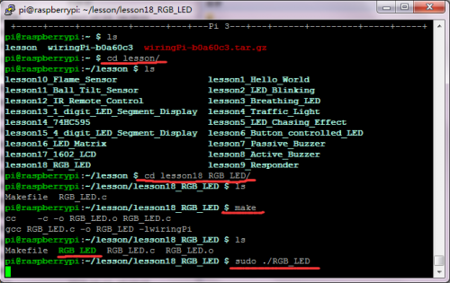
b. In the terminal input cd lesson18_RGB_LED to enter the folder.
c. In the terminal execute make to generate an RGB_LED executable file inside the folder.
d. Wiring as the above diagram, then enter the lesson18_RGB_LED folder, execute sudo ./RGB_LED at the terminal.
RGB light will display different colors.
e. Ctrl + c can exit the processing program.
5. Sample Code
#include <wiringPi.h>
#include <softPwm.h>
#include <stdio.h>

#define LedPinRed    0
#define LedPinGreen  1
#define LedPinBlue   2

int colors[] = {0xFF0000, 0x00FF00, 0x0000FF, 0xFFFF00, 0x00FFFF, 0xFF00FF, 0xFFFFFF, 0x9400D3};

/******************************************************************************************
*A number is linear mapped from a range to another one, for example, a number from 0 to 100 is mapped to 0 ~ 255.
******************************************************************************************/
int map(int x, int in_min, int in_max, int out_min, int out_max)
{
    return (x -in_min) * (out_max - out_min) / (in_max - in_min) + out_min;
}

void ledInit(void)
{
    softPwmCreate(LedPinRed,  0, 100);  //create a soft pwm, original duty cycle is 0Hz, range is 0~100
    softPwmCreate(LedPinGreen,0, 100);
    softPwmCreate(LedPinBlue, 0, 100);
}

void ledColorSet(int color)        //set color, for example: 0xde3f47
{
    int r_val, g_val, b_val;

    r_val = (color & 0xFF0000) >> 16;  //get red value
    g_val = (color & 0x00FF00) >> 8;   //get green value
    b_val = (color & 0x0000FF) >> 0;   //get blue value

    r_val = map(r_val, 0, 255, 0, 100);   //change a num(0~255) to 0~100
    g_val = map(g_val, 0, 255, 0, 100);
    b_val = map(b_val, 0, 255, 0, 100);

    softPwmWrite(LedPinRed,   100 - r_val);  //change duty cycle
    softPwmWrite(LedPinGreen, 100 - g_val);
    softPwmWrite(LedPinBlue,  100 - b_val);
}

int main(void)
{
    int i;

    if(wiringPiSetup() == -1){      //when initialize wiringPi failed, print message to screen
        printf("setup wiringPi failed !\n");
        return 1;
    }

    ledInit();

    while(1){
        for(i = 0; i < sizeof(colors)/sizeof(int); i++){
            ledColorSet(colors[i]);
            delay(500);
        }
    }

    return 0;
}
Lesson 19: 9g Servo Control
1. Introduction
The rotate angle of servo motor is controlled by regulating the duty cycle of the PWM (Pulse-Width Modulation) signal. The standard cycle of the PWM signal is 20ms (50Hz). In the experiment, we use two signals with 1ms~2ms of pulse width and 20ms of cycle, to control the rotation of servo motor, making it swings back and forth at the corresponding angle of the two signals.
2. Hardware Required
- Servo Motor*1
- Keyestudio RPI GPIO-PCF8591 Shield*1
- USB Cable*1
- Raspberry Motherboard*1
4. Programming
a. Use winSCP to put the lesson19_Servo into the lesson folder of raspberry system.
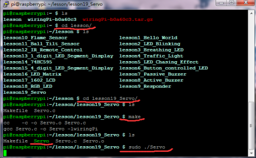
b. In the terminal, input cd lesson19_Servo to enter the folder.
c. In the terminal, execute make to generate a Servo executable file inside the folder.
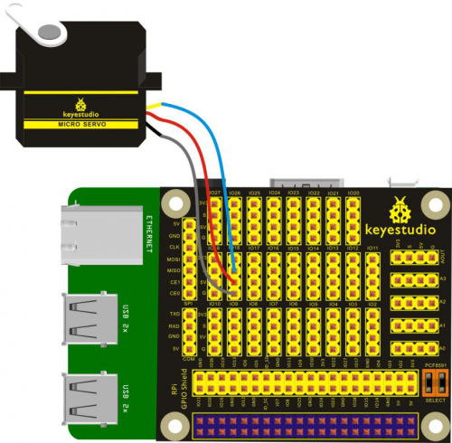
d. Wiring as the above diagram, then enter the lesson19_Servo folder, execute sudo ./Servo at the terminal. Servo motor will swing continually.
e. Ctrl + c can exit the processing program.
5. Source Code
#include <wiringPi.h>
int main()
{
	wiringPiSetup();
	pinMode(1,OUTPUT);
	int i;
	for(;;)
	{

		for(i=0;i<50;i++)
		{
		digitalWrite(1,HIGH);
		delayMicroseconds(1000);
		digitalWrite(1,LOW);
      delay(19);
		}

		delay(1000);

		for(i=0;i<50;i++)
		{
		digitalWrite(1,HIGH);
		delayMicroseconds(2000);
		digitalWrite(1,LOW);
	        delay(18);
		}
                delay(1000);
	}
	return 0;
}
Lesson 20: ULN2003 Stepper Motor
1. Introduction
In this lesson, we will drive the stepper motor to turn only one circle by directly connecting ULN2003 Stepper Motor Driver to RPI GPIO-PCF8591 Shield.
2. Hardware Required
- Keyestudio 5V 4-Phase Stepper Motor + Driver Board ULN2003*1
- Keyestudio RPI GPIO-PCF8591 Shield*1
- USB Cable*1
- Raspberry Motherboard*1
- Dupont Wires* Several
4. Programming
a. Use winSCP to put the lesson20_ULN2003 into the lesson folder of raspberry system.
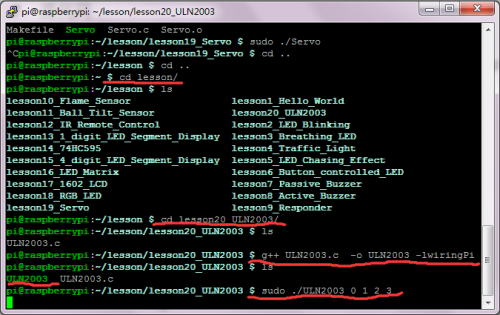
b. In the terminal, input cd lesson and cd lesson20_ULN2003 to enter the folder.
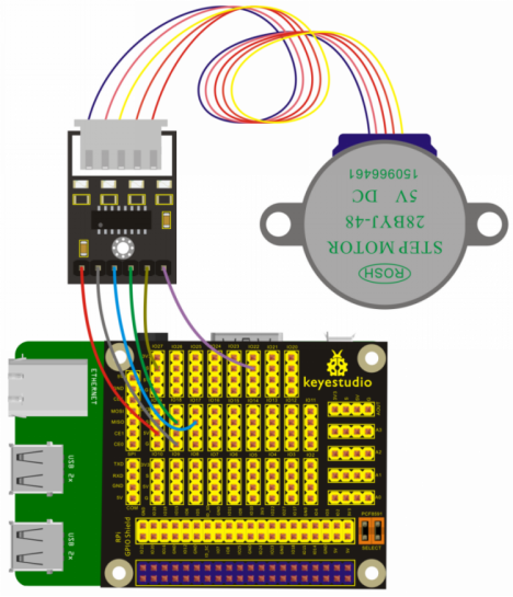
c. Wiring as the above diagram, then enter the lesson20_ULN2003 folder, execute g++ ULN2003.c -o ULN2003 -lwiringPi and sudo ./ULN2003 0 1 2 3, it can drive the stepper motor to turn one circle.
5. Sample Code
/* moto.c
* A program to control a stepper motor through the GPIO on Raspberry Pi.
* Author: Darran Zhang (http://www.codelast.com)
*/
#include <wiringPi.h>
#include <stdio.h>
#include <unistd.h>
#include <stdlib.h>

#define CLOCKWISE 1
#define COUNTER_CLOCKWISE 2
void delayMS(int x);
void rotate(int* pins, int direction);
int main(int argc,char* argv[]) {
  if (argc < 4) {
    printf("Usage example: ./motor 0 1 2 3 \n");
    return 1;
  }

  /* number of the pins which connected to the stepper motor driver board */
  int pinA = atoi(argv[1]);
  int pinB = atoi(argv[2]);
  int pinC = atoi(argv[3]);
  int pinD = atoi(argv[4]);

  int pins[4] = {pinA, pinB, pinC, pinD};

  if (-1 == wiringPiSetup()) {
    printf("Setup wiringPi failed!");
    return 1;
  }

  /* set mode to output */
  pinMode(pinA, OUTPUT);
  pinMode(pinB, OUTPUT);
  pinMode(pinC, OUTPUT);
  pinMode(pinD, OUTPUT);

  delayMS(50);    // wait for a stable status
  for (int i = 0; i < 500; i++) {
    rotate(pins, CLOCKWISE);
  }

  return 0;
}

/* Suspend execution for x milliseconds intervals.
 *  @param ms Milliseconds to sleep.
 */
void delayMS(int x) {
  usleep(x * 1000);
}

/* Rotate the motor.
 *  @param pins     A pointer which points to the pins number array.
 *  @param direction  CLOCKWISE for clockwise rotation, COUNTER_CLOCKWISE for counter clockwise rotation.
 */
void rotate(int* pins, int direction) {
  for (int i = 0; i < 4; i++) {
    if (CLOCKWISE == direction) {
      for (int j = 0; j < 4; j++) {
        if (j == i) {
          digitalWrite(pins[3 - j], 1); // output a high level
        } else {
          digitalWrite(pins[3 - j], 0); // output a low level
        }
      }
    } else if (COUNTER_CLOCKWISE == direction) {
      for (int j = 0; j < 4; j++) {
        if (j == i) {
          digitalWrite(pins[j], 1); // output a high level
        } else {
          digitalWrite(pins[j], 0); // output a low level
        }
      }
    }
    delayMS(4);
  }
}
Lesson 21: Photo Resistor
1. Introduction
In the lesson, we will connect Photo Resistor to Keyestudio RPI GPIO-PCF8591 Shield to test the extended AD function of raspberry pi. We will directly connect an external photo resistor to test the illumination intensity, and then use the measured value to control LED’s on and off.
2. Hardware Required
- Photo Resistor*1
- LED - Red*1
- 10KΩ Resistor*1
- 220Ω Resistor*1
- RPI GPIO Shield*1
- 40 Pin Colorful Jumper Wires*1
- Keyestudio RPI GPIO-PCF8591 Shield*1
- Breadboard*1
- USB Cable*1
- Raspberry Motherboard*1
- Jumper Breadboard Wires* Several
- Dupont Wire* Several
4. Programming
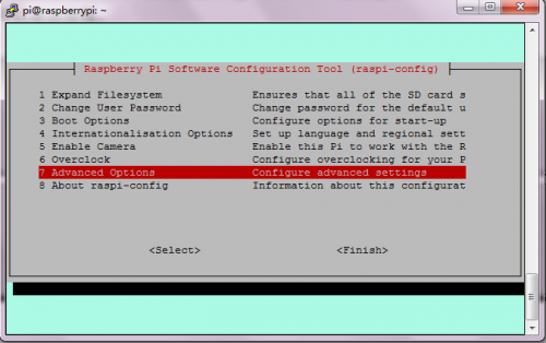
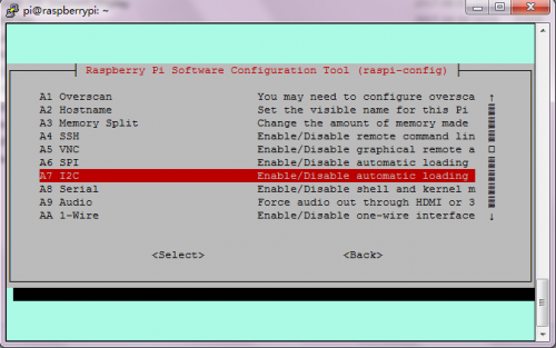
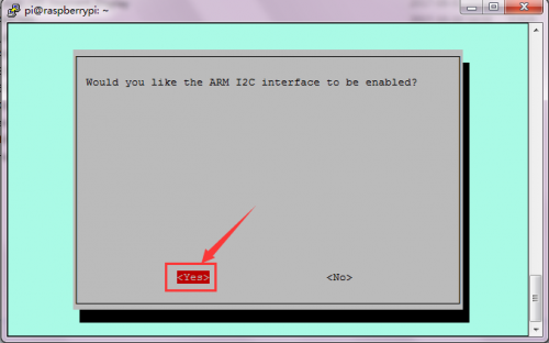
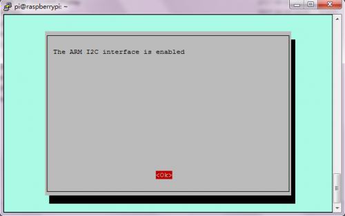
a. Raspberry pi default not open the I2C function, on the terminal, input sudo raspi-config to open raspberry configuration interface.
b. Select the 7 Advanced Options, then select the A7 I2C option to enable the raspberry pi I2C function.
c. Use winSCP to put the lesson21_Photo_Resistor into the lesson folder of raspberry system.
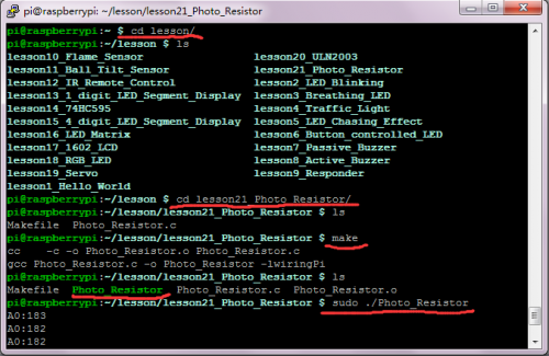
d. In the terminal, input cd lesson and cd lesson21_Photo_Resistor to enter the folder.
e. In the terminal, execute make to generate a Photo_Resistor executable file inside the folder.
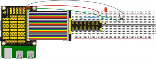
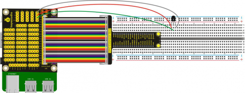
f. Wiring as the above diagram, then enter the lesson21_Photo_Resistor folder, execute sudo ./Photo_Resistor at the terminal. Then, you can see the value(0-255) representing the illumination intensity; when the value is greater than 150, LED lights up.
g. Ctrl + c can exit the processing program.
Please refer to the figure below:
5. Source Code
#include <wiringPi.h>
#include <pcf8591.h>
#include <stdio.h>

#define Address 0x48
#define BASE 64
#define A0 BASE+0
#define A1 BASE+1
#define A2 BASE+2
#define A3 BASE+3

int main(void)
{
      unsigned char value;
	wiringPiSetup();
      pinMode(1,OUTPUT);
	pcf8591Setup(BASE,Address);

	while(1)
	{
        value=analogRead(A0);
        printf("A0:%d\n",value);
        delay(100);
        if(value>150)
        {
         digitalWrite(1,HIGH);
         delay(100);
        }
        else
        {
         digitalWrite(1,LOW);
        }
	}
     }
Lesson 22: LM35 Temp Sensor
1. Introduction
This lesson will use AD transfer function of RPI GPIO-PCF8591 Shield. In the test, we will directly connect an external LM35 Temp Sensor to test the current temperature, you can see the corresponding value on the terminal of raspberry pi.
2. Hardware Required
- LM35 Temp Sensor*1
- RPI GPIO Shield*1
- 40 pin Colorful Jumper Wires*1
- Keyestudio RPI GPIO-PCF8591 Shield*1
- Breadboard*1
- USB Cable *1
- Raspberry Motherboard * 1
- Dupont Wires* several
4. Programming
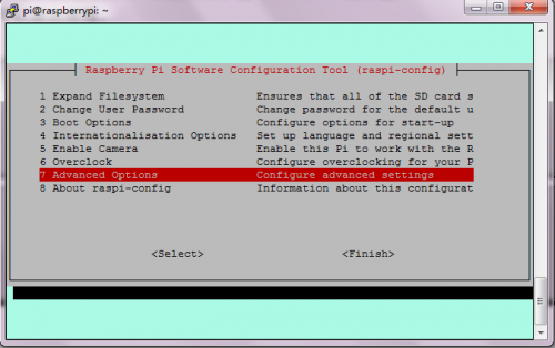
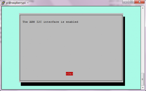
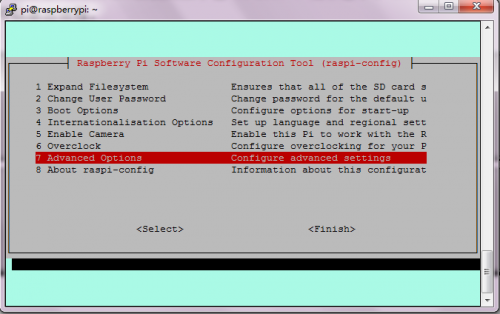
a. Raspberry pi default not open the I2C function, on the terminal, input sudo raspi-config to open raspberry configuration interface.
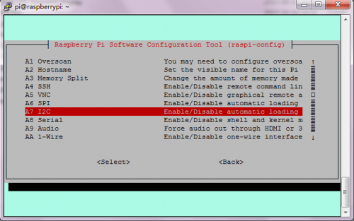
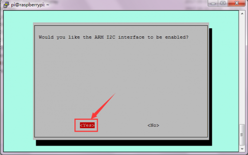
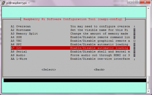
b. Select the 7 Advanced Options, then select the A7 I2C option to enable the raspberry pi I2C function.
c. Use winSCP to put the lesson22_LM35 into the lesson folder of raspberry system.
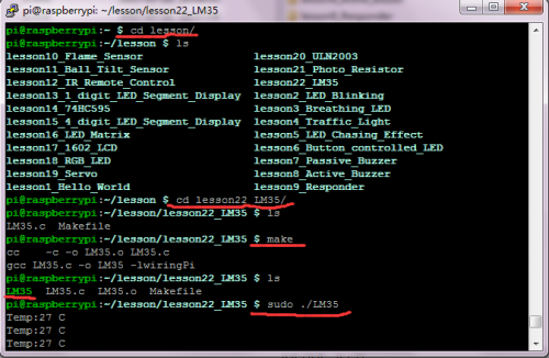
d. In the terminal, input cd lesson and cd lesson22_LM35 to enter the folder.
e. In the terminal, execute make to generate LM35 executable file inside the folder.
f. Wiring as the above diagram, then enter the lesson22_LM35 folder, execute sudo ./LM35 at the terminal. Then, you can see the temp value of current environment.
Please refer to the figure below:
5. Source Code
#include <wiringPi.h>
#include <pcf8591.h>
#include <stdio.h>

#define Address 0x48
#define BASE 64
#define A0 BASE+0
#define A1 BASE+1
#define A2 BASE+2
#define A3 BASE+3

int main(void)
{
        unsigned char value;
	wiringPiSetup();
	pcf8591Setup(BASE,Address);

	while(1)
	{
               value=analogRead(A0);
               value=(500 * value) /256;
               printf("Temp:%d C\n",value);
               delay(50);

	}
}
Lesson 23: pcf8591
1. Introduction
Raspberry Pi itself does not have AD/ DA function, and if the raspberry pi need to connect an external analog sensor, it first must connect an external AD/DA function expansion board. This pcf8591 can use the I2C interface of raspberry pi to extend the 4-way AD and 1-way DA.
In this course, we will connect a 10KΩ potentiometer to the Keyestudio RPI GPIO-PCF8591 Shield to test the extended AD function of raspberry pi.
2. Hardware Required
- 10KΩ Potentiometer*1
- RPI GPIO Shield*1
- 40 pin Colorful Jumper Wires*1
- Keyestudio RPI GPIO-PCF8591 Shield*1
- Breadboard*1
- USB Cable* 1
- Raspberry Motherboard * 1
- Dupont Wires* several
4. Programming
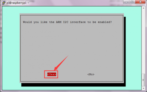
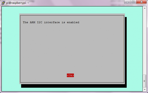
a. Raspberry pi default not open the I2C function, on the terminal, input sudo raspi-config to open raspberry configuration interface.
b. Select the 7 Advanced Options, then select the A7 I2C option to enable the raspberry pi I2C function.
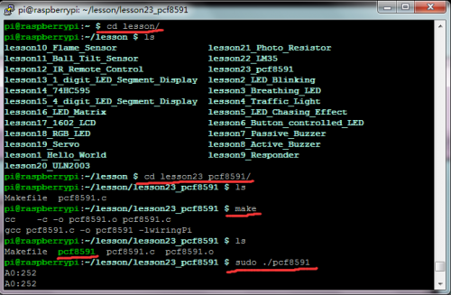
c. Use winSCP to put the lesson23_pcf8591 into the lesson folder of raspberry system.
d. In the terminal, input cd lesson and cd lesson23_pcf8591 to enter the folder.
e. In the terminal, execute make to generate a pcf8591 executable file inside the folder.
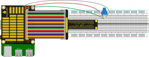
f. Wiring as the above diagram, enter the lesson23_pcf8591 folder, then execute sudo ./pcf8591 at the terminal. Then, you can see the corresponding value(0-255)on the terminal.
g. Ctrl + c can exit the processing program.
Please refer to the figure below:
5. Source Code
#include <wiringPi.h>
#include <pcf8591.h>
#include <stdio.h>

#define Address 0x48         //pcf8591 Address
#define BASE 64
#define A0 BASE+0           //input address of A0
#define A1 BASE+1           //input address of A1
#define A2 BASE+2           //input address of A2
#define A3 BASE+3           //input address of A3
int main(void)
{
    unsigned char value;
	wiringPiSetup();
	pcf8591Setup(BASE,Address);        //configure pcf8591

	while(1)
	{
               value=analogRead(A0);     // read the value of A0 port
               printf("A0:%d\n",value);  // print the value of A0 on the terminal
               delay(100);
	}
}
Lesson 24: PIR Motion Sensor
1. Introduction
In this lesson, we will use PIR Motion Sensor to detect whether there is someone moving nearby. If someone moves nearby, LED will light up, and the terminal prints the character "Somebody is in this area!". Otherwise, LED will go out and the terminal will print the character "No one!".
2. Hardware Required
- PIR Motion Sensor*1
- LED - Red*1
- 220Ω Resistor*1
- RPI GPIO Shield*1
- 40 pin Colorful Jumper Wires*1
- Keyestudio RPI GPIO-PCF8591 Shield*1
- Breadboard*1
- USB Cable * 1
- Raspberry Motherboard * 1
- Jumper Wires * several
- Dupont Wires* several
4. Programming
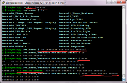
a. Use winSCP to put the lesson24_PIR_Motion_Sensor into the lesson folder of raspberry system.
b. In the terminal, input cd lesson24_PIR_Motion_Sensor to enter the folder.
c. In the terminal, execute make to generate PIR_Motion_Sensor executable file inside the folder.
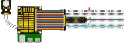
d. Wiring as the above diagram, then enter the lesson24_PIR_Motion_Sensor folder, execute sudo ./PIR_Motion_Sensor at the terminal. It can detect any movement nearby.
e. Ctrl + c can exit the processing program.
5. Source Code
#include <wiringPi.h>
#include <stdio.h>

int main()
{
  wiringPiSetup();
  char val;
  {
    pinMode(1,INPUT);
    pinMode(2,OUTPUT);
  }

  while(1)
  {
   val=digitalRead(1);
   if(val==1)
  {
   printf("Somebody is in this area!\n");
   digitalWrite(2,HIGH);
   delay(100);
  }

   else
  {
   printf("No one!\n");
   digitalWrite(2,LOW);
   delay(100);
  }
  }
}
Lesson 25: MQ-2 Analog Gas Sensor
1. Introduction
In the previous lesson, we have connected the Analog Rotation Sensor to the Keyestudio RPI GPIO-PCF8591 Shield to test the raspberry-extended AD function. In this lesson, we will directly connect an external MQ-2 sensor module to test the liquefied petroleum gas, propane, hydrogen and other gas content in the air, and you can see the corresponding value at the raspberry pi terminal.
2. Hardware Required
- Analog Gas Sensor*1
- Keyestudio RPI GPIO-PCF8591 Shield*1
- USB Cable * 1
- Raspberry Motherboard * 1
- Dupont Wires* several
4. Programming
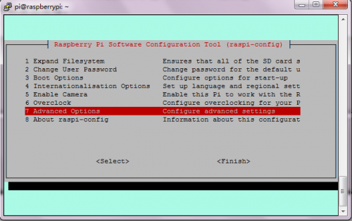
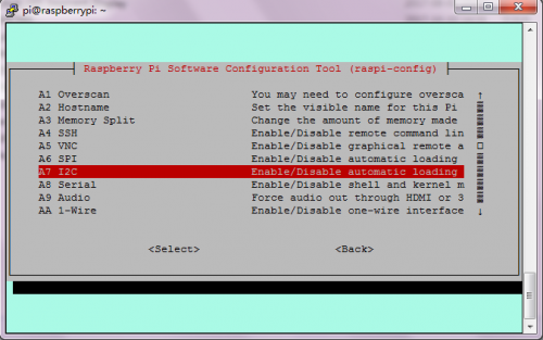
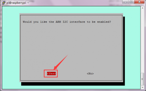
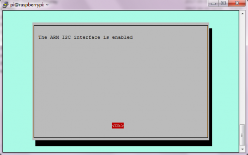
a. Raspberry pi default not open the I2C function, on the terminal, input sudo raspi-config to open raspberry pi configuration interface.
b. Select the 7 Advanced Options, then select the A7 I2C option to enable the raspberry pi I2C function.
c. Use winSCP to put the lesson25_MQ-2 into the lesson folder of raspberry system.
d. In the terminal, input cd lesson and cd lesson25_MQ-2 to enter the folder.
e. In the terminal, execute make to create a MQ-2 executable file inside the folder.
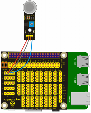
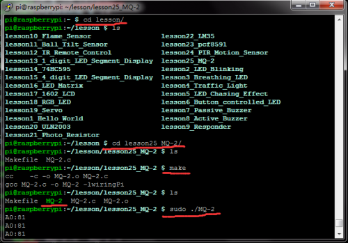
f. Wiring as the above diagram, then enter the lesson25_MQ-2 folder, execute sudo ./MQ-2 at the terminal.
Then, on the terminal, you can see the value(0-255)representing the gas content. There are two LEDs on the sensor, including one power indicator, and one digital output indicator. And you can adjust the sensitivity by rotating the potentiometer. When the sensor doesn’t detect gas, digital LED goes out and digital port outputs high level; while detecting the gas, digital LED lights up and digital port outputs low level.
g. Ctrl + c can exit the processing program.
Please refer to the figure below:
5. Source Code
#include <wiringPi.h>
#include <pcf8591.h>
#include <stdio.h>

#define Address 0x48
#define BASE 64
#define A0 BASE+0
#define A1 BASE+1
#define A2 BASE+2
#define A3 BASE+3

int main(void)
{
      unsigned char value;
	wiringPiSetup();
      pinMode(1,OUTPUT);
	pcf8591Setup(BASE,Address);

	while(1)
	{
        value=analogRead(A0);
        printf("A0:%d\n",value);
        delay(100);
	}
     }
Lesson 26: ADXL345 Acceleration Module
1. Introduction
In this course, we will directly connect ADXL345 Three Axis Acceleration Module to the Keyestudio RPI GPIO-PCF8591 Shield, then swing ADXL345, getting different three-axis value in the terminal.
2. Hardware Required
- ADXL345 Three Axis Acceleration Module*1
- Keyestudio RPI GPIO-PCF8591 Shield*1
- USB Cable * 1
- Raspberry Motherboard * 1
- Dupont Wires* several
4. Programming
a. Raspberry pi default not open the I2C function, on the terminal, input sudo raspi-config to open raspberry configuration interface.
b. Select the 7 Advanced Options, then select the A7 I2C option to enable the raspberry pi I2C function.
c. Use winSCP to put the lesson26_ADXL345 into the lesson folder of raspberry system.
d. In the terminal, input cd lesson and cd lesson26_ADXL345 to enter the folder.
e. In the terminal, execute make to generate an ADXL345 executable file inside the folder.
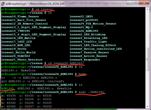
f. Wiring as the above diagram, then enter the lesson26_ADXL345 folder, execute sudo ./ADXL345 at the terminal. Then, swing ADXL345 sensor, you can get different three-axis value in the terminal.
g. Ctrl + c can exit the processing program.
Please refer to the figure below:


5. Source Code
#include <wiringPiI2C.h>
#include <stdio.h>
#include <stdlib.h>
#include <errno.h>

#define  DevAddr  0x53  //device address

struct acc_dat{
	int x;
	int y;
	int z;
};

void adxl345_init(int fd)
{
	wiringPiI2CWriteReg8(fd, 0x31, 0x0b);
	wiringPiI2CWriteReg8(fd, 0x2d, 0x08);
//	wiringPiI2CWriteReg8(fd, 0x2e, 0x00);
	wiringPiI2CWriteReg8(fd, 0x1e, 0x00);
	wiringPiI2CWriteReg8(fd, 0x1f, 0x00);
	wiringPiI2CWriteReg8(fd, 0x20, 0x00);

	wiringPiI2CWriteReg8(fd, 0x21, 0x00);
	wiringPiI2CWriteReg8(fd, 0x22, 0x00);
	wiringPiI2CWriteReg8(fd, 0x23, 0x00);

	wiringPiI2CWriteReg8(fd, 0x24, 0x01);
	wiringPiI2CWriteReg8(fd, 0x25, 0x0f);
	wiringPiI2CWriteReg8(fd, 0x26, 0x2b);
	wiringPiI2CWriteReg8(fd, 0x27, 0x00);

	wiringPiI2CWriteReg8(fd, 0x28, 0x09);
	wiringPiI2CWriteReg8(fd, 0x29, 0xff);
	wiringPiI2CWriteReg8(fd, 0x2a, 0x80);
	wiringPiI2CWriteReg8(fd, 0x2c, 0x0a);
	wiringPiI2CWriteReg8(fd, 0x2f, 0x00);
	wiringPiI2CWriteReg8(fd, 0x38, 0x9f);
}

struct acc_dat adxl345_read_xyz(int fd)
{
	char x0, y0, z0, x1, y1, z1;
	struct acc_dat acc_xyz;

	x0 = 0xff - wiringPiI2CReadReg8(fd, 0x32);
	x1 = 0xff - wiringPiI2CReadReg8(fd, 0x33);
	y0 = 0xff - wiringPiI2CReadReg8(fd, 0x34);
	y1 = 0xff - wiringPiI2CReadReg8(fd, 0x35);
	z0 = 0xff - wiringPiI2CReadReg8(fd, 0x36);
	z1 = 0xff - wiringPiI2CReadReg8(fd, 0x37);

	acc_xyz.x = (int)(x1 << 8) + (int)x0;
	acc_xyz.y = (int)(y1 << 8) + (int)y0;
	acc_xyz.z = (int)(z1 << 8) + (int)z0;

	return acc_xyz;
}

int main(void)
{
	int fd;
	struct acc_dat acc_xyz;

	fd = wiringPiI2CSetup(DevAddr);

	if(-1 == fd){
		perror("I2C device setup error");
	}

	adxl345_init(fd);

	while(1){
		acc_xyz = adxl345_read_xyz(fd);
		printf("x: %05d  y: %05d  z: %05d\n", acc_xyz.x, acc_xyz.y, acc_xyz.z);

		delay(100);
	}

	return 0;
}
Lesson 27: Ultrasonic Sensor
1. Introduction
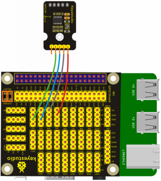
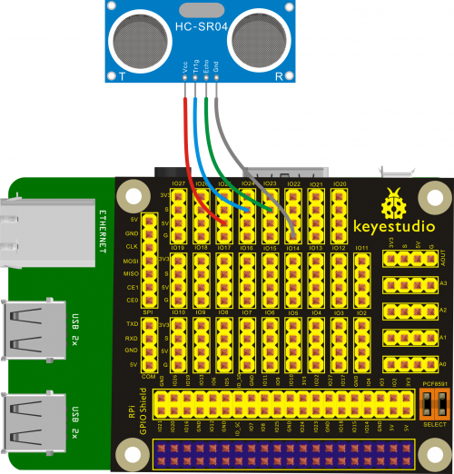
In the lesson, HC-SR04 Ultrasonic Sensor is connected to Keyestudio RPI GPIO-PCF8591 Shield, you can see the distance value of ultrasonic detection on the terminal.
2. Hardware Required
- HC-SR04 Ultrasonic Sensor*1
- Keyestudio RPI GPIO-PCF8591 Shield*1
- USB Cable * 1
- Raspberry Motherboard * 1
- Dupont Wires* several
4. Programming
a. Use winSCP to put the lesson27_Ultrasonic into the lesson folder of raspberry system.
b. In the terminal, input cd lesson27_Ultrasonic to enter the folder.
c. In the terminal, execute make to generate Ultrasonic executable file inside the folder.
d. Wiring as the above diagram, then enter the lesson27_Ultrasonic folder, execute sudo ./Ultrasonic at the terminal. Then, you can see the distance value of ultrasonic detection on the terminal.
e. Ctrl + c can exit the processing program.
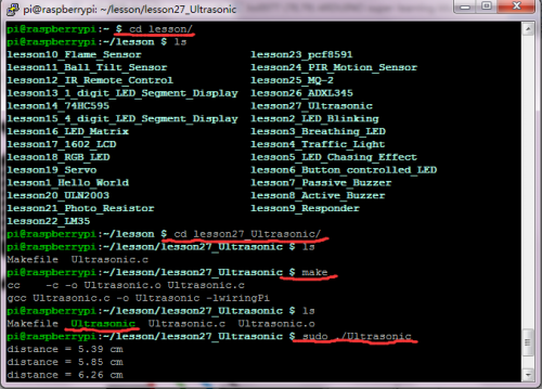
5. Source Code
#include <wiringPi.h>
#include <stdio.h>
#include <sys/time.h>

#define Trig    5
#define Echo   4
void ultraInit(void)
{
	pinMode(Echo, INPUT);
	pinMode(Trig, OUTPUT);
}

float disMeasure(void)
{
	struct timeval tv1;
	struct timeval tv2;
	long start, stop;
	float dis;

	digitalWrite(Trig, LOW);
	delayMicroseconds(2);

	digitalWrite(Trig, HIGH);
	delayMicroseconds(10);
    digitalWrite(Trig, LOW);

	while(!(digitalRead(Echo) == 1));
	gettimeofday(&tv1, NULL);

	while(!(digitalRead(Echo) == 0));
	gettimeofday(&tv2, NULL);

	start = tv1.tv_sec * 1000000 + tv1.tv_usec;
	stop  = tv2.tv_sec * 1000000 + tv2.tv_usec;

	dis = (float)(stop - start) / 1000000 * 34000 / 2;

	return dis;
}

int main(void)
{
	float dis;

	if(wiringPiSetup() == -1){ //when initialize wiring failed,print messageto screen
		printf("setup wiringPi failed !");
		return 1;
	}

	ultraInit();

	while(1){
		dis = disMeasure();
		printf("distance = %0.2f cm\n",dis);
		delay(500);
	}

	return 0;
}
Lesson 28: Joystick Module
1. Introduction
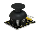
Joystick Module is made of original premium metal PS2 rocker potentiometer with (X, Y) 2-axis analog output, (Z) 1-way button digital output.
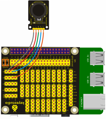
In the previous lesson, we have connected the 10KΩpotentiometer to the Keyestudio RPI GPIO-PCF8591 Shield to test the raspberry-extended AD function. In this course, we will connect Joystick Module to the Keyestudio RPI GPIO-PCF8591 Shield, after running the program, you can see the input value of Joystick Module x, y-dimension, and the output value of z-dimension on the terminal.
2. Hardware Required
- Joystick Module*1
- Keyestudio RPI GPIO-PCF8591 Shield
- USB Cable * 1
- Raspberry Motherboard * 1
- Dupont Wires* several
4. Programming
a. Raspberry pi default not open the I2C function, on the terminal, input sudo raspi-config to open raspberry configuration interface.
b. Select the 7 Advanced Options, then select the A7 I2C option to enable the raspberry pi I2C function.
c. Use winSCP to put the lesson28_Joystick_Module into the lesson folder of raspberry system.
d. In the terminal, input cd lesson and cd lesson28_Joystick_Module to enter the folder.
e. In the terminal, execute make to generate a Joystick_Module executable file inside the folder.
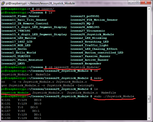
f. Wiring as the above diagram, enter thelesson28_Joystick_Module folder, then execute sudo ./Joystick_Module at the terminal. Then, you can see the input value of Joystick Module x, y-dimension, and the output value of z-dimension on the terminal.
g. Ctrl + c can exit the processing program.
Please refer to the figure below:


5. Source Code
#include <wiringPi.h>
#include <pcf8591.h>
#include <stdio.h>

#define Address 0x48
#define BASE 64
#define A0 BASE+0
#define A1 BASE+1
#define A2 BASE+2
#define A3 BASE+3
char dat;

int main(void)
{
        unsigned char value;
	wiringPiSetup();
        pinMode(1,INPUT);
	pcf8591Setup(BASE,Address);
	while(1)
	{
               value=analogRead(A0);
               printf("X:%d    ",value);
               value=analogRead(A1);
               printf("Y:%d    ",value);
               dat=digitalRead(1);
               if(dat==HIGH)
                  printf("DO:%d\n",dat);
               if(dat==LOW)
                  printf("DO:%d\n",dat);
               delay(100);

               // analogWrite(BASE,value++);
               // printf("AOUT:%d\n",value++);
               // delay(50);
	}
}
Lesson 29: 5V Relay
1. Introduction
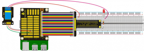
In this lesson, we just simply test the 5V relay. The relay is available for high level, when the signal end inputs high level, the "ON" side is closed, LED lights up; otherwise it will be disconnected, LED off. In the experiment, we just make the relay closed for 0.5S, then disconnected for 0.5S, repeatedly cycle.
2. Hardware Required
- Relay Module*1
- LED - Red *1
- 220Ω Resistor*1
- RPI GPIO Shield*1
- 40 pin Colorful Jumper Wires*1
- Keyestudio RPI GPIO-PCF8591 Shield*1
- Breadboard*1
- USB Cable * 1
- Raspberry Motherboard * 1
- Dupont Wires* several
- Jumper Wires* several
4. Programming
a. Use winSCP to put the lesson29_5V_Relay into the lesson folder of raspberry system.
b. In the terminal, input cd lesson29_5V_Relay to enter the folder.
c. In the terminal, execute make to generate a 5V_Relay executable file inside the folder.
d. Wiring as the above diagram, then enter the lesson29_5V_Relay folder, execute sudo ./5V_Relay at the terminal. It can achieve the effect of blinking LED.
e. Ctrl + c can exit the processing program.
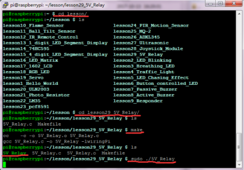
5. Source Code
#include <wiringPi.h>
int main()
{
  wiringPiSetup();

  {
        pinMode(1,OUTPUT);
  }

  while(1)
  {
        digitalWrite(1,HIGH);
        delay(500);
        digitalWrite(1,LOW);
        delay(500);
  }

}
Lesson 30: DHT11 Temp and Humidity Sensor
1. Introduction
This lesson will directly connect DHT11 Temperature and Humidity Sensor to Keyestudio RPI GPIO-PCF8591 Shield to test the temperature and humidity of current environment, and you can see the corresponding value on the terminal of raspberry pi.
2. Hardware Required
- DHT11 Temperature and Humidity Sensor*1
- Keyestudio RPI GPIO-PCF8591 Shield*1
- USB Cable * 1
- Raspberry Motherboard * 1
- Dupont Wires* several
4. Programming
a. Use winSCP to put the lesson30_DHT11 into the lesson folder of raspberry system.
b. In the terminal, input cd lesson30_DHT11 to enter the folder.
c. In the terminal, execute make to generate DHT11 executable file inside the folder.
d. Wiring as the above diagram, then enter the lesson30_DHT11 folder, execute sudo ./DHT11 at the terminal. Then, you can see the corresponding temperature and humidity value of current environment on the terminal.
e. Ctrl + c can exit the processing program.
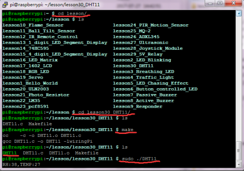
5. Source Code
#include <wiringPi.h>
#include <stdio.h>
#include <stdlib.h>
#include <stdint.h>
#define MAX_TIME 85
#define DHT11PIN 1
#define ATTEMPTS 5                 //retry 5 times when no response
int dht11_val[5]={0,0,0,0,0};

int dht11_read_val(){
    uint8_t lststate=HIGH;         //last state
    uint8_t counter=0;
    uint8_t j=0,i;
    for(i=0;i<5;i++)
        dht11_val[i]=0;

    //host send start signal
    pinMode(DHT11PIN,OUTPUT);      //set pin to output
    digitalWrite(DHT11PIN,LOW);    //set to low at least 18ms
    delay(18);
    digitalWrite(DHT11PIN,HIGH);   //set to high 20-40us
    delayMicroseconds(40);

    //start recieve dht response
    pinMode(DHT11PIN,INPUT);       //set pin to input
    for(i=0;i<MAX_TIME;i++)
    {
        counter=0;
        while(digitalRead(DHT11PIN)==lststate){  //read pin state to see if dht responsed. if dht always high for 255 + 1 times, break this while circle
            counter++;
            delayMicroseconds(1);
            if(counter==255)
                break;
        }
        lststate=digitalRead(DHT11PIN);   //read current state and store as last state.
        if(counter==255)         //if dht always high for 255 + 1 times, break this for circle
            break;
        // top 3 transistions are ignored, maybe aim to wait for dht finish response signal
        if((i>=4)&&(i%2==0)){
            dht11_val[j/8]<<=1;                     //write 1 bit to 0 by moving left (auto add 0)
            if(counter>16)                          //long mean 1
                dht11_val[j/8]|=1;                  //write 1 bit to 1
            j++;
        }
    }
    // verify checksum and print the verified data
    if((j>=40)&&(dht11_val[4]==((dht11_val[0]+dht11_val[1]+dht11_val[2]+dht11_val[3])& 0xFF))){
        printf("RH:%d,TEMP:%d\n",dht11_val[0],dht11_val[2]);
        return 1;
    }
    else
        return 0;
}

int main(void){
    int attempts=ATTEMPTS;
    if(wiringPiSetup()==-1)
        exit(1);
    while(attempts){                        //you have 5 times to retry
        int success = dht11_read_val();     //get result including printing out
        if (success) {            //if get result, quit program; if not, retry 5 times then quit
            break;
        }
        attempts--;
        delay(2500);
    }
    return 0;
}
Lesson 31: Soil Humidity Sensor
1. Introduction
This lesson we will directly connect an external soil humidity sensor to test the humidity of soil, and you can see the corresponding value on the terminal of raspberry pi.
2. Hardware Required
- Soil Humidity Sensor*1
- Keyestudio RPI GPIO-PCF8591 Shield*1
- USB Cable * 1
- Raspberry Motherboard * 1
- Dupont Wires* several
4. Programming
a. Raspberry pi default not open the I2C function, on the terminal, input sudo raspi-config to open raspberry configuration interface.
b. Select the 7 Advanced Options, then select the A7 I2C option to enable the raspberry pi I2C function.
c. Use winSCP to put the lesson31_ Soil_Humidity into the lesson folder of raspberry system.
d. In the terminal, input cd lesson and cd lesson31_ Soil_Humidity to enter the folder.
e. In the terminal, execute make to generate Soil_Humidity executable file inside the folder.
f. Wiring as the above diagram, then enter the lesson31_ Soil_Humidity folder, execute sudo ./Soil_Humidity at the terminal. Then, you can see the value of soil humidity(0-255) on the terminal.
g. Ctrl + c can exit the processing program.
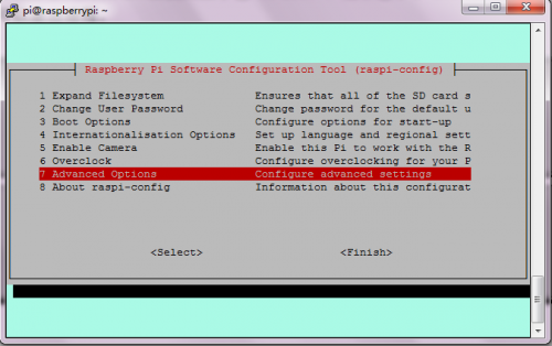
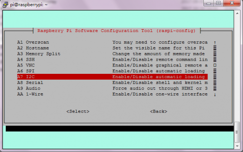
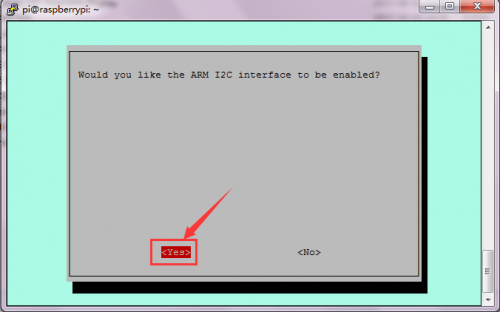
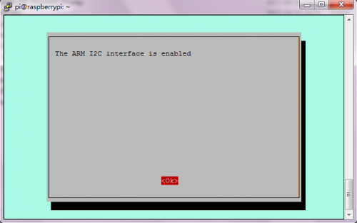
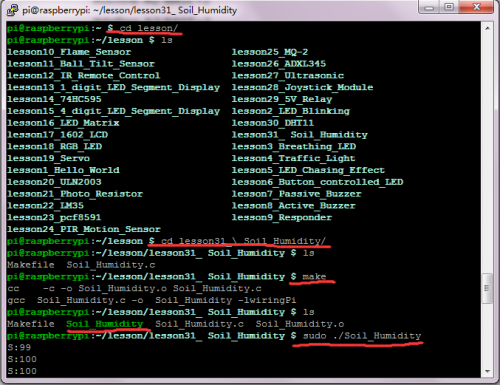
5. Source Code
#include <wiringPi.h>
#include <pcf8591.h>
#include <stdio.h>

#define Address 0x48
#define BASE 64
#define A0 BASE+0
#define A1 BASE+1
#define A2 BASE+2
#define A3 BASE+3

int main(void)
{
    unsigned char value;
	wiringPiSetup();
	pcf8591Setup(BASE,Address);

	while(1)
	{
               value=analogRead(A0);
               printf("S:%d\n",value);
               delay(50);
	}
}
Lesson 32: DS3231 Clock Module
1. Introduction
This lesson will mainly use DS3231 Clock Module. In the lesson, you can see the setting time regarded as the starting time to start accurate timing on the terminal.
2. Hardware Required
- DS3231 Clock Module*1
- Keyestudio RPI GPIO-PCF8591 Shield*1
- USB Cable* 1
- Raspberry Motherboard * 1
- Dupont Wires* several
4. Programming
a. This lesson will use the bcm2835 library function, and we have provided you with the installation package. First put winSCP compressed files into the system, and then input tar-xzf bcm2835-1.50.tar.gz on the terminal to extract the file.
b. On the terminal, input cd bcm2835-1.50 to enter inside the bcm2835-1.50 folder, then execute:
./configure
make
sudo make check
sudo make install
Installation finished
c. Use winSCP to put the lesson32_ DS3231 into the lesson folder of raspberry system.
d. In the terminal, input cd lesson and cd lesson32_ DS3231 to enter the folder.
e. In the terminal, input gcc –Wall DS3231.c –o DS3231 –lbcm2835, to generate DS3231 executable file inside the folder.
f. Wiring as the above diagram, then enter the lesson32_ DS3231 folder, execute sudo ./DS3231 at the terminal. Then, you can see the setting time regarded as the starting time to start accurate timing on the terminal.
g. Ctrl + c can exit the processing program.
Please refer to the figure below:
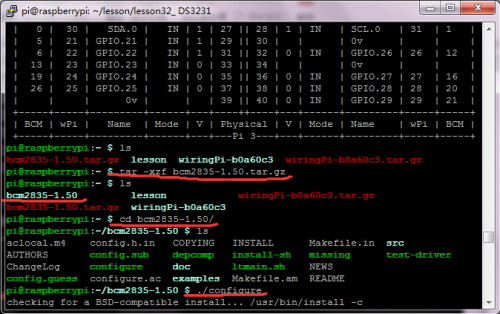
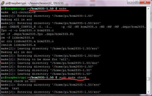
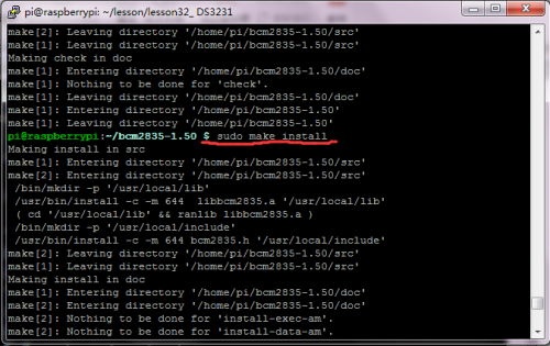
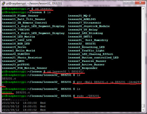
5. Source Code
#include <bcm2835.h>
#include <stdio.h>
#include <unistd.h>
//regaddr,seconds,minutes,hours,weekdays,days,months,yeas
char  buf[]={0x00,0x00,0x00,0x18,0x04,0x12,0x08,0x15};
char  *str[]  ={"SUN","Mon","Tues","Wed","Thur","Fri","Sat"};
void pcf8563SetTime()
{
    bcm2835_i2c_write(buf,8);
}

void pcf8563ReadTime()
{
    buf[0] = 0x00;
    bcm2835_i2c_write_read_rs(buf ,1, buf,7);
}

int main(int argc, char **argv)
{
    if (!bcm2835_init())return 1;
    bcm2835_i2c_begin();
    bcm2835_i2c_setSlaveAddress(0x68);
    bcm2835_i2c_set_baudrate(10000);
    printf("start..........\n");

    pcf8563SetTime();
    while(1)
    {
        pcf8563ReadTime();
        buf[0] = buf[0]&0x7F; //sec
        buf[1] = buf[1]&0x7F; //min
        buf[2] = buf[2]&0x3F; //hour
        buf[3] = buf[3]&0x07; //week
        buf[4] = buf[4]&0x3F; //day
        buf[5] = buf[5]&0x1F; //mouth
        //year/month/day
        printf("20%02x/%02x/%02x  ",buf[6],buf[5],buf[4]);
        //hour:minute/second
        printf("%02x:%02x:%02x  ",buf[2],buf[1],buf[0]);
        //weekday
        printf("%s\n",str[(unsigned char)buf[3]-1]);
        bcm2835_delay(1000);
    }

    bcm2835_i2c_end();
    bcm2835_close();

    return 0;
}
Documents
Datasheet PDF:
https://drive.google.com/open?id=1lEeNBrb33pAqof7IT0UsSELO_UAg9UV1
SDFormatter Tool:
https://www.sdcard.org/downloads/formatter_4/index.html
Raspberry Pi Download:
https://www.raspberrypi.org/downloads/
Install Wiringpi:
https://projects.drogon.net/raspberry-pi/wiringpi/download-and-install/
Download Mirror Image File:
https://www.raspberrypi.org/downloads/raspbian/
Buy From
Official Website: http://www.keyestudio.com/keyestudio-ultimate-starter-kit-for-raspberry-pi.html
Available on Amazon: [1]
Available on ebay: [2]
Available on AliExpress: [3]
