KS0326 Keyestudio Blue 9G Servo 3PCS: Difference between revisions
Keyestudio (talk | contribs) |
Keyestudio (talk | contribs) |
||
| Line 112: | Line 112: | ||
*[https://drive.google.com/open?id=1R5K48jiZtJht6eXZuLmNJx5qKiSf5ug_ Download the document ] | *[https://drive.google.com/open?id=1R5K48jiZtJht6eXZuLmNJx5qKiSf5ug_ Download the document ] | ||
| Line 121: | Line 122: | ||
*[https://www.amazon.com/KEYESTUDIO-compatible-Arduino-Helicopter-Airplane/dp/B07DRFFX9W From Amazon] | *[https://www.amazon.com/KEYESTUDIO-compatible-Arduino-Helicopter-Airplane/dp/B07DRFFX9W From Amazon] | ||
*[https://www.aliexpress.com/store/product/Free-shiping-1PCS-keyestudio-MINI-9G-Servo-Motor-23-12-2-29mm-Blue-For-Arduino-Robot/1452162_32791539971.html?spm=2114.12010612.8148356.4.31f63ce6OwRg21 From Aliexpress ] | |||
[[Category: Accessories]] | [[Category: Accessories]] | ||
Revision as of 13:32, 23 August 2018
Keyestudio Blue 9G Servo 3PCS
Introduction
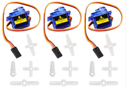
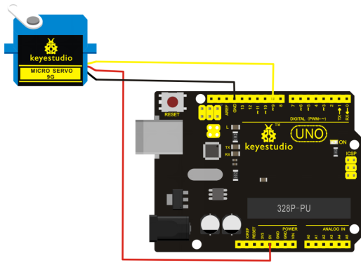
This kit mainly includes three micro servo motors with 90 degrees. The servo has three interfaces,distinguished by brown, red and orange line (different brand may have different color). Brown line is for GND, red one for power 5V, orange one for signal terminal (PWM signal).
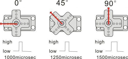
The rotation angle of servo is controlled by regulating the duty cycle of the PWM(Pulse-Width Modulation) signal. The standard cycle of the PWM signal is fixed at 20ms (50 Hz), and the pulse width is distributed between 1ms-1.5ms. The pulse width corresponds to the rotation angle ( 0°~90°) of servo.
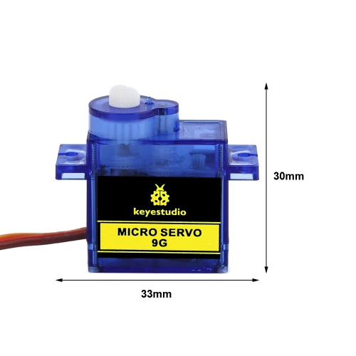
Dimensions
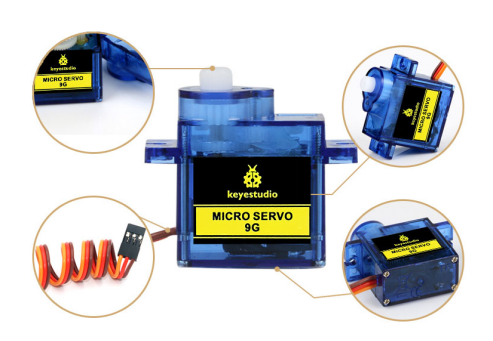
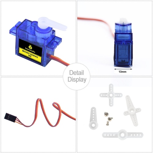
Details Display
Connection Diagram
Sample Program
There are two ways to control a servomotor with Arduino. One is to use a common digital sensor port of Arduino to produce square wave with different duty cycle to simulate PWM signal and use that signal to control the positioning of the motor.
Another way is to directly use the Servo function of the Arduino to control the motor. In this way, the program will be easier but it can only control two-contact motor for the servo function, only digital pin 9 and 10 can be used. The Arduino drive capacity is limited. So if you need to control more than one motor, you will need external power.
Method 1:
Sample Program A
int servopin=9;// select digital pin 9 for servomotor signal line
int myangle;// initialize angle variable
int pulsewidth;// initialize width variable
int val;
void servopulse(int servopin,int myangle)// define a servo pulse function
{
pulsewidth=(myangle*11)+500;// convert angle to 500-1490 pulse width
digitalWrite(servopin,HIGH);// set the level of servo pin as “high”
delayMicroseconds(pulsewidth);// delay microsecond of pulse width
digitalWrite(servopin,LOW);// set the level of servo pin as “low”
delay(20-pulsewidth/1000);
}
void setup()
{
pinMode(servopin,OUTPUT);// set servo pin as “output”
Serial.begin(9600);// connect to serial port, set baud rate at “9600”
Serial.println("servo=o_seral_simple ready" ) ;
}
void loop()// convert number 0 to 9 to corresponding 0-90 degree angle, LED blinks corresponding number of time
{
val=Serial.read();// read serial port value
if(val>='0'&&val<='9')
{
val=val-'0';// convert characteristic quantity to numerical variable
val=val*(90/9);// convert number to angle
Serial.print("moving servo to ");
Serial.print(val,DEC);
Serial.println();
for(int i=0;i<=50;i++) // giving the servo time to rotate to commanded position
{
servopulse(servopin,val);// use the pulse function
}
}
}
Method 2:
Let's first take a look at the Arduino built-in servo function and some common statements.
- 1. attach(interface)——select pin for servo, can only use pin 9 or 10.
- 2. write(angle)——used to control the rotate angle of the servo, can set the angle among 0 degree to 90 degree.
- 3. read()——used to read the angle of the servo, consider it a function to read the value in the write() function.
- 4. attached()——determine whether the parameter of the servo is sent to the servo pin.
- 5. detach()—— disconnect the servo and the pin, and the pin(digital pin 9 or 10) can be used for PWM port.
Note: the written form of the above statements are " servo variable name. specific statement ()", e.g. myservo. Attach (9). Still, connect the servo to pin 9.
Sample Program B:
#include <Servo.h>
/*define a header file. Special attention here, you can call the servo function directly from Arduino's software menu bar Sketch>Importlibrary>Servo, or input  #include <Servo.h>. Make sure there is a space between #include and  <Servo.h>. Otherwise, it will cause compile error. */
Servo myservo;// define servo variable name
void setup()
{
myservo.attach(9);// select servo pin(9 or 10)
}
void loop()
{
myservo.write(90);// set rotate angle of the motor
}
Example Result
Above are the two methods to control the servo. You can choose either one according to your liking or actual need.
Package Included
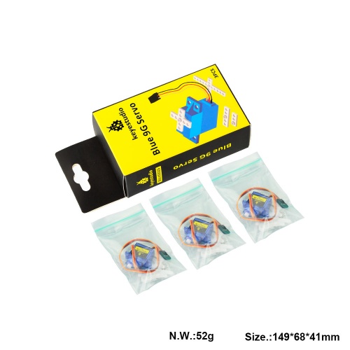
- Keyestudio Blue 9G Servo x 3pcs
Resources
Get One Now
- Official website: http://www.keyestudio.com/ks0326.html
