Ks0193 keyestudio Self-balancing Car
Overview
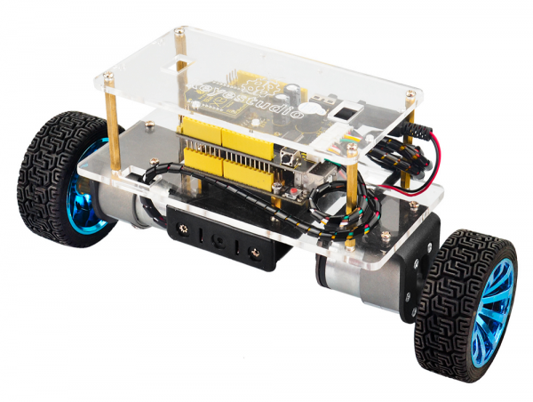
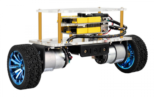
How to DIY a mini balance car on your own? This balance car kit is based on Arduino development platform. We mainly use UNO R3 as core and balance shield with built-in MPU-6050 as drive board to test the car body posture.
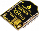
The balance shield comes with a Bluetooth interface, fully compatible with the Bluetooth XBee module (only compatible with Andriod system).
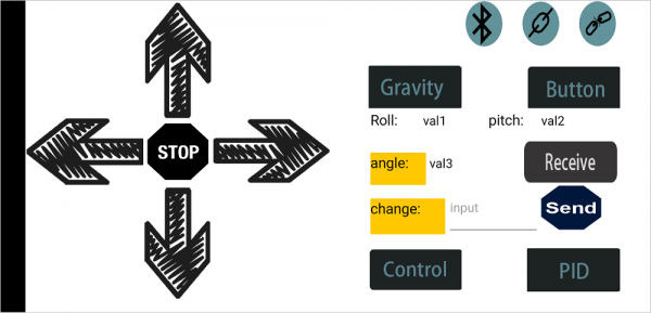
When connecting to Bluetooth, you can easily control the moving direction of balance car with Bluetooth APP, making a variety of unique postures.
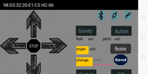
To facilitate the operation control, Bluetooth APP has both key and gravity control modes.
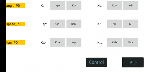
Moreover, it adds the function of adjusting the balance angle and PID parameters as well, so you can perfectly adjust and control the balance car.
No need to worry how to play it. We can provide you with all assembly components, as well as the corresponding installation, debugging method and program.
Operation Principle
The self-balancing car uses the power of the car body to maintain the relative balance, which is a process of dynamic balance.
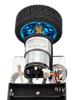
The power to maintain the balance of the car comes from the movement of the wheels, driven by two DC motors.
The control of the car body can be divided into three control tasks as follows:
- 1. Balance Control: keep the car upright and balanced by controlling the forward and backward rotation of the car’s wheel.
- 2. Speed Control: realize the front and rear movement and speed control by controlling the inclination of the car. In fact, it is achieved finally by controlling the speed of the motor.
- 3. Direction Control: realize the steering control by controlling the rotational speed differences between the two motors of the car.
In this way, it is relatively simple to understand the three control tasks.
But in the final control process, it comes down to the control of a control quantity. So there will be coupling between the three tasks, which will interfere with each other.
The key is to control the car’s balance; the speed and direction control should be as smooth as possible.
Parameters of balance car
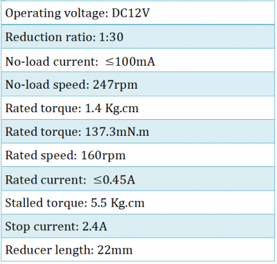
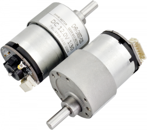
- 1.Motor parameters:
- 2.Working voltage: DC 9-12V
- 3.Motor drive chip: TB6612FNG
- 4.Body posture detection: MPU-6050
- 5.Comes with power control switch
- 6.Comes with Bluetooth control switch for controlling serial communication
Pay special attention to:
The balance shield comes with a slide switch for controlling the Bluetooth communication.
When upload the source code, must turn the slide switch OFF; otherwise, code uploading will fail.
When connecting to the Bluetooth module, should turn the slide switch ON.
Kit List
The kit packaging contains all electronic components for this self-balancing car. As you work your way through each project, you will learn how to control the car.
Assembly Steps
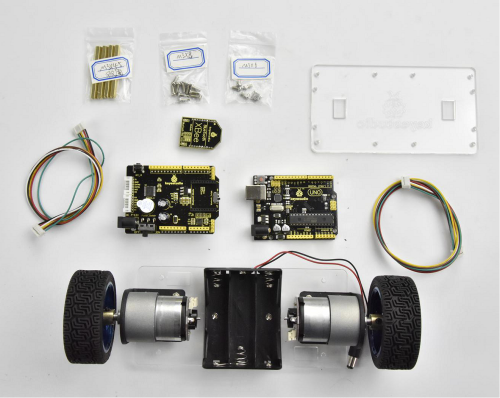
(1) Prepare all the components shown below.
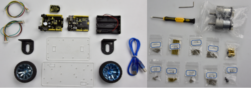
(2) To begin with, we start to install the bottom Acrylic plate.
Find out the parts below:
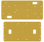
- Bottom Acrylic plate
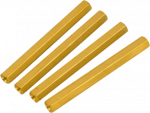
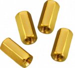
- Dual-pass M3*10MM hex copper pillar x 4pcs
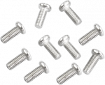
- M3*8MM screw x 4pcs
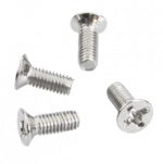
- M3*12MM flat head screw x 2pcs
- M3 nickel plating nut x 2pcs
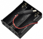
- Battery case
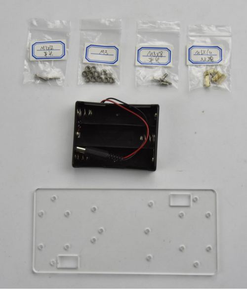
We are now going to mount the battery case and copper pillars on the Acrylic plate.
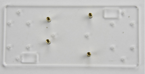
Fix the 4pcs M3*10MM copper pillar onto the Acrylic plate using 4pcs M3*8MM screws.
Then Mount the battery case on the Acrylic plate using 2pcs M3*12MM flat head screws and 2pcs M3 nickel plating Nuts.

(3) Next, move on to install the motor and wheel onto bottom Acrylic plate.
Find out the parts below:
- Bottom Acrylic plate mounted with battery case
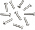
- M3*12MM round-head screw x 8pcs
- M3 nickel plating nut x 8pcs
- M4*6MM black screw x 2pcs
- Two wheels
- Two black connectors
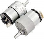
- Two motors
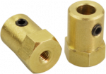
- Two copper hex couplers
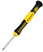
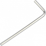
- M2 wrench Type L
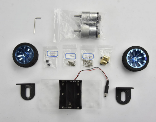
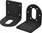
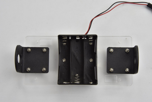
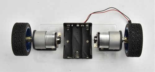
Go to mount the two black connectors onto the Acrylic plate using 8pcs M3*12MM round-head screws and 8pcs M3 nickel plating nuts. Shown below.
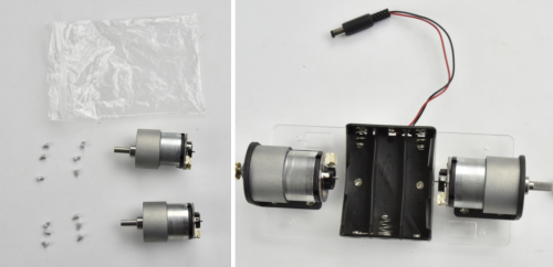
Each motor is equipped with six screws in the bag. Go to mount the two motors on the black connectors using the screws.
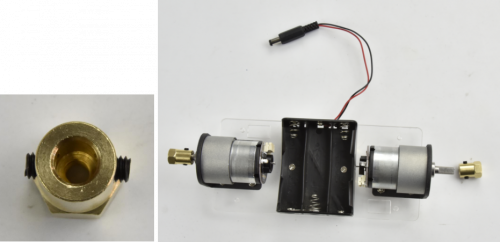
Screw each copper hex couplers with two screws. Then fix the two copper couplers on the two motors using a wrench.
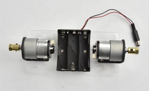
Finally mount the two wheels to the two hex copper couplers using 2pcs M4*6MM black screws.
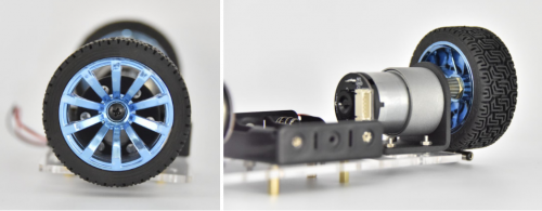
Up to now, the bottom motor wheel are installed well!
(4) The final step is to install the control board and the top Acrylic plate.
- Top Acrylic plate
- UNO R3 control board
- keyestudio balance shield
- Bluetooth XBee module HC-06
- M3*6MM round-head screw x 3pcs
- M3*45MM copper pillar x 4pcs
- M3*8MM round-head screw x 8pcs
- 6pin 30CM connector wire x 2pcs
Go to screw the UNO R3 control board onto the 4pcs M3*10MM copper pillars mounted on the Acrylic plate with 3pcs M3*6MM round-head screws.
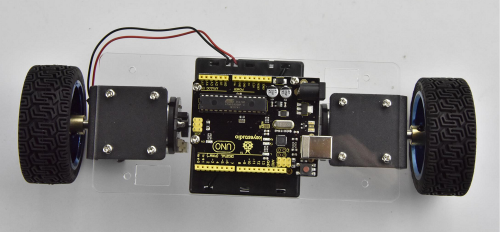
Then stack the keyestudio balance shield onto UNO R3 control board. And plug the Bluetooth XBee module HC-06 into the balance shield.
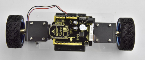
Go to connect the motor to the balance shield using 6pin PH2.0 30CM connector wire. Simply connect the motor to the nearest motor connector.
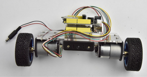
After that, screw the 4pcs M3*45MM copper pillars on the Acrylic plate with 4pcs M3*8MM round head screws. And connect well the battery plug to DC black jack of UNO R3.
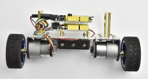
The back view is showed below:
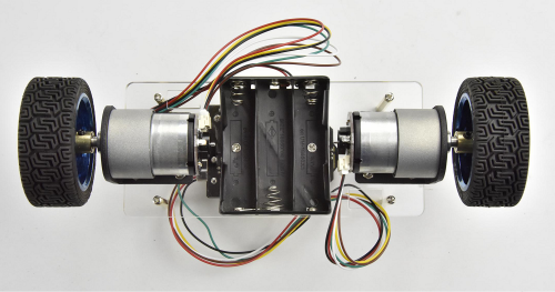
The final part is to install the top Acrylic plate onto the 4pcs M3*45MM copper pillars with 4pcs M3*8MM round-head screws.
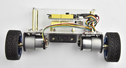
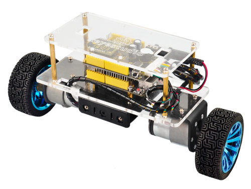
Congrats! The balance car is installed well.
Project 1: Getting Started with Main Board and ARDUINO
The UNO Control Board
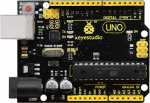
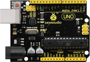
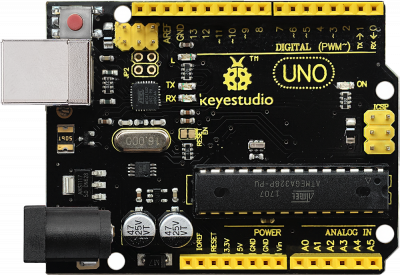
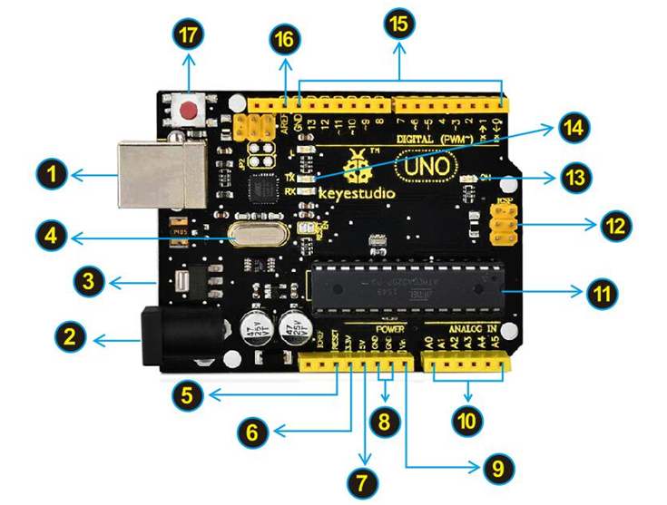
When it comes to using the UNO R3 as core of our robot, the UNO is the best board to get started with electronics and coding. If this is your first experience tinkering with the platform, the UNO is the most robust board you can start playing with.
Well, let's at first have a look at this UNO R3 board.
The Balance Car Shield
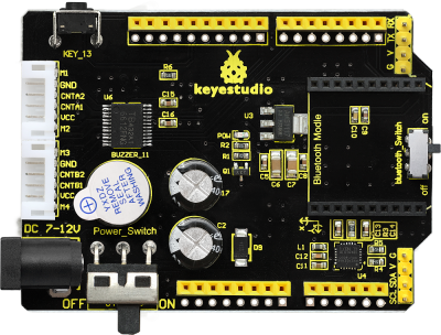
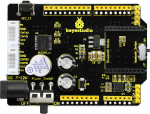
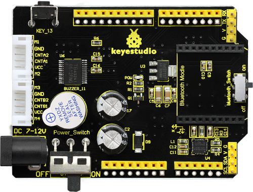
The balance shield is an important part for this balance car. With it, you can DIY the balance car more simple.
It is fully compatible with UNO R3 board; just stack it onto the control board.
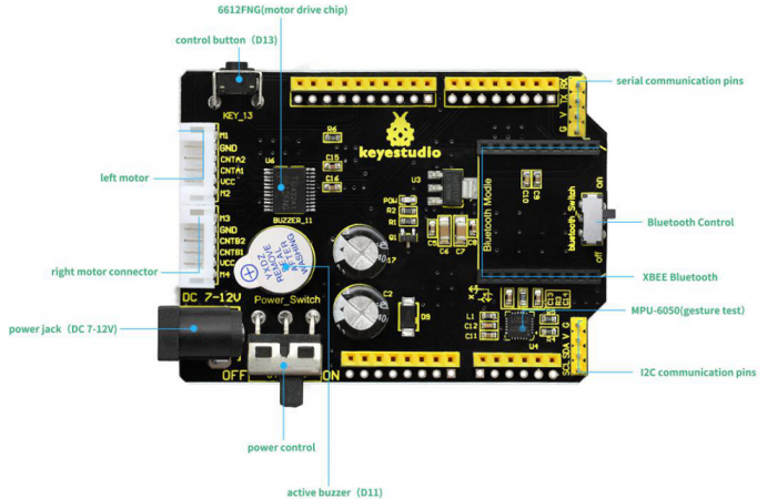
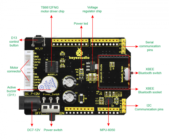
The balance shield comes with a 6612FNG chip for driving two DC motors; two white connectors for connecting DC motor; a DC power jack for powering on the shield and UNO R3;
Also comes with a large slide switch for controlling the power switch; a MPU-6050 for testing the posture; a XBEE Bluetooth interface for connecting Bluetooth module to communicate with Andriod devices; a small slide switch for controlling Bluetooth module’s communication; also comes with a button and an active buzzer.
The control pins of UNO R3 are all brought out as female header on the shield; the serial port and I2C communication pins are brought out as pin headers.
Note: connect the motor to the motor’s connector on the shield.

Installing Arduino IDE
When you get the UNO development board, first you should install the software and driver of Arduino. You can see all the Arduino software versions from the link below:
https://www.arduino.cc/en/Main/OldSoftwareReleases#1.5.x
Or you can browse the ARDUINO website at this link, https://www.arduino.cc, pop up the following interface.
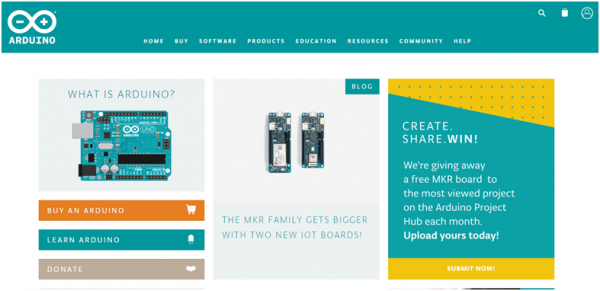
Then click the SOFTWARE on the browse bar, you will have two options ONLINE TOOLS and DOWNLOADS.
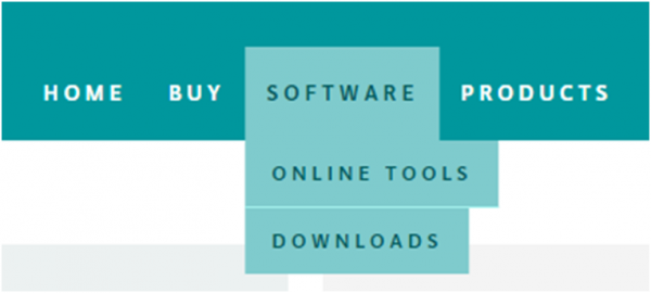
Click DOWNLOADS, it will appear the latest software version of ARDUINO 1.8.5 shown as below.
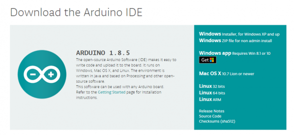
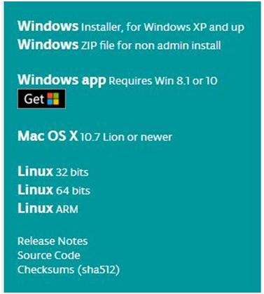
In this software page, on the right side you can see the version of development software for different operating systems. So ARDUINO has a rather powerful compatibility. You should download the software that is compatible with the operating system of your computer.
In our project, we will take WINDOWS system as an example here. There are also two options under Windows system, one is installed version, the other is non-installed version.
For simple installed version, first click Windows Installer, you will get the following page.

This way you just need to click JUST DOWNLOAD, then click the downloaded file to install it.
For non-installed version, first click Windows ZIP file, you will also get the pop-up interface as the above figure.
Click JUST DOWNLOAD, and when the ZIP file is downloaded well to your computer, you can directly unzip the file and then click the icon of ARDUINO program to start it.
Installing Arduino (Windows)
Install Arduino with the exe. Installation package
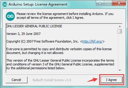
Click“I Agree”to see the following interface.
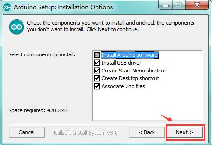
Click “Next”. Pop up the interface below.
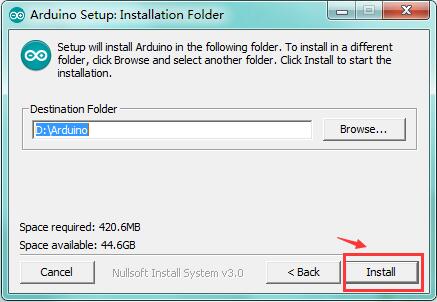
You can press Browse… to choose an installation path or directly type in the directory you want.
Then click “Install” to initiate installation.
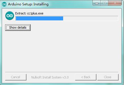
Wait for the installing process, if appear the interface of Window Security, just continue to click Install to finish the installation.
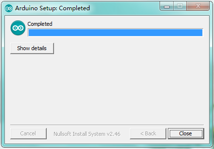
All right, up to now, you have completed the Arduino setup! The following icon will appear on your PC desktop.
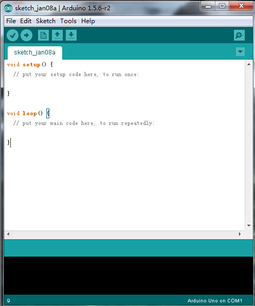
Double-click the icon of Arduino to enter the desired development environment shown as below.
Installing Driver
Next, we will introduce the driver installation of UNO R3 development board. The driver installation may have slight differences in different computer systems. So in the following let’s move on to the driver installation in the WIN 7 system.
The Arduino folder contains both the Arduino program itself and the drivers that allow the Arduino to be connected to your computer by a USB cable. Before we launch the Arduino software, you are going to install the USB drivers.
Plug one end of your USB cable into the Arduino and the other into a USB socket on your computer.
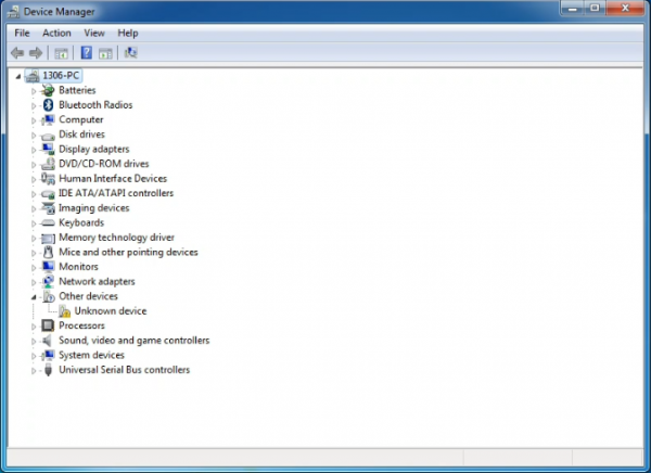
When you connect UNO board to your computer at the first time, right click the icon of your “Computer” —>for “Properties”—> click the “Device manager”, under “Other Devices”, you should see an icon for“Unknown device” with a little yellow warning triangle next to it. This is your Arduino.
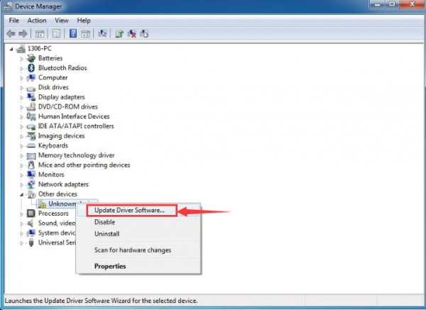
Then right-click on the device and select the top menu option (Update Driver Software...) shown as the figure below..
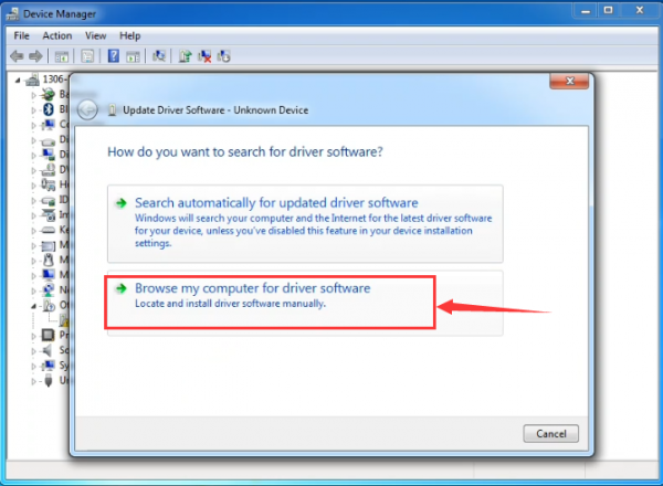
It will then be prompted to either “Search Automatically for updated driversoftware” or “Browse my computer for driver software”. Shown as below. In this page, select “Browse my computer for driver software”.
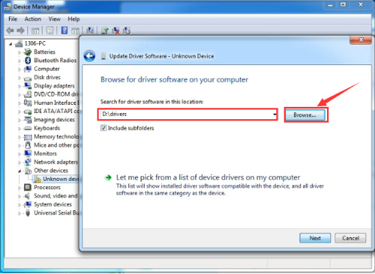
After that, select the option to browseand navigate to the “drivers” folder of Arduino installation.
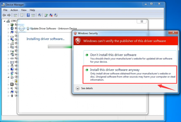
Click “Next” and you may get a security warning, if so, allow the software to be installed. Shown as below.
Once the software has been installed, you will get a confirmation message. Installation completed, click “Close”.
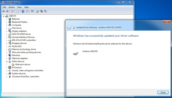
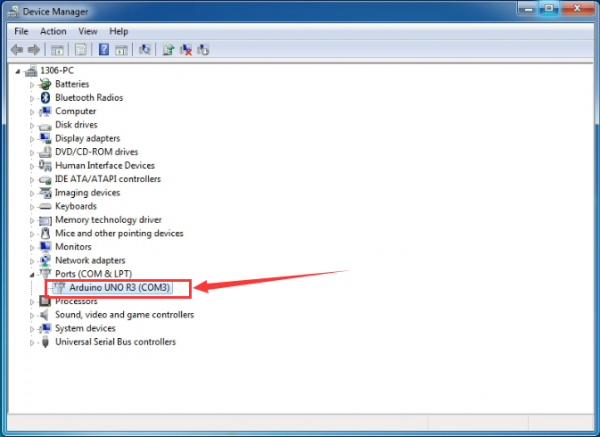
Up to now, the driver is installed well. Then you can right click “Computer” —>“Properties”—>“Device manager”, you should see the device as the figure shown below.
Example Use of ARDUINO IDE
STEP 1: Open Arduino
In the previous, we have introduced the driver installation of UNO R3 development board. So this time let’s first have basic understanding of the development environment of ARDUINO. After that, you will learn how to upload the program to Arduino board.
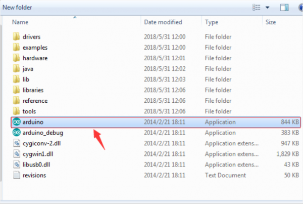
First of all, open the unzipped folder of ARDUINO development software and click icon of ARDUINO to open the software, as the figure shown below.
STEP 2: Build Projects
When open the Arduino software, you will have two options as below:
- Build a new project
- Open an exiting project example
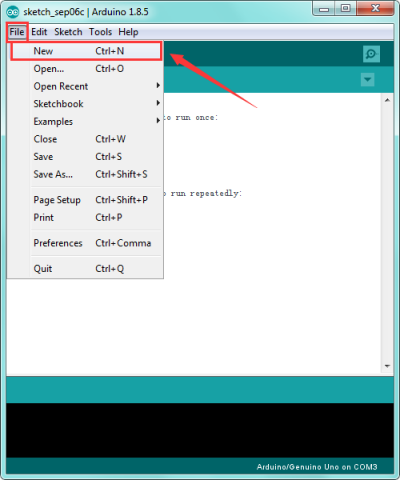
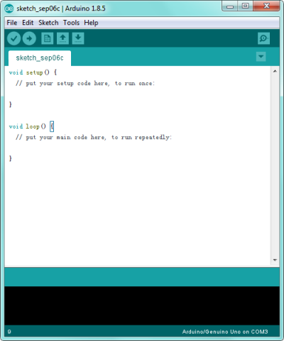
If you want to build a new project, please select “File”→then click “New”, you will see the software interface as follows.
![]()
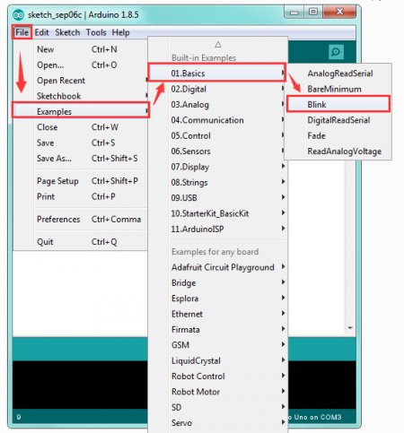
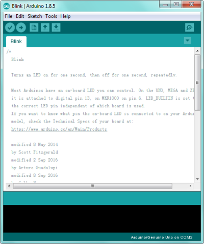
If you want to open an example project, please select File→Example→Basics→Blink. Shown below.
![]()
STEP 3: Select Arduino Board
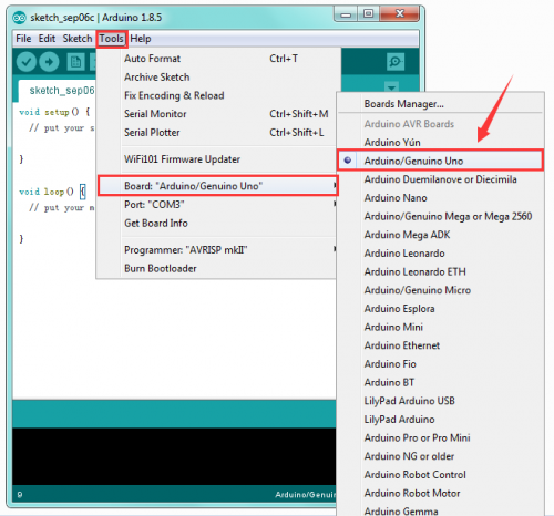
On the Arduino software, you should click Tools→Board , select the correct board. Here in our tutorial we should select Arduino Uno. Shown as below.
STEP 4: Select Serial Port
If you are not sure which port is correct, at first directly open the Control Panel of your computer, then click to open Device Manager, you can check the COM port here. Shown as below.

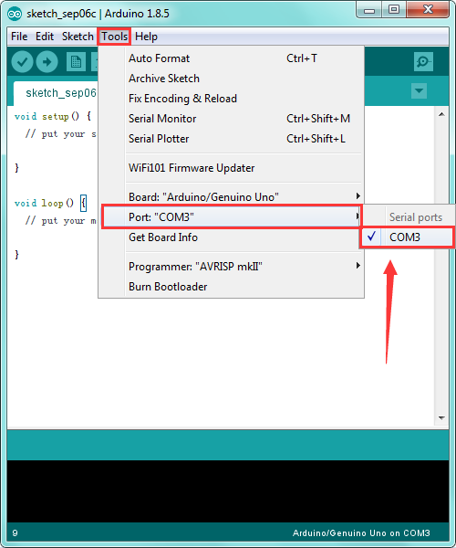
Then you should click Tools→Serial Port. It may be COM3 or higher (COM1 and COM2 are usually reserved as hardware serial port).
STEP 5: Upload the Code to Your Board
Before showing you how to upload the code to your board, first of all let me introduce the function of each icon on the Tool bar of Arduino IDE. Look at the picture showed below.
![]()
Project 2: Button and Buzzer
Description:
In the previous project, you have learned how to use Arduino software environment.
Want to try it? Great. This project let’s get started with a basic program to enter the programming world of arduino.
The keyestudio balance car shield comes with a button KEY_13 and an active buzzer. To be specific, button is controlled by pin D13 on UNO R3; active buzzer is controlled by pin D11 on UNO R3.

In the experiment, we get down to controlling the buzzer with button. When press the button, the buzzer will sound.
The active buzzer comes with oscillating circuit. Actually, simple to set the pin D11 to HIGH, the buzzer can beep. We come to simulate the setting method of passive buzzer. Set different square wave to make the active buzzer output different sounds.
Source Code:
const int buz = 11;    // set the buzzer pin
const int btn = 13;    //set the button pin
int button;    //button variable

void setup()
{
  pinMode(btn,INPUT);       //set to INPUT state
  pinMode(buz,OUTPUT);       //set to OUTPUT state
}

void loop()
{
  button = digitalRead(btn);       //assign the button value to variable button
  if(button == 0)    //if press the button
  {
    delay(10);    //delay time
    if(button == 0)     //judge again, if the button is pressed
    {
      buzzer();  // execute the subfunction of buzzer
    }
  }
  else        // button not pressed
  {
    digitalWrite(buz,LOW);    // buzzer not sounds
  }
}

//buzzer makes tick sound
void buzzer()
{
    for(int i=0;i<50;i++)
    {
    digitalWrite(buz,HIGH);
    delay(1);
    digitalWrite(buz,LOW);
    delay(1);
    }
    delay(50);
    for(int i=0;i<50;i++)
    {
    digitalWrite(buz,HIGH);
    delay(1);
    digitalWrite(buz,LOW);
    delay(1);
    }
}
Test Result:
Installed well the balance car, upload the source code and power on; turn the slide switch ON and then press the KEY_13 button on the shield.
The active buzzer on the balance shield will sound; otherwise, it will not sound.

Project 3: TB6612 Motor Driving
Description:
We have tested the balance shield’s button and buzzer. Now, we are going to mainly test the motor driving ability.
In the project, we control the right motor’s direction by pin D8 D12 on UNO R3; speed is controlled by pin D10. The left motor’s direction by pin D7 D6 on UNO R3; speed is controlled by pin D9.
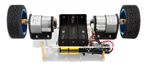
The specified control method refers to the table below:

The D9 D10 are PWM pins, which can be used as Digital output or Analog output.
If used as Analog output, it needs to call the analogWrite() function of ARDUINO, and this analogWrite() function can be controlled in the range of 0-255.
A call to analogWrite() is on a scale of 0-255, such that analogWrite(255) requests a 100% duty cycle (always on), and analogWrite(127) is a 50% duty cycle (on half the time).
In the code, the greater the PWM value set by pin D9 and D10, the faster the two motors’ speed.
In the following, we only simply set the two motors to turn forward and backward.
Source Code:
//TB6612 pins
const int right_R1=8;
const int right_R2=12;
const int PWM_R=10;
const int left_L1=7;
const int left_L2=6;
const int PWM_L=9;

void setup()
{
  Serial.begin(9600);          //set the baud rate to 9600

  pinMode(right_R1,OUTPUT);     // set all TB6612pins to OUTPUT
  pinMode(right_R2,OUTPUT);
  pinMode(PWM_R,OUTPUT);
  pinMode(left_L1,OUTPUT);
  pinMode(left_L2,OUTPUT);
  pinMode(PWM_L,OUTPUT);
}

void loop()
{
  // two motors turn forward
  digitalWrite(right_R1,HIGH);
  digitalWrite(right_R2,LOW);
  digitalWrite(left_L1,HIGH);
  digitalWrite(left_L2,LOW);
  analogWrite(PWM_R,100);   // write into PWM value 0~255(speed)
  analogWrite(PWM_L,100);
}
Test Result:
Installed well the balance car, upload the source code and power on; turn the slide switch ON.
Both left and right motors start to turn forward.

Project 4: Hall Encoder Test
Description:
We have introduced how to set the speed of right and left motor by PWM value of D9 D10.
But how to get the specified speed? Well, we can test it using the motor’s built-in Hall encoder.
In this project, you will learn how to calculate the specified speed by the number of pulses got from Hall encoder within 100ms.
Source Code:
//TB6612 pins
const int right_R1=8;
const int right_R2=12;
const int PWM_R=10;
const int left_L1=7;
const int left_L2=6;
const int PWM_L=9;

const int PinA_left = 5;    // set the left motor’s pulse pin to D5
const int PinA_right = 4;    //set the right motor’s pulse pin to D4

int times=0,newtime=0,d_time=100;   // time, new time, time interval
int valA=0,valB=0,flagA=0,flagB=0;    //variable valA and valB for calculating the number of pulse

void setup()
{
  Serial.begin(9600);

  pinMode(right_R1,OUTPUT);    // set the TB6612 pins to OUTPUT
  pinMode(right_R2,OUTPUT);
  pinMode(PWM_R,OUTPUT);
  pinMode(left_L1,OUTPUT);
  pinMode(left_L2,OUTPUT);
  pinMode(PWM_L,OUTPUT);

  pinMode(PinA_left,INPUT);    // set the pulse pin to INPUT
  pinMode(PinA_right,INPUT);

}

void loop()
{
  //both motors turn forward
  digitalWrite(right_R1,HIGH);
  digitalWrite(right_R2,LOW);
  digitalWrite(left_L1,HIGH);
  digitalWrite(left_L2,LOW);
  analogWrite(PWM_R,100);   //write into PWM value 0~255(speed)
  analogWrite(PWM_L,200);

  newtime=times=millis();     //make newtime and times equal to the time the program runs to here
  while((newtime-times)<d_time)    //if less than the setting d_time,always loop
  {
    if(digitalRead(PinA_left)==HIGH&&flagA==0)   // if detects HIGH
    {
      valA++;      //valA plus 1
      flagA=1;
    }
    if(digitalRead(PinA_left)==LOW&&flagA==1)    // if LOW
    {
      valA++;     //valA plus 1
      flagA=0;
    }

    if(digitalRead(PinA_right)==HIGH&&flagB==0)
    {
      valB++;
      flagB=1;
    }
    if(digitalRead(PinA_right)==LOW&&flagB==1)
    {
      valB++;
      flagB=0;
    }
    newtime=millis();        //newtime equals to the time the program runs to here
  }
  Serial.println(valA);      // print out the value of valA and B
  Serial.println(valB);
  valA=valB=0;             //set to 0
}
Test Result:
Installed well the balance car, upload the source code and power on; turn the slide switch ON.
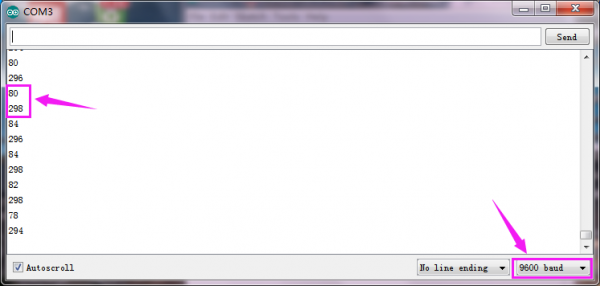
Then open the Arduino IDE, set the baud rate to 9600, the serial monitor will pop up the number of pulse got from Hall encoder within 100ms ( correspond to left and right motor).
See the figure below.
Project 5: Internal Timer Interrupt
Description:
In previous section, you have learned how to get the number of pulses by Hall encoder of motor within 100ms.
Now, we will use the built-in internal timer (timer2) of UNO R3 board. Calculate out the specified speed by the number of pulses got from Hall encoder within 100ms.
Source Code:
Before test the source code, do remember to add the corresponding library.
You can refer to the method in the link below:
https://wiki.keyestudio.com/How_to_Install_Arduino_Library
#include <MsTimer2.h>

//TB6612 pins
const int right_R1=8;
const int right_R2=12;
const int PWM_R=10;
const int left_L1=7;
const int left_L2=6;
const int PWM_L=9;

const int PinA_left = 5;        //set the left motor’s pulse pin to D5
const int PinA_right = 4;       //set the right motor’s pulse pin to D4

int times=0,newtime=0,d_time=100;   // time, new time, time interval
int valA=0,valB=0,flagA=0,flagB=0;   //variable valA and valB for calculating the number of pulse

void setup()
{
  Serial.begin(9600);

  pinMode(right_R1,OUTPUT);     //set the TB6612 pins to OUTPUT
  pinMode(right_R2,OUTPUT);
  pinMode(PWM_R,OUTPUT);
  pinMode(left_L1,OUTPUT);
  pinMode(left_L2,OUTPUT);
  pinMode(PWM_L,OUTPUT);

  pinMode(PinA_left,INPUT);      // set the pulse pin to INPUT
  pinMode(PinA_right,INPUT);

  MsTimer2::set(100, inter); // trigger an interrupt per 100ms
  MsTimer2::start();    // start interrupt
}

void loop()
{
  //both motors turn forward
  digitalWrite(right_R1,HIGH);
  digitalWrite(right_R2,LOW);
  digitalWrite(left_L1,HIGH);
  digitalWrite(left_L2,LOW);
  analogWrite(PWM_R,100);    //write into PWM value 0~255(speed)
  analogWrite(PWM_L,200);

  if(digitalRead(PinA_left)==HIGH&&flagA==0)     // calculate the pulse value
    {
      valA++;
      flagA=1;
    }
    if(digitalRead(PinA_left)==LOW&&flagA==1)
    {
      valA++;
      flagA=0;
    }

    if(digitalRead(PinA_right)==HIGH&&flagB==0)
    {
      valB++;
      flagB=1;
    }
    if(digitalRead(PinA_right)==LOW&&flagB==1)
    {
      valB++;
      flagB=0;
    }

}

//interrupt function
void inter()
{
    sei();    //allow whole interrupts
    Serial.print("valA = ");     //print out the pulse value on serial monitor
    Serial.println(valA);
    Serial.print("valB = ");
    Serial.println(valB);
    valA = valB = 0;
}
Test Result
Installed well the balance car, power on and upload the source code to the board;
Turn the slide switch ON.
Then open the monitor of Arduino IDE, set the baud rate to 9600.
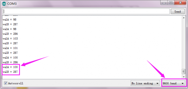
The serial monitor will pop up the number of pulse got from Hall encoder within 100ms ( correspond to left and right motor).
See the figure below.
Project 6: Bluetooth Test
Description:
The kit contains a Bluetooth XBee module, which is compatible with Andriod system.
Keyestudio Bluetooth XBee wireless module HC-06 has features of compact size, compatible with XBEE shield, and suitable for various 3.3V MCU systems. It also comes with efficient on-board antenna.
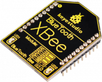
More contents check the link here.
https://wiki.keyestudio.com/Ks0144_keyestudio_XBee_Bluetooth_Wireless_Module_HC-06
In this project, go to learn how to use Bluetooth APP to make the balance car communicate with Andriod Bluetooth. You are able to use Bluetooth APP to randomly control the balance car move.
Note:
The keyestudio balance shield comes with a slide switch for controlling the Bluetooth communication.
When upload the source code, must turn the switch OFF; or else code uploading fails.
When connect to the Bluetooth module, should turn the switch ON.
How to use Bluetooth APP?
- Installed the balance car, upload the source code and power on; turn the power switch ON; turn the Bluetooth switch ON.
- Install the Bluetooth APP, then you can see the icon below on your phone.
Click the link below to download the APP:
https://drive.google.com/open?id=1L69xdfmOvfhg0Wjh_p2FrtRkhs1h0fEu
- Tap to open the Bluetooth APP; you will see the interface shown below.
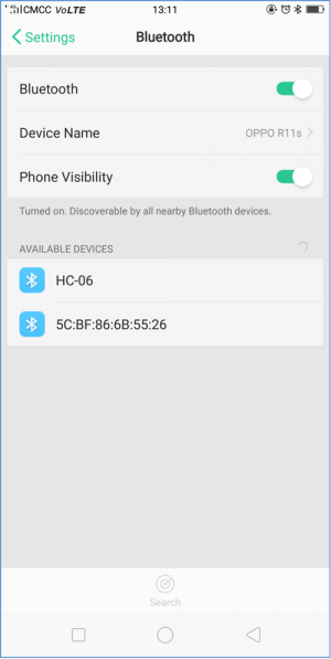
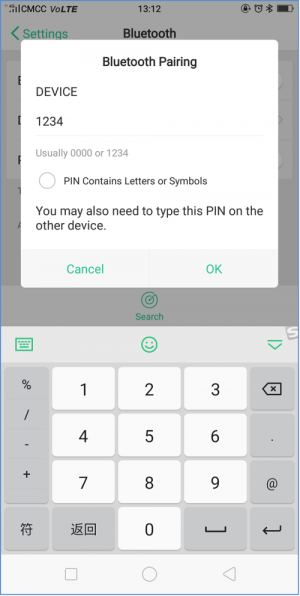
- Tap the HC-06 (search at the first time is a address, so tap the address); the PIN is 1234.
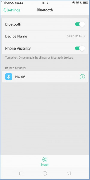
- Finally you will see the paired device.
tap the key ![]() , the two motors of balance car stop;
, the two motors of balance car stop;
tap the key  , the two motors of balance car turn backward.
Source Code:
//TB6612 pins
const int right_R1=8;
const int right_R2=12;
const int PWM_R=10;
const int left_L1=7;
const int left_L2=6;
const int PWM_L=9;
char val;   // Bluetooth variable

void setup()
{
  Serial.begin(9600);

  pinMode(right_R1,OUTPUT);   //set TB6612 pins OUTPUT
  pinMode(right_R2,OUTPUT);
  pinMode(PWM_R,OUTPUT);
  pinMode(left_L1,OUTPUT);
  pinMode(left_L2,OUTPUT);
  pinMode(PWM_L,OUTPUT);
}

void loop()
{
  if(Serial.available())    //if serial buffer value is available
  {
    val = Serial.read();      //assign the value read from serial port to val
    Serial.println(val);
    switch(val)             //switch statement
    {
      case 'F': front(); break;     //motor turns front
      case 'B': back(); break;       //turn back
      case 'S': Stop();break;    //stop
    }
  }
}

//turn front
void front()
{
  digitalWrite(right_R1,HIGH);
  digitalWrite(right_R2,LOW);
  digitalWrite(left_L1,HIGH);
  digitalWrite(left_L2,LOW);
  analogWrite(PWM_R,100);
  analogWrite(PWM_L,100);
}
//turn back
void back()
{
  digitalWrite(right_R1,LOW);
  digitalWrite(right_R2,HIGH);
  digitalWrite(left_L1,LOW);
  digitalWrite(left_L2,HIGH);
  analogWrite(PWM_R,100);
  analogWrite(PWM_L,100);
}
//stop
void Stop()
{
  digitalWrite(right_R1,LOW);
  digitalWrite(right_R2,HIGH);
  digitalWrite(left_L1,LOW);
  digitalWrite(left_L2,HIGH);
  analogWrite(PWM_R,0);
  analogWrite(PWM_L,0);
}
Project 7: MPU6050 Test
Description:
When DIY the balance car, should obtain its posture at first. The most used is through accelerometer and gyroscope.
In theory, only need two-axis accelerometer (Z-axis in the straight direction and the Y-axis along the moving direction of the car) and a single-axis gyroscope (the angular velocity in the X-axis direction of the car wheel are calculated).
In this project, we use the built-in MPU-6050 chip of keyestudio balance shield to test the data of the three-axis accelerometer and the three-axis gyroscope, printing out it on the serial monitor.
The acceleration range is +-2g; the gyroscope range is +-250°/S.
Source Code:
#include <Wire.h>

long accelX, accelY, accelZ;      // set to overall variable; can be used directly inside the function.
float gForceX, gForceY, gForceZ;

long gyroX, gyroY, gyroZ;
float rotX, rotY, rotZ;

void setup() {
  Serial.begin(9600);
  Wire.begin();
  setupMPU();
}

void loop() {
  recordAccelRegisters();
  recordGyroRegisters();
  printData();
  delay(100);
}

void setupMPU(){
  // REGISTER 0x6B/REGISTER 107:Power Management 1
  Wire.beginTransmission(0b1101000); //This is the I2C address of the MPU (b1101000/b1101001 for AC0 low/high datasheet Sec. 9.2)
  Wire.write(0x6B); //Accessing the register 6B/107 - Power Management (Sec. 4.30)
  Wire.write(0b00000000); //Setting SLEEP register to 0, using the internal 8 Mhz oscillator
  Wire.endTransmission();

  // REGISTER 0x1b/REGISTER 27:Gyroscope Configuration
  Wire.beginTransmission(0b1101000); //I2C address of the MPU
  Wire.write(0x1B); //Accessing the register 1B - Gyroscope Configuration (Sec. 4.4)
  Wire.write(0x00000000); //Setting the gyro to full scale +/- 250deg./s (转化为rpm:250/360 * 60 = 41.67rpm) ;The highest can be converted to 2000deg./s
  Wire.endTransmission();

  // REGISTER 0x1C/REGISTER 28:ACCELEROMETER CONFIGURATION
  Wire.beginTransmission(0b1101000); //I2C address of the MPU
  Wire.write(0x1C); //Accessing the register 1C - Acccelerometer Configuration (Sec. 4.5)
  Wire.write(0b00000000); //Setting the accel to +/- 2g(if choose +/- 16g,the value would be 0b00011000)
  Wire.endTransmission();
}

void recordAccelRegisters() {
  // REGISTER 0x3B~0x40/REGISTER 59~64
  Wire.beginTransmission(0b1101000); //I2C address of the MPU
  Wire.write(0x3B); //Starting register for Accel Readings
  Wire.endTransmission();
  Wire.requestFrom(0b1101000,6); //Request Accel Registers (3B - 40)

  // Use left shift << and bit operations |  Wire.read() read once 1bytes,and automatically read the data of the next address on the next call.
  while(Wire.available() < 6);  // Waiting for all the 6 bytes data to be sent from the slave machine (Must wait for all data to be stored in the buffer before reading)
  accelX = Wire.read()<<8|Wire.read(); //Store first two bytes into accelX (Automatically stored as a defined long value)
  accelY = Wire.read()<<8|Wire.read(); //Store middle two bytes into accelY
  accelZ = Wire.read()<<8|Wire.read(); //Store last two bytes into accelZ
  processAccelData();
}

void processAccelData(){
  gForceX = accelX / 16384.0;     //float = long / float
  gForceY = accelY / 16384.0;
  gForceZ = accelZ / 16384.0;
}

void recordGyroRegisters()
{
  // REGISTER 0x43~0x48/REGISTER 67~72
  Wire.beginTransmission(0b1101000); //I2C address of the MPU
  Wire.write(0x43); //Starting register for Gyro Readings
  Wire.endTransmission();
  Wire.requestFrom(0b1101000,6); //Request Gyro Registers (43 ~ 48)
  while(Wire.available() < 6);
  gyroX = Wire.read()<<8|Wire.read(); //Store first two bytes into accelX
  gyroY = Wire.read()<<8|Wire.read(); //Store middle two bytes into accelY
  gyroZ = Wire.read()<<8|Wire.read(); //Store last two bytes into accelZ
  processGyroData();
}

void processGyroData() {
  rotX = gyroX / 131.0;
  rotY = gyroY / 131.0;
  rotZ = gyroZ / 131.0;
}

void printData() {
  Serial.print("Gyro (deg)");
  Serial.print(" X=");
  Serial.print(rotX);
  Serial.print(" Y=");
  Serial.print(rotY);
  Serial.print(" Z=");
  Serial.print(rotZ);
  Serial.print(" Accel (g)");
  Serial.print(" X=");
  Serial.print(gForceX);
  Serial.print(" Y=");
  Serial.print(gForceY);
  Serial.print(" Z=");
  Serial.println(gForceZ);
}
