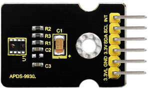
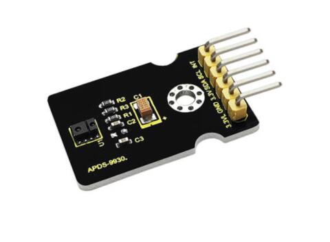
Ks0267 keyestudio APDS-9930 Attitude Sensor Module
Keyestudio APDS-9930 Attitude Sensor Module
Introduction
Keyestudio APDS-9930 attitude sensor module mainly uses APDS-9930 chip. APDS-9930 in a single 8 pin package can provide the ambient light sensor which is compatible with I2C interface and the infrared LED proximity sensor.
The ambient light sensor uses double light diode to approximate the visual response of low lumen human under 0.01 lux illumination, and its high sensitivity allows the device to operate in the dark glass.
The proximity sensor which is completely adjusted can detect 100 mm object, and exempt the factory calibration requirements of terminal equipment as well as sub-components. From the bright sunlight to the dark room, proximity sensor’s proximity detection function can operate well.
This module added micro optical lens can provide infrared energy efficient transmission and reception, which can reduce the overall power consumption. In addition, its internal state machine can make the device into a low power mode, bringing a very low average power consumption.
Performance Parameters
- Working Voltage:DC 3.3-3.8V
- Output Current:0-20mA
- Temperature Range:-40℃ to +85℃
Features
- Optical module integrated with ALS, infrared LED and proximity detector;
- Ambient Light Sensing,similar to the human eye’s visual response;
- Programmable interruption function with upper and lower thresholds;
- Up to 16-bit resolution;
- High sensitivity of operation in the back of dark glass;
- 0.01lux low lumen performance;
- Proximity detection, fully calibrated to 100 mm detection;
- Integrate infrared LED and synchronous LED driver;
- Eliminate factory calibration for proximity sensors;
- Programmable waiting timer, waiting state’s power consumption - 90μA (typical value);
- Programmable range is from 2.7 milliseconds to 8 seconds;
- Compatible with I2C interface, up to 400kHz (I2C fast mode);
- Dedicated interruption pin;
- Sleep mode power - 2.2μA (typical value).
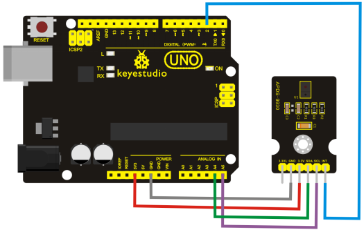
Connection Diagram
Sample Code
Libraries Download of Wire and APDS9930: [1]
- Hardware Connections:
IMPORTANT: The APDS-9960 can only accept 3.3V!
Arduino Pin APDS-9960 Board Function
3.3V - VCC - Power
GND - GND - Ground
A4 - SDA - I2C Data
A5 - SCL - I2C Clock
2 - INT - Interrupt
13 - - - LED
- Resources:
Include Wire.h and SparkFun_APDS-9960.h
Development environment specifics:
Written in Arduino 1.5.6
#include <Wire.h>
#include <SparkFun_APDS9960.h>

// Pins
#define APDS9960_INT    2  // Needs to be an interrupt pin
#define LED_PIN         13 // LED for showing interrupt

// Constants
#define LIGHT_INT_HIGH  1000 // High light level for interrupt
#define LIGHT_INT_LOW   10   // Low light level for interrupt

// Global variables
SparkFun_APDS9960 apds = SparkFun_APDS9960();
uint16_t ambient_light = 0;
uint16_t red_light = 0;
uint16_t green_light = 0;
uint16_t blue_light = 0;
int isr_flag = 0;
uint16_t threshold = 0;

void setup() {
  // Set LED as output
  pinMode(LED_PIN, OUTPUT);
  pinMode(APDS9960_INT, INPUT);
  // Initialize Serial port
  Serial.begin(9600);
  Serial.println();
  Serial.println(F("-------------------------------------"));
  Serial.println(F("SparkFun APDS-9960 - Light Interrupts"));
  Serial.println(F("-------------------------------------"));
  // Initialize interrupt service routine
  attachInterrupt(0, interruptRoutine, FALLING);
  // Initialize APDS-9960 (configure I2C and initial values)
  if ( apds.init() ) {
    Serial.println(F("APDS-9960 initialization complete"));
  } else {
    Serial.println(F("Something went wrong during APDS-9960 init!"));
  }
  // Set high and low interrupt thresholds
  if ( !apds.setLightIntLowThreshold(LIGHT_INT_LOW) ) {
    Serial.println(F("Error writing low threshold"));
  }
  if ( !apds.setLightIntHighThreshold(LIGHT_INT_HIGH) ) {
    Serial.println(F("Error writing high threshold"));
  }
  // Start running the APDS-9960 light sensor (no interrupts)
  if ( apds.enableLightSensor(false) ) {
    Serial.println(F("Light sensor is now running"));
  } else {
    Serial.println(F("Something went wrong during light sensor init!"));
  }
  // Read high and low interrupt thresholds
  if ( !apds.getLightIntLowThreshold(threshold) ) {
    Serial.println(F("Error reading low threshold"));
  } else {
    Serial.print(F("Low Threshold: "));
    Serial.println(threshold);
  }
  if ( !apds.getLightIntHighThreshold(threshold) ) {
    Serial.println(F("Error reading high threshold"));
  } else {
    Serial.print(F("High Threshold: "));
    Serial.println(threshold);
  }
  // Enable interrupts
  if ( !apds.setAmbientLightIntEnable(1) ) {
    Serial.println(F("Error enabling interrupts"));
  }
  // Wait for initialization and calibration to finish
  delay(500);
}
void loop() {
  // If interrupt occurs, print out the light levels
  if ( isr_flag == 1 ) {

    // Read the light levels (ambient, red, green, blue) and print
    if (  !apds.readAmbientLight(ambient_light) ||
          !apds.readRedLight(red_light) ||
          !apds.readGreenLight(green_light) ||
          !apds.readBlueLight(blue_light) ) {
      Serial.println("Error reading light values");
    } else {
      Serial.print("Interrupt! Ambient: ");
      Serial.print(ambient_light);
      Serial.print(" R: ");
      Serial.print(red_light);
      Serial.print(" G: ");
      Serial.print(green_light);
      Serial.print(" B: ");
      Serial.println(blue_light);
    }
    // Turn on LED for a half a second
    digitalWrite(LED_PIN, HIGH);
    delay(500);
    digitalWrite(LED_PIN, LOW);

    // Reset flag and clear APDS-9960 interrupt (IMPORTANT!)
    isr_flag = 0;
    if ( !apds.clearAmbientLightInt() ) {
      Serial.println("Error clearing interrupt");
    }
  }
}
void interruptRoutine() {
  isr_flag = 1;
}
Test Result
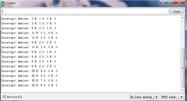
Wiring as the above diagram and burning the code, after powered-on, open the serial monitor, as the graph shown below.

Resources
- Libraries and Code Download:
https://fs.keyestudio.com/KS0267


