KS0501 Keyestudio MAX Kit
Note: If this MCU can't not be recognized by your computer. Don't be worried.
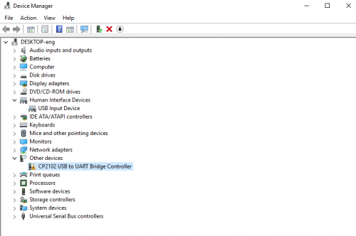
The USB-TTL chip on Max board adopts CP2102 serial chip. The driver program of this chip is included in Arduino 1.8 version and above, which is convenient. Plug on USB port of board, the computer can recognize the hardware and automatically install the driver of CP2102. If install unsuccessfully, or you intend to install manually, open the device manager of computer. Right click Computer----- Properties----- Device Manager.
Introduction
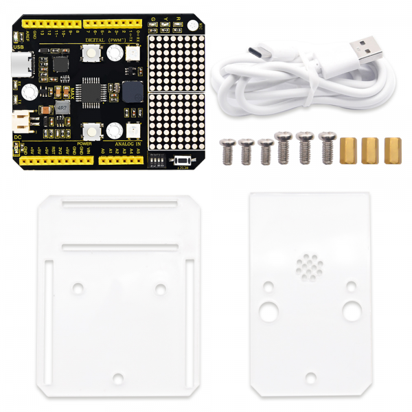
Keyestudio UNO MAX kit contains a Max development board, acrylic boards, screws, copper bushes and USB cable(With Type C port).
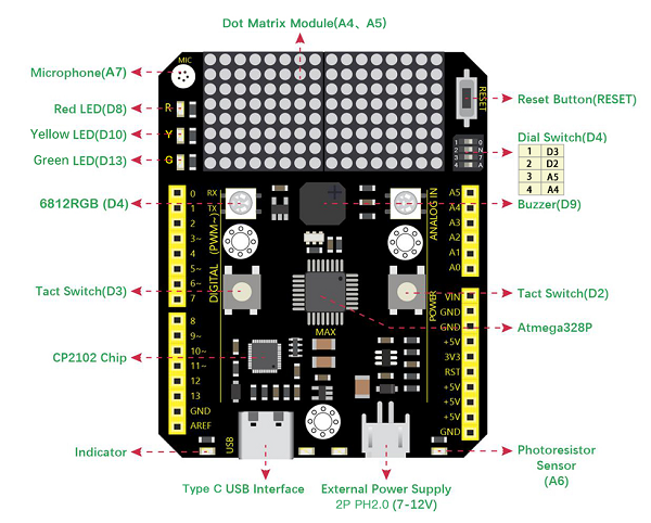
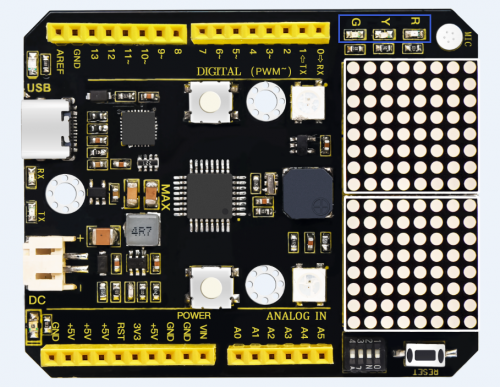
keyestudio Max development board is an Arduino uno-compatible board, which isbased on ATmega328P MCU, and with a cp2102 Chip as a UART-to-USB converter.MAX development board integrates three LEDs, two 6812RGB LEDs, two button switches, a buzzer, a microphone sensor, a light sensor, and an 8*16 dot matrix.
Using the onboard hardware, you can start 20 project courses. If you are a beginner, a MAX board is enough!
MAX can also be connected to all arduino sensors and modules, and it is also compatible with all arduino shield boards.
Now, use MAX to enter the magical world of ARDUINO!
Installing Max board Driver
Let’s install the driver of keyestudio Max board. The USB-TTL chip on Max board adopts CP2102 serial chip. The driver program of this chip is included in Arduino 1.8 version and above, which is convenient. Plug on USB port of board, the computer can recognize the hardware and automatically install the driver of CP2102.
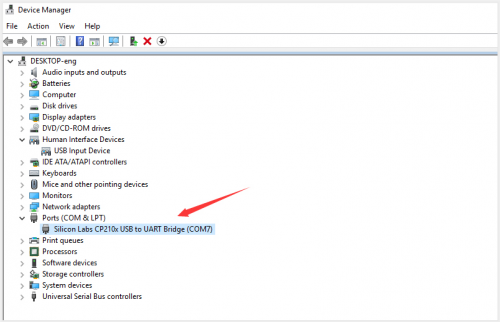
If install unsuccessfully, or you intend to install manually, open the device manager of computer. Right click Computer----- Properties----- Device Manager.
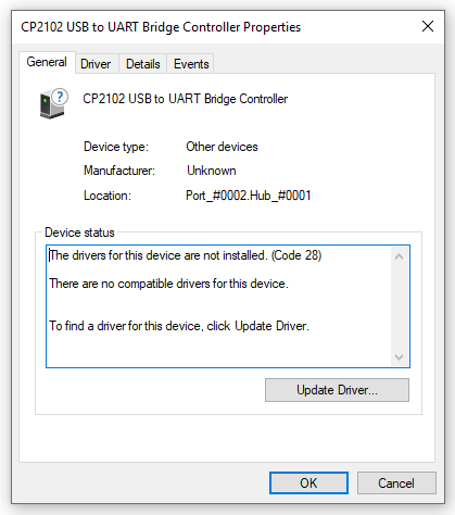
There is a yellow exclamation mark on the page, which implies installing unsuccessfully. Then we double click the hardware and update the driver.
Click “OK” to enter the following page, click“browse my computer for updated driver software”, find out the installed or downloaded ARDUINO software. As shown below:
We click “Browse”, then find out the driver folder, or you could enter “driver” to search in rectangular box, then click “next”, the driver will be installed successfully. (I place Arduino software folder on the desktop, you could follow my way)
Open device manager, we will find the yellow exclamation mark disappear. The driver of CP2102 is installed successfully.

Max development board Pinout
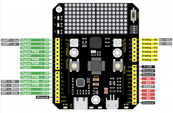
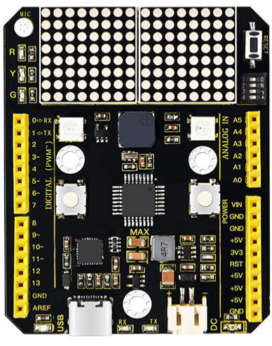
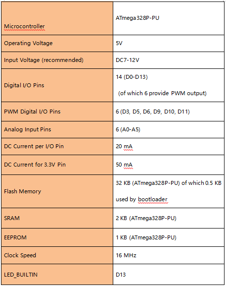
Max has 14 digital input/output pins (of which 6 can be used as PWM outputs), 6 analog inputs, a 16 MHz quartz crystal, a USB connection, a power jack, 2 ICSP headers and a reset button.
It contains everything needed to support the microcontroller; simply connect it to a computer with a USB cable or power it via an external DC power jack (DC 7-12V) or via female headers Vin/ GND(DC 7-12V) to get started.
Max development board onboard interface
- red LED: D8
- yellow LED: D10
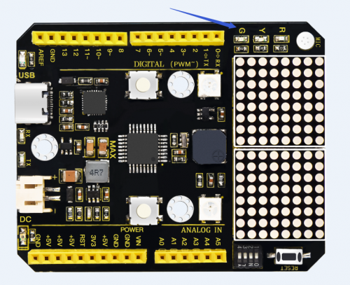
- green LED: D13
- 6812 RGB LED: D4
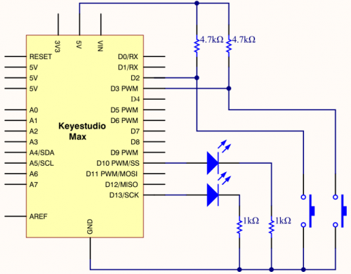
- two button switches: D2, D3
- buzzer: D9
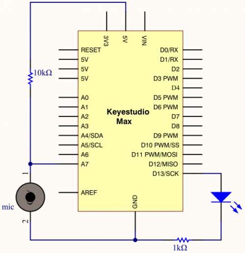
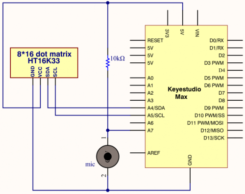
- microphone sensor: A7
- light sensor: A6
- 8*16 dot matrix:A4,A5 (I2C interface)
- 4-digit DIP switch: on right, D2, D3, A4, A5, these onboard components interface is connected. on left, these interface is disconnected,
- They are connected to the corresponding interface on the max board pin header.
Install Arduino software and Driver
Installing Arduino IDE
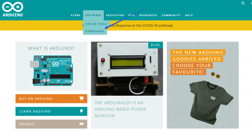
When we get max control board, we need to download Arduino IDE and driver firstly.You could download Arduino IDE from the official website:
https://www.arduino.cc/, click the SOFTWARE on the browse bar, click “DOWNLOADS” to enter download page, as shown below:
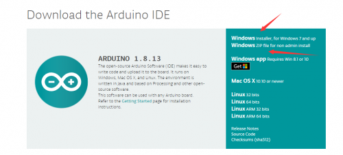
There are various versions Of IDE for Arduino, just download a version that compatible with your system, here we will show you how to download and install the windows version Arduino IDE.
There are two IDE versions for WINDOWS system, you can choose between the Installer (.exe) and the Zip packages. We suggest you use the first one that installs directly everything you need to use the Arduino Software (IDE), including the drivers. With the Zip package you need to install the drivers manually. The Zip file is also useful if you want to create a portable installation.
You just need to click JUST DOWNLOAD.
Arduino IDE Setting
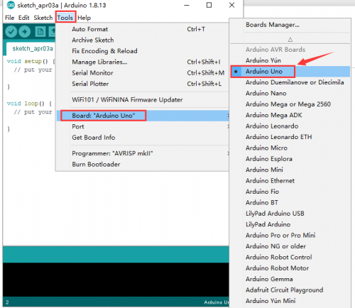
To avoid the errors when uploading the program to the board, you need to select the correct Arduino board that matches the board connected to your computer. Then come back to the Arduino software, you should click Tools→Board, select the board. (as shown below)
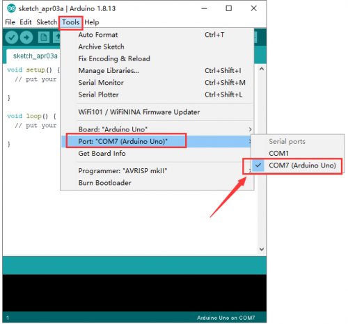
Then select the correct COM port (you can see the corresponding COM port after the driver is successfully installed)
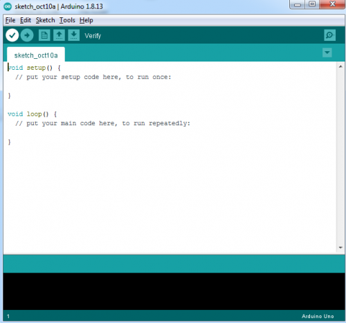
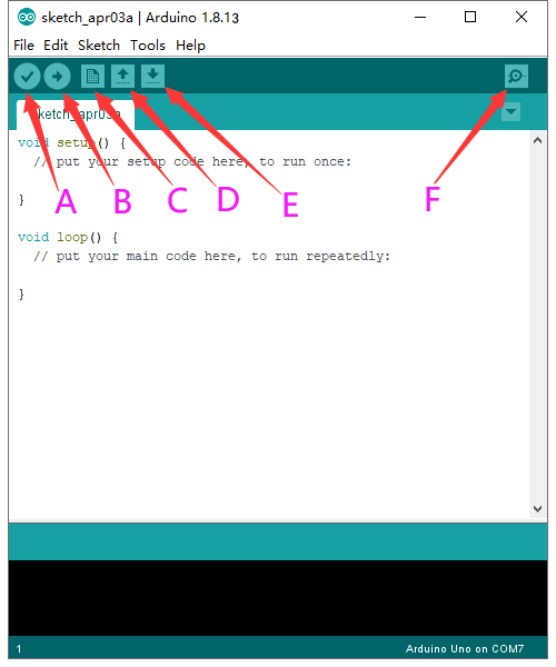
Before uploading the program to the board, let’s demonstrate the function of each symbol in the Arduino IDE toolbar.
- A- Used to verify whether there is any compiling mistakes or not.
- B- Used to upload the sketch to your Arduino board.
- C- Used to create shortcut window of a new sketch.
- D- Used to directly open an example sketch.
- E- Used to save the sketch.
- F- Used to send the serial data received from board to the serial monitor.
Start First Program
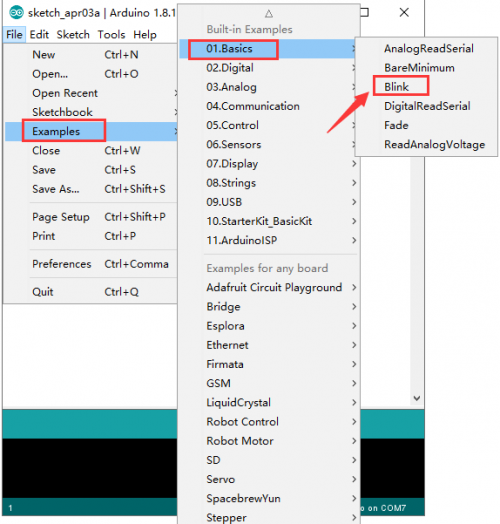
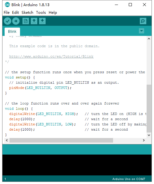
Open the file to select Example, choose BLINK from BASIC, as shown below:
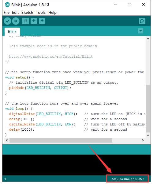
Set board and COM port, the corresponding board and COM port are shown on the lower right of IDE.
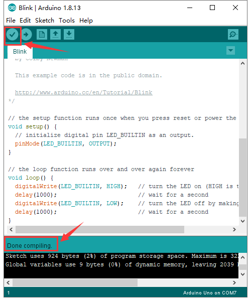
Click![]() to start compiling the program, check errors.
to start compiling the program, check errors.
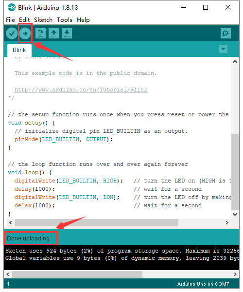
Click![]() to upload the program, upload successfully.
to upload the program, upload successfully.
Upload the program successfully, the onboard LED lights on for 1s, lights off for 1s. Congratulation, you finish the first program.
Max development board Project
Project 1 Hello world
As the beginning of all programming languages, Hello world occupies an unchangeable position, so the first project of our Arduino tutorial starts with hello world.
The "Hello, world" program refers to a computer program that outputs the string "Hello, world" on the computer screen.
In this project, the computer is the Max control board and the screen is the serial monitor. This project only needs one development board and one USB cable.
2.Tips:
After connecting the Max development board, open the Arduino IDE and ensure two points:
1. Select the correct development board version in Tools>Board (Max development board is compatible with Arduino UNO, so choose Arduino UNO for the board model in the software)
2. In Tools>Port, select the serial port where the Max development board is located.
3.Project code:
/*
keyestudio Max Development Board
Project 1
hello world
http://www.keyestudio.com
*/
int val;//define variable val
void setup()
{
Serial.begin(9600);//Set the baud rate to 9600, which must be consistent with the software settings.
}
void loop()
{
val=Serial.read();//Read the instructions or characters sent by the PC to the Arduino and assign them to val
if(val=='h')//Judging whether the received command or character is "h".
{//If the received is "h"
Serial.println("Hello World!");//Display "Hello World!"
}}
//*********************************************************
4.Project results
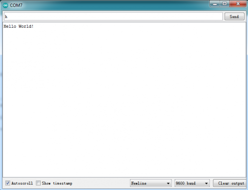
Open the Arduino IDE, copy and paste the code in the IDE, click Verify to compile, and check the program for errors. At this time, the code has not been uploaded to the Max board. Click upload, you can see the TX and RX LEDs on the Max board flash a few times, and the IDE prompts Done uploading. Upload the code to the development board, when enter "h" in the Serial Monitor, it will display "Hello, world!".
Project 2 LED blink
1.Project instruction
The next step is to start a very classic project-blink.This project is to light up an LED and control the delay time.It is an entry-level project for Arduino beginners.
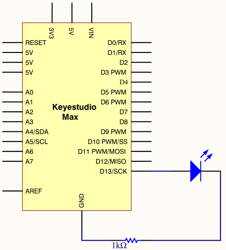
In this example, the LED we use is an LED onboard MAX,As shown in the picture below, it is directly connected to the D13 pin.
2.Project Principle:
LED is a type of semiconductor called "Light Emitting Diode "which is an electronic device made of semiconductor materials (silicon, selenium, germanium, etc.). It is dubbed indicator, digital and word display in circuit and device.
3.Project circuit:
4.Project code:
/*
keyestudio Max Development Board
Project 2
Blink
http://www.keyestudio.com
*/
// the setup function runs once when you press reset or power the board
void setup() {
  // initialize digital pin 13 as an output.
  pinMode(13, OUTPUT);
}
// the loop function runs over and over again forever
void loop() {
  digitalWrite(13, HIGH);   // turn the LED on (HIGH is the voltage level)
  delay(1000);              // wait for a second
  digitalWrite(13, LOW);    // turn the LED off by making the voltage LOW
  delay(1000);              // wait for a second
}//*********************************************************
When the upload is successful, it will prompt "Done uploading". After everything is successful, you can see the LED of D13 is on for one second and off for one second.
5.Code description:
setup():function is the basic function of the Arduino program and must be included. It will only be executed once when the program is running. It is commonly used to define pins and declare variables.
loop(): loop function is also a necessary function of the Arduino program. Its function is to run after setup() is executed once, and it keeps repeating.
digitalWrite(13, HIGH): Set the output voltage of the pin to high or low. Here D13 is high level, so that the LED can light up.
delay(1000):The delay function is a delay function, the value here is 1000, the unit is milliseconds (ms), 1000ms is 1 second.
What if you want to make the LED flash faster? Yes, you only need to modify the delay. Decrease the value, it means that the waiting time is shorter, that is, the flashing is faster. or, the flash is slower.
Project 3 SOS light
1.Project instruction
SOS is a Morse code distress signal (▄▄▄▄▄▄▄▄▄▄▄▄▄▄▄▄▄▄▄▄▄▄▄▄▄▄), used internationally, that was originally established for maritime use. In formal notation SOS is written with an overscore line, to indicate that the Morse code equivalents for the individual letters of "SOS" are transmitted as an unbroken sequence of three dots / three dashes / three dots, with no spaces between the letters.[1] In International Morse Code three dots form the letter "S" and three dashes make the letter "O", so "S O S" became a common way to remember the order of the dots and dashes. (IWB, VZE, 3B, and V7 form equivalent sequences, but traditionally SOS is the easiest to remember.)
2.Project Principle:
We could produce a letter through LED on and off state, long and short flash respectively represent dot and dash.
Through Morse code table,“S”is represented by three dots, therefore, we replace three dots with short flash, dash symbolizes letter“O”, replace threw dashes with long flash.
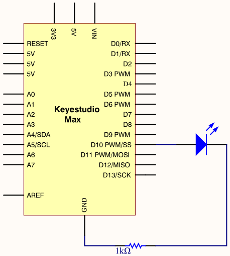
3.Project circuit:
4.Project code:
/*
keyestudio Max Development Board
Project 3
s o s
http://www.keyestudio.com
*/
int ledPin = 10;
void setup() {
 pinMode(ledPin, OUTPUT);
}
void loop() {
        //  stand for“ S”with three quick flash
       for(int x=0;x<3;x++){
               digitalWrite(ledPin,HIGH);            //set LED on
               delay(150);                           //delay in 150ms
               digitalWrite(ledPin,LOW);             //set LED off
               delay(100);                           //delay 100ms
       }
               // time gap to produce next letter
        delay(100);

         //stand for“ O”with three short flash
         for(int x=0;x<3;x++){
                digitalWrite(ledPin,HIGH);            //set LED on
                delay(400);                           //delay in 400ms
                digitalWrite(ledPin,LOW);             //set LED off
                delay(100);                           //delay in 100ms
          }

          // time gap to produce next letter
          delay(100);

          // stand for“ S”with three quick flash
          for(int x=0;x<3;x++){
                  digitalWrite(ledPin,HIGH);            //set LED on
                  delay(150);                           //delay in 150ms
                  digitalWrite(ledPin,LOW);             //set LED off
                  delay(100);                           //delay in 100ms
            }

           // wait 5s before repeating S.0.S signal
           delay(5000);
}
Upload code to Arduino, we will view LED flash S.O.S signal and wait for 5s and flash again. Plug external power in Arduino, and place them in a waterproof box, then S.O.S signal can be sent.
S.O.S signal is usually applied in maritime use and mountain-climbing.
Project 4 Breathing LED
1.Project instruction
We have learned how to control LED on and off, besides, the light intensity of LED can be controlled by program. The pins marked with“~”on Arduino board indicate they have PWM function. In this project, we will control LED brightness through PWM to simulate breathing effect.
2.Project Principle:
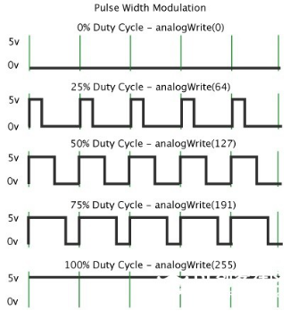
PWM is a means of controlling the analog output via digital means. Digital control is used to generate square waves with different duty cycles (a signal that constantly switches between high and low levels) to control the analog output.In general, the input voltage of port are 0V and 5V. What if the 3V is required? Or what if switch among 1V, 3V and 3.5V? We can’t change resistor constantly. For this situation, we need to control by PWM.
In the above figure, the green line represents a period, and value of analogWrite() corresponds to a percentage which is called Duty Cycle as well. Duty cycle implies that high-level duration is divided by low-level duration in a cycle. From top to bottom, the duty cycle of first square wave is 0% and its corresponding value is 0. The LED brightness is lowest, that is, turn off. The more time high level lasts, the brighter the LED. Therefore, the last duty cycle is 100%, which correspond to 255, LED is brightest. 25% means darker. PWM mostly is used for adjusting the LED brightness or rotation speed of motor.
3.Project circuit:
4.Project code:
/*
keyestudio Max Development Board
Project 4
Breathing LED
http://www.keyestudio.com
*/

int ledPin = 10;
int value;
void setup() {
     pinMode(ledPin,OUTPUT);
}

void loop()
{
  for (value = 0 ; value < 255; value=value+1)
  {
    analogWrite(ledPin, value);
    delay(5);
  }
  for (value = 255; value >0; value=value-1)
  {
    analogWrite(ledPin, value);
    delay(5);
  }
}
Upload test code successfully, LED gradually becomes brighter then darker, like human breath, rather than turn on and off immediately.
5.Code description:
Function analogWrite().
We know that digital port only has two state of 0 and 1. So how to send an analog value to a digital value? Here,this function is needed. Let’s observe the Arduino board and find 6 pins marked“~”which can output PWM signals.
The formula as follows:
analogWrite(pin,value)
analogWrite() is used to write an analog value from 0~255 for PWM port, so the value is in the range of 0~255. Attention that you only write the digital pins with PWM function, such as pin 3, 5, 6, 9, 10, 11.
Project 5 Traffic light
1.Project instruction
In the previous program, we have done the LED blinking experiment with one LED. Now, it’s time to up the stakes to do a bit more complicated experiment-traffic light. Actually, these two experiments are similar. While in this traffic light experiment, we use three LEDs with different colors rather than an LED.
2.Project Principle:
Max board imitates traffic light by controlling flashing time of LED through program.
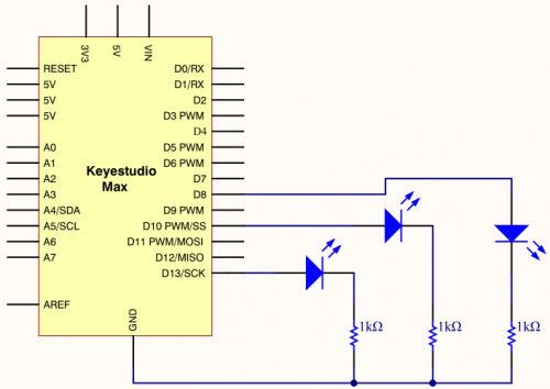
3.Project circuit:
4.Project code:
/*
keyestudio Max Development Board
Project 5
Traffic light
http://www.keyestudio.com
*/
int redled =8; // initialize digital pin 8.
int greenled =10; // initialize digital pin 10.
int yellowled =13; // initialize digital pin 13.
void setup()
{
pinMode(redled, OUTPUT);// set the pin with red LED as“output”
pinMode(yellowled, OUTPUT); // set the pin with yellow LED as“output”
pinMode(greenled, OUTPUT); // set the pin with green LED as“output”
}
void loop()
{
digitalWrite(greenled, HIGH);//// turn on green LED
delay(5000);// wait 5 seconds
digitalWrite(greenled, LOW); // turn off green LED
for(int i=0;i<3;i++)// blinks for 3 times
{
delay(500);// wait 0.5 second
digitalWrite(yellowled, HIGH);// turn on yellow LED
delay(500);// wait 0.5 second
digitalWrite(yellowled, LOW);// turn off yellow LED
}
delay(500);// wait 0.5 second
digitalWrite(redled, HIGH);// turn on red LED
delay(5000);// wait 5 second
digitalWrite(redled, LOW);// turn off red LED
}
5.Project results:
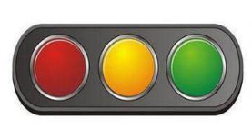
After downloading code, R, Y and G on control board correspond traffic lights. Green LED is turned on for 5s, then yellow LED flashes three times and red LED is turned on 5s and off.
Project 6 LED Chasing Effect
1.Project instruction
Flow light is commonly viewed in our daily life, such as on building, advertisement board and so on. We will show you how to make a flow light in this part.
3.Project code:
/*
keyestudio Max Development Board
Project 6
LED Chasing Effect
http://www.keyestudio.com
*/

int  redled = 8;
int  greenled = 10;
int  yellowled =13;
void  setup(){
 pinMode(redled, OUTPUT);
 pinMode(greenled, OUTPUT);
 pinMode(yellowled, OUTPUT);

 }
    void loop()
    {
    digitalWrite(redled, HIGH);//turn on red light
    delay(100);//delay in 0.1s
    digitalWrite(redled, LOW); //turn off red light
    delay(100);//delay in 1s
    digitalWrite(greenled, HIGH);//turn on green light
    delay(100);//delay in 0.1s
    digitalWrite(greenled, LOW);//turn off green light
    delay(100);//delay in 0.1s
    digitalWrite(yellowled, HIGH);//turn on yellow light
    delay(100);//delay in 0.1s
    digitalWrite(yellowled, LOW);//turn off yellow light
    delay(100);//delay in 0.1s
     }
5.Project results:
After downloading code, we will view red, yellow and green LEDs flash ceaselessly.
Project 7 Play Music
1.project instruction
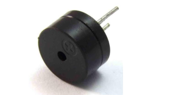
We can use Arduino to make many interactive works. The most commonly used one is acoustic-optic display. All the previous experiment has something to do with LED. However, the circuit in this experiment can produce sound. Normally, the experiment is done with a buzzer but not a speaker while buzzer is more simpler and easier to use.
The buzzer we introduced here is a passive buzzer. It cannot be actuated by itself, but by external pulse frequencies. ]
Different frequency produces different sound. We can use Arduino to code the melody of a song, which is quite fun and simple.
2.Project Principle:
Passive buzzer is an integrated electronic buzzer without vibration source inside. It must be driven by 2K-5K square wave instead of direct current signals. There is little difference between the two buzzers, but when the pins of the two buzzers are placed up, the passive buzzer comes with green circuit board, and the one sealed with vinyl is an active buzzer.
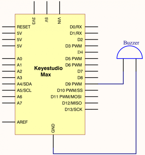
3.Project circuit:
/*
keyestudio Max Development Board
Project 7
Play Music
http://www.keyestudio.com
*/

int  tonepin=9;// set pin9 connecting buzzer
    void setup()
    {
      pinMode(tonepin,OUTPUT);//set IO port to output
    }
    void loop()
    {
      unsigned char i,j;
      while(1)
      {
        for(i=0;i<80;i++)//output a sound with frequency
        {
          digitalWrite(tonepin,HIGH);//emit a sound
          delay(1);//delay in 1ms
          digitalWrite(tonepin,LOW);//don’t emit a sound
          delay(1);//delay 1 ms
        }
        for(i=0;i<100;i++)// output another sound with frequency, 100 controls frequency and can be adjusted also by yourselves
        {
          digitalWrite(tonepin,HIGH);
          delay(2);
          digitalWrite(tonepin,LOW);
          delay(2);
        }
      }
}
From the above code, delay in the“for”statement controls the frequency, like the control of a square wave. Setting the delay time to 1ms for high and level implies that the cycle of square wave is 2ms and the frequency of sound is 500HZ; meanwhile, setting the delay time is 2ms, indicates that the cycle of square wave is 4ms and the sound frequency is 250HZ.
The number 80 and 100 control the time in the“for”statement. 80 in the“for” statement stands for the number of cycle, that is, playing 80 pcs cycle takes 2ms, 160ms in total; equally, when setting the cycle of square wave to 4s, 100 indicates that playing 100 pcs cycle takes 4ms, 400me in total.
5.Project results:
After uploading code, passive buzzer of control board emits 160ms 500Hz sound then 400ms 250Hz sound.
Project 8 WS2812 RGB LED
1.project instruction
In this project, we will take a look at an interesting product called the WS2812B Addressable LEDs. They are individually addressable RGB LEDs and are also called by different names like NeoPixel by Adafruit, for example. In this tutorial, we will learn about the WS2812B LEDs, its internal structure and construction and also how to control individually addressable LEDs using Arduino.
2.Project Principle:
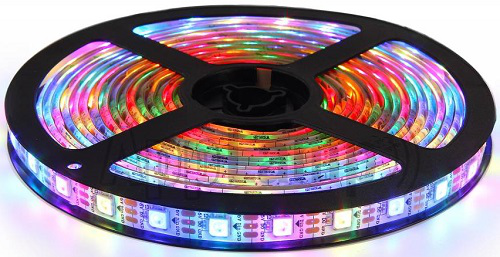
The WS2812B Addressable LED Strip is an intelligent light source that contains a control IC and an RGB LED in a same package, usually in SMD 5050 form factor. The following image shows a strip of WS2812B LEDs.
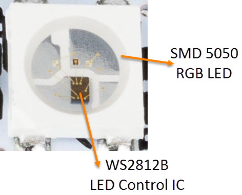
At first glance, it looks like a regular LED strip. But upon a closer inspection, you can find the WS2812B LED Control IC integrated into the SMD 5050 RGB LED Package. The following blown up image shows the same.
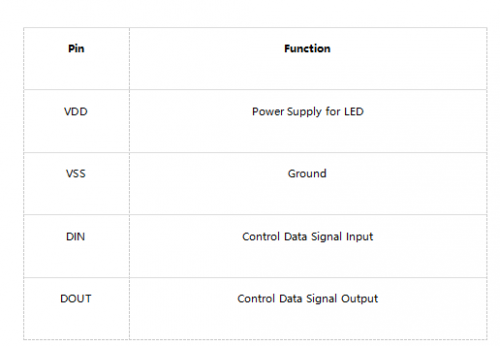
Individual WS2812B LED Block has four pins namely VDD, VSS (GND), DIN and DOUT. The functions of these pins are very simple and the following table gives a simple function description of the pins.
The power supply for the WS2812B IC is also supplied through the VDD Pin.
WS2812B LED Application Circuit
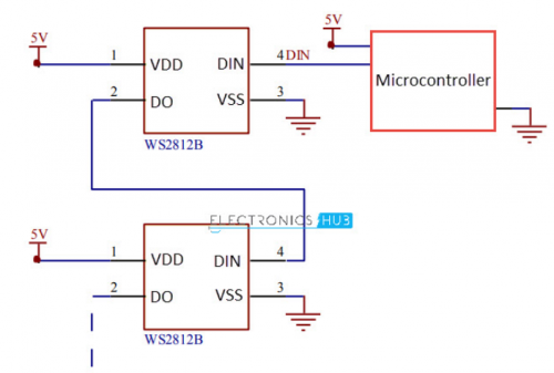
To understand how the WS2812B LEDs can be individually controlled, the following application circuit will be useful. All the WS2812B LEDs are connected in a cascade manner where the DO of the first LED is connected to the DIN of the second LED and so on.
But the first LED has to receive data through its DIN pin from a Microcontroller like Arduino. The following image shows the typical application circuit block diagram.
The data transfer protocol used by the WS2812B LEDs is NRZ Mode. The first DIN Port of the WS2812B LED array receives data from the microcontroller. The data for individual pixel is of 24-bit that consists of individual Red, Green and Blue LED control data of 8-bits each. The order of data must be GRB and the composition of the 24-bit data is shown below. Note that HIGH bit data is sent first.
Once the first WS2812B Block receives the first 24-bit data, the data is sent to its internal latch for further decoding. The remaining data is reshaped by its signal reshaping and amplification circuit and is passed to the next pixel in the cascade through the DO pin.
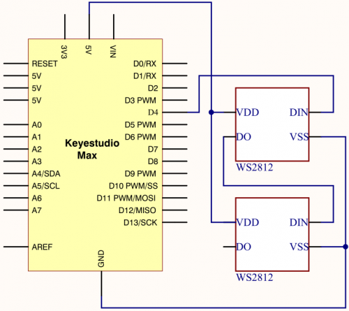
3.Project circuit:
4.Project code:
/*
keyestudio Max Development Board
Project 8
WS2812 RGB LED
http://www.keyestudio.com
*/
#include <Adafruit_NeoPixel.h>
#ifdef __AVR__
#include <avr/power.h>
#endif

#define PIN 4

// Parameter 1 = number of pixels in strip
// Parameter 2 = Arduino pin number (most are valid)
// Parameter 3 = pixel type flags, add together as needed:
//   NEO_KHZ800  800 KHz bitstream (most NeoPixel products w/WS2812 LEDs)
//   NEO_KHZ400  400 KHz (classic 'v1' (not v2) FLORA pixels, WS2811 drivers)
//   NEO_GRB     Pixels are wired for GRB bitstream (most NeoPixel products)
//   NEO_RGB     Pixels are wired for RGB bitstream (v1 FLORA pixels, not v2)
Adafruit_NeoPixel strip = Adafruit_NeoPixel(2, PIN, NEO_GRB + NEO_KHZ800);

// IMPORTANT: To reduce NeoPixel burnout risk, add 1000 uF capacitor across
// pixel power leads, add 300 - 500 Ohm resistor on first pixel's data input
// and minimize distance between Arduino and first pixel.  Avoid connecting
// on a live circuit...if you must, connect GND first.

void setup() {
  // This is for Trinket 5V 16MHz, you can remove these three lines if you are not using a Trinket
  #if defined (__AVR_ATtiny85__)
    if (F_CPU == 16000000) clock_prescale_set(clock_div_1);
  #endif
  // End of trinket special code


  strip.begin();
  strip.show(); // Initialize all pixels to 'off'
}

void loop() {
  // Some example procedures showing how to display to the pixels:
  colorWipe(strip.Color(255, 0, 0), 50); // Red
  colorWipe(strip.Color(0, 255, 0), 50); // Green
  colorWipe(strip.Color(0, 0, 255), 50); // Blue
  // Send a theater pixel chase in...
  theaterChase(strip.Color(127, 127, 127), 50); // White
  theaterChase(strip.Color(127, 0, 0), 50); // Red
  theaterChase(strip.Color(0, 0, 127), 50); // Blue

  rainbow(20);
  rainbowCycle(20);
  theaterChaseRainbow(50);
}

// Fill the dots one after the other with a color
void colorWipe(uint32_t c, uint8_t wait) {
  for(uint16_t i=0; i<strip.numPixels(); i++) {
    strip.setPixelColor(i, c);
    strip.show();
    delay(wait);
  }
}

void rainbow(uint8_t wait) {
  uint16_t i, j;

  for(j=0; j<256; j++) {
    for(i=0; i<strip.numPixels(); i++) {
      strip.setPixelColor(i, Wheel((i+j) & 255));
    }
    strip.show();
    delay(wait);
  }
}

// Slightly different, this makes the rainbow equally distributed throughout
void rainbowCycle(uint8_t wait) {
  uint16_t i, j;

  for(j=0; j<256*5; j++) { // 5 cycles of all colors on wheel
    for(i=0; i< strip.numPixels(); i++) {
      strip.setPixelColor(i, Wheel(((i * 256 / strip.numPixels()) + j) & 255));
    }
    strip.show();
    delay(wait);
  }
}

//Theatre-style crawling lights.
void theaterChase(uint32_t c, uint8_t wait) {
  for (int j=0; j<10; j++) {  //do 10 cycles of chasing
    for (int q=0; q < 3; q++) {
      for (int i=0; i < strip.numPixels(); i=i+3) {
        strip.setPixelColor(i+q, c);    //turn every third pixel on
      }
      strip.show();

      delay(wait);

      for (int i=0; i < strip.numPixels(); i=i+3) {
        strip.setPixelColor(i+q, 0);        //turn every third pixel off
      }
    }
  }
}

//Theatre-style crawling lights with rainbow effect
void theaterChaseRainbow(uint8_t wait) {
  for (int j=0; j < 256; j++) {     // cycle all 256 colors in the wheel
    for (int q=0; q < 3; q++) {
      for (int i=0; i < strip.numPixels(); i=i+3) {
        strip.setPixelColor(i+q, Wheel( (i+j) % 255));    //turn every third pixel on
      }
      strip.show();

      delay(wait);

      for (int i=0; i < strip.numPixels(); i=i+3) {
        strip.setPixelColor(i+q, 0);        //turn every third pixel off
      }
    }
  }
}

// Input a value 0 to 255 to get a color value.
// The colours are a transition r - g - b - back to r.
uint32_t Wheel(byte WheelPos) {
  WheelPos = 255 - WheelPos;
  if(WheelPos < 85) {
    return strip.Color(255 - WheelPos * 3, 0, WheelPos * 3);
  }
  if(WheelPos < 170) {
    WheelPos -= 85;
    return strip.Color(0, WheelPos * 3, 255 - WheelPos * 3);
  }
  WheelPos -= 170;
  return strip.Color(WheelPos * 3, 255 - WheelPos * 3, 0);
}
5. Project results:
After downloading code, two WS2812 RGB LEDs start blinking different colors, then stop flashing, and change different colors.
Project 9 To make a lamp
1.Project instruction
In previous lessons, we have known the output function of Arduino. In this experiment, we will make you have better understanding of I/O function through an LED experiment.
2.Project principle:
The push button switch is usually used to turn on and off the control circuit, and it is a kind of control switch appliance that is widely used.
The push button switch can complete basic controls such as start, stop, forward and reverse rotation, speed change and interlock. Usually each push button switch has two pairs of contacts. Each pair of contacts consists of a NO contact and a NC contact. When the button is pressed, the two pairs of contacts act simultaneously, the NC contact is disconnected, and the NO contact is closed.
3.Project circuit:
4.Project code:
/*
keyestudio Max Development Board
Project 9
To make a lamp
http://www.keyestudio.com
*/

int ledpin1=13;//define digital 13
int ledpin2=10;////define digital 10
int buttonpin1=2;//define digital 2
int buttonpin2=3;//define digital 3
int val1;//define variable val1
int val2;//define variable val2

void setup()
{
pinMode(ledpin1,OUTPUT);//define LED pin1 to output
pinMode(ledpin2,OUTPUT);//define LED pin2 to output
pinMode(buttonpin1,INPUT);//define button pin1 to input
pinMode(buttonpin2,INPUT);//define button pin2 to input
}
void loop()
{
val1=digitalRead(buttonpin1);//read the level of digital 2 and set to val
val2=digitalRead(buttonpin2);//read the level of digital 3 and set to val
if(val1==HIGH)//detect if the button is pressed, LED on when pressed
{
  digitalWrite(ledpin1,LOW);
}
else
{
  digitalWrite(ledpin1,HIGH);
}

if(val2==HIGH)//detect if the button is pressed, LED on when pressed
{
  digitalWrite(ledpin2,LOW);
}
else
{
  digitalWrite(ledpin2,HIGH);}
}
5. Project results:
This principle is applied widely in all kinds of circuit and household appliances, such as push switch, indicator and backlight of cellphone.
Project 10 To make a night light
1.Project instruction
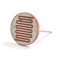
A photoresistor, relies on light to work. In the dark environment, it has high resistance. The stronger the light intensity is, the smaller its value is,thereby, we could check the light intensity through reading its resistance value.
We will make a photo-sensitive light which will adjust its light intensity with the ambient environment.
2.Project Principle:
Photoresistor , a kind of special electronic component, can transfer light signals into electronic signals. It contains special light-conductive material and is sealed with plastic and glass packaging. As the light is irradiated on this kind of photo-conductive material, its the resistance value will get small rapidly.
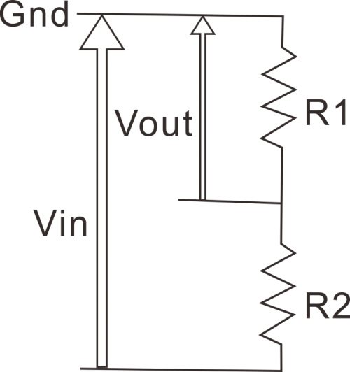
The photoresistor has a very high resistance in a dark environment. The stronger the light, the lower the resistance value. As the resistance value at both ends decreases, the Vout voltage increases (the value read from the analog port also increases, and the value of the analog port 0~1023 corresponds to the voltage value of 0~5V).
Why does the voltage decrease? Then we need to explain through physics knowledge-the principle of partial pressure. Let us look at a typical voltage divider circuit and see how it works.
Input voltage Vin(5V) connected to two resistors, only measures the voltage of Vout on resistor R1. Its voltage is less than input voltage。
The formula of the voltage of Vout is as follows
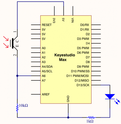
R1 represents 10k resistor, R2 is photoresistor. When R2 is in the dark environment, its value gets larger but Vout’s value is close to 0v. Once there is light, the value of R2 will get smaller and the value of Vout increases instead.
Judged from the above formula, R1 should be in 1k~10k, otherwise, the value of Vout is not apparent.
3.Project circuit:
4.Project code:
/*
keyestudio Max Development Board
Project10
To make a night light
http://www.keyestudio.com
*/
int LED = 13; // set LED to pin 13
int val = 0;   //set analog pin 0 to read the voltage value of photosensitive diode
void setup(){
pinMode(LED,OUTPUT);  // set LED to output
Serial.begin(9600);  // set serial baud rate to 9600
}
void loop(){
      val = analogRead(A6);  // read the voltage value 0~1023
      Serial.println(val); // check the change of voltage value in serial
      if(val>300)
      {   // once exceed the set value, LED will be off
      digitalWrite(LED,LOW);
      }else
      {  // otherwise, LED is on
      digitalWrite(LED,HIGH);
      }
      delay(10);   //delay in 10ms
}
5.Project results:
After wiring up hardware, open Arduino IDE to input code and LED will be on.
Turn on flashlight and point at photoresistor, LED is off. Once you move flashlight away, LED will be on again.
Project expansion:
For the test code, we read analog value of photoresistive diode through analog port.
Once the light is irradiated, the analog value read decreases. As the analog value is more than 300, LED will be off, on the contrary, the analog is less than and equivalent to 300, LED on.
Project 11 Voice-activated
1.Project instruction
Akin to a microphone, sound sensor can receive sound waves and show the vibration image of sound but not to measure the intensity of noise.
It has a built-in condenser electret microphone that is sensitive to sound.
The sound waves vibrate the electret film in the microphone, which causes the change of capacitance, and generates a correspondingly changed tiny voltage. This voltage is then converted into a 0-5V voltage, received by the data collector after A/D conversion, and sent to Arduino UNO.
2.Project Principle:
- Use 5v DC power supply (working voltage 3.3V-5V)
- With analog output AO, real-time microphone voltage signal output
- High sensitivity, electret condenser microphone (ECM) sensor
- Can detect the sound intensity of ambient environment.
Note: This sensor can only identify the presence or absence of sound (according to the principle of vibration) and cannot identify the size of the sound or the sound of a specific frequency.
3.Project circuit:
4.Project code:
/*
keyestudio Max Development Board
Project11
Voice-activated
http://www.keyestudio.com
*/
const int SOUND_PIN = A7;
const int LED_PIN = 13;
void setup() {
  pinMode(LED_PIN, OUTPUT);
  Serial.begin(9600);
}

void loop() {
  // read A7 analog signal
  int value = analogRead(SOUND_PIN);
  // output signal value
  Serial.println(value);
  if(value > 5){
    // more than threshold, pin 13 is high level and LED on    digitalWrite(LED_PIN, HIGH);
    delay(100);
  }else{
    // less than threshold, pin 13  is low level and LED off
    digitalWrite(LED_PIN, LOW);
    delay(100);
  }
}
5.Project results:
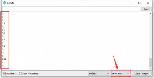
Download code, open serial monitor and set baud rate to 9600. The monitor shows the analog value detected by MIC. The louder the sound is, the larger the value is. In addition, as the analog value is more than 5, green LED will be on, otherwise, LED will be off.
Project 12 8*16 dot matrix-turn on a led
1.Project instruction
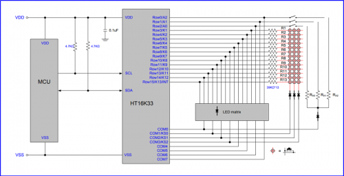
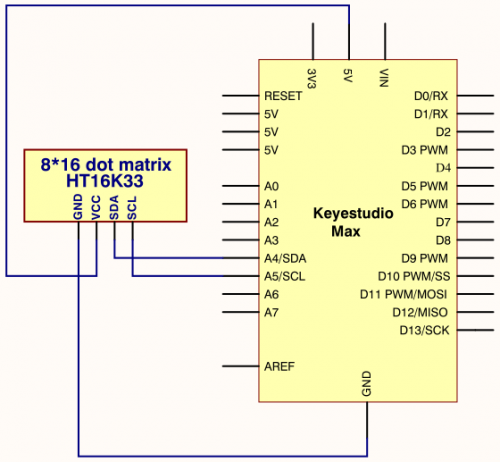
The 8*16 dot matrix integrated on the MAX board uses I2C communication. As long as 2 signal pins, up to 128 LEDs can be controlled, and interesting displays such as numbers, characters, and graphics can be displayed.
The 8*16 dot matrix is also great for making scrolling displays or small video displays. In our example, we set it up so words flow from one matrix to the other. Can be used for advertising display.
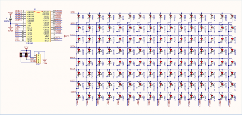
The 8*16 dot matrix uses a HT16K33 driver chip that does all the heavy lifting for you. This chip has a built in clock so they multiplex the display. Through a simple I2C interface, you can control the chip work and drive 8*16 Dot matrix screen.
Now we are about to start many 8*16 dot matrix projects, let’s first turn on a light on the dot matrix.
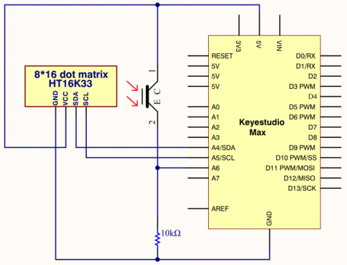
2.Project circuit:
3.Project Principle:
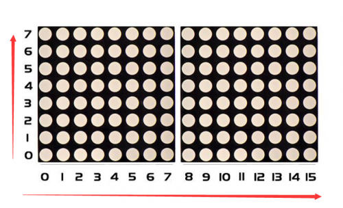
The display principle of 8*16 dot matrix is very simple. The single-chip microcomputer can drive 8*16 dot matrix through HT16K33 chip according to above circuit diagram. The arrangement of the dot matrix is as follows: 8 LED lights in the horizontal direction and 16 LED lights in the vertical direction. The total number of lights is 128. In order to quickly find the position of the light, we number the horizontal lights from 0-7, and the vertical lights from 0-15.
How to turn on a LED on dot matrix?
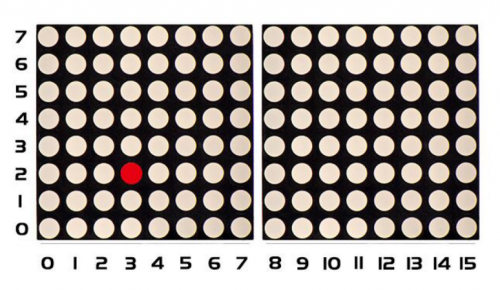
According to above picture, the coordinate of red point is(2,3), and we put coordinate value in the following code.
4.Project code:
/*
keyestudio Max Development Board
Project 12
 8*16 dot matrix-turn on a led
http://www.keyestudio.com
*/
#include <Wire.h>
#include "Keyestudio_LEDBackpack.h"
#include "Keyestudio_GFX.h"
Keyestudio_8x16matrix matrix = Keyestudio_8x16matrix();
void setup()
{
 matrix.begin(0x70);  // pass in the address
}
void loop()
{
  matrix.clear();  // clear display
  matrix.drawPixel(2, 3, LED_ON);
  matrix.writeDisplay();  // write the changes we just made to the display
5.Project results:
After wiring up, opening Arduino IDE and downloading code. The LED (as shown below) turns on.
Project 13 8*16 dot matrix-turn on one line
1.project instruction In previous program, we light up a coordinate point. In this project, we will light up a row of LEDs.
2.Project Principle:
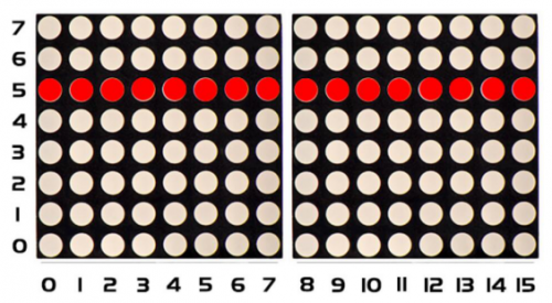
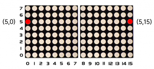
To light a row of LEDs, we need to make use of function matrix.drawLine. Lighting up the start and terminal point on a row of LEDs indicates all LEDs on this row are on, therefore, we need to decide the start and terminal point of this row of LEDs
Seeing from the above picture, the start point locates (5,0) and the end one is(5,15). Next, we place the value in the below code.
3.Project circuit:
4.Project code:
/*
keyestudio Max Development Board
Project 13
 8*16 dot matrix-turn on one line
http://www.keyestudio.com
*/
#include <Wire.h>
#include "Keyestudio_LEDBackpack.h"
#include "Keyestudio_GFX.h"
Keyestudio_8x16matrix matrix = Keyestudio_8x16matrix();
void setup()
{
 matrix.begin(0x70);  // pass in the address
}
void loop()
{
 matrix.clear();
 matrix.drawLine(5,0, 5,15, LED_ON);
 matrix.writeDisplay();  // write the changes we just made to the display
}
Project 14 8*16 dot matrix-draw a rectangle
1.Project instruction I believe that you get more interested in our programs. In this part, we will display a rectangle on 8*16 dot matrix.
2.Project Principle:
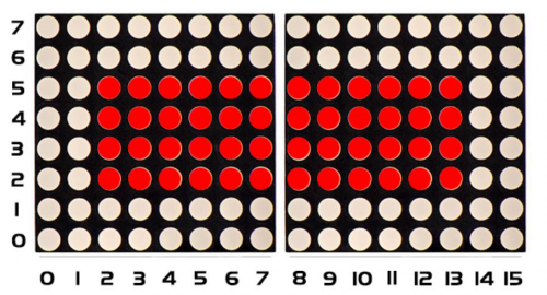
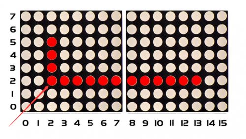
So, how to show a rectangle? We need use a function matrix.fillRect, which implies that you have to make sure a point on dot matrix so as to draw a square or rectangle, as shown below:
For example, we will draw a rectangle 4 in width and length in 12 from the point(2.2). What we need to do is put the value of width and length behind the point(2.2). Therefore, we get the code(2,2,4,12).
If display a square with 4 in width and length, its code are supposed to be (2,2, 4,4).
3.Project circuit:
4.Project code:
/*
keyestudio Max Development Board
Project 14
8*16 dot matrix-turn on a rectangle
http://www.keyestudio.com
*/

#include <Wire.h>
#include "Keyestudio_LEDBackpack.h"
#include "Keyestudio_GFX.h"
Keyestudio_8x16matrix matrix = Keyestudio_8x16matrix();
void setup()
{
 matrix.begin(0x70);  // pass in the address
}
void loop()
{
  matrix.clear();
  matrix.fillRect(2,2, 4,12, LED_ON);
  matrix.writeDisplay();  // write the changes we just made to the display
}
5.Project results:
After wiring up, opening Arduino IDE and downloading code. The corresponding LEDs is turned on.
Project 15 8*16 dot matrix-produce a circle
1.Project instruction In this program, we will generate a circle on 8*16 dot matrix.
2.Project Principle:
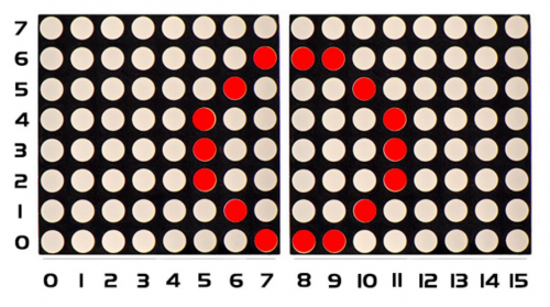
To show a circle with a radius of 3, we could use a function matrix.drawCircle. Select a central point to decide its coordinate and check radius value, as shown below:
The coordinate of center point of circle is(3,8), its radius is 3. We could put value(3,8, 3, )in the following code. If we want to draw a circle with a constant center point and a radius of 2, we just need to change the value behind coordinate of center point into 2.
3.Project circuit:
4.Project code:
/*
keyestudio Max Development Board
Project 15
 8*16 dot matrix-turn on a circle
http://www.keyestudio.com
*/
#include <Wire.h>
#include "Keyestudio_LEDBackpack.h"
#include "Keyestudio_GFX.h"
Keyestudio_8x16matrix matrix = Keyestudio_8x16matrix();
void setup()
{
 matrix.begin(0x70);  // pass in the address
}
void loop() {
 matrix.clear();
 matrix.drawCircle(3,8, 3, LED_ON);
 matrix.writeDisplay();  // write the changes we just made to the display
 delay(500);
}
5.Project results:
After wiring up, opening Arduino IDE and downloading code. The corresponding LEDs is turned on, as shown below:
Project 16 8*16 dot matrix-display texts and numbers
1.project instruction
In this project, we will make 8*16 dot matrix produce some numbers and texts, like advertisement board at bus station.
2.Project Principle:
This program is pretty easy. We only need to confirm the coordinate of texts and numbers. Let’s conduct an experiment to illustrate.
We set the display area to start from number 3 on horizontal coordinate and number zero on vertical coordinate, as shown below
We add the texts to be shown in the code matrix.print after getting the coordinate of text. Note: numbers can be shown directly, but texts need adding double quotes.
3.Project code:
/*
keyestudio Max Development Board
Project 16
 8*16 dot matrix-display text and numbers
http://www.keyestudio.com
*/
#include <Wire.h>
#include "Keyestudio_LEDBackpack.h"
#include "Keyestudio_GFX.h"
Keyestudio_8x16matrix matrix = Keyestudio_8x16matrix();
void setup()
{
 matrix.begin(0x70);  // pass in the address
}
void loop() {
 matrix.setTextSize(1);// set size of text
 matrix.setTextWrap(false);  // we dont want text to wrap so it scrolls nicely
 matrix.setTextColor(LED_ON);
 matrix.setRotation(1);// show rotation
 matrix.clear();
 matrix.setCursor(3,0);//set the coordinate of text
 matrix.print("OK");   //show OK
 matrix.writeDisplay();
 delay(1000);
 }
4.Project results:
After wiring up, opening Arduino IDE and downloading code. The control board shows“OK”, as shown below:
Project 17 8*16 dot matrix-display images
1.Project Instruction
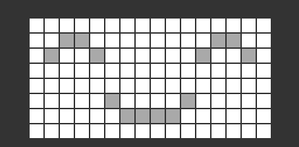
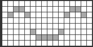
A large number of display devices, like cellphone, computer screen and advertisement board, are made of tiny light-emitting unit. The 8*16 dot matrix aren’t able to show exquisite and high pixel pictures but some cute and customized heart-shape picture, smiley face and so on, even though consisting of 128 pcs light-emitting units.
2. Project Principle:
- Introduction for Modulus Tool
- The online version of dot matrix modulus tool:
- http://dotmatrixtool.com/#
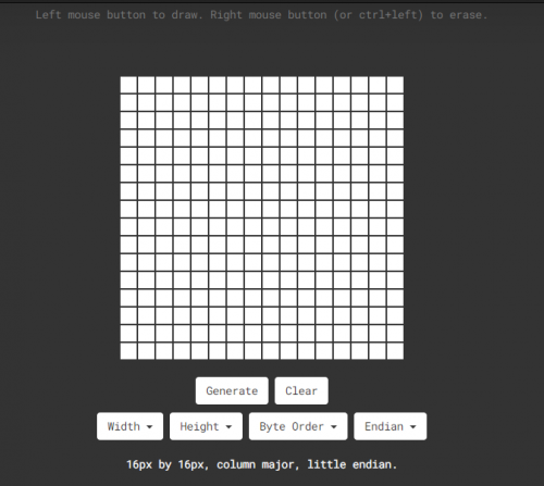
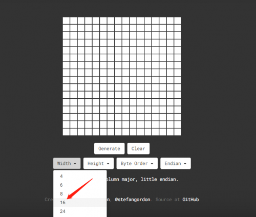
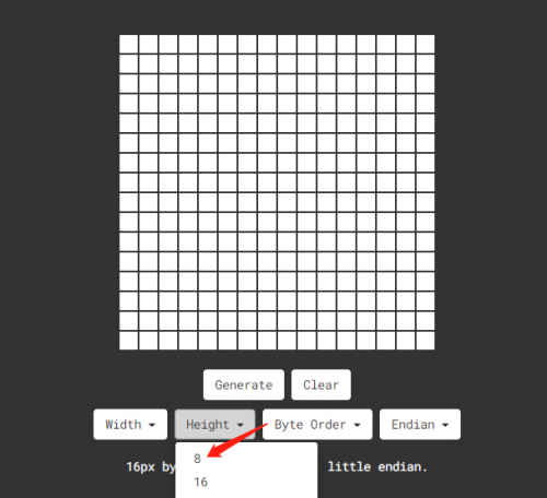
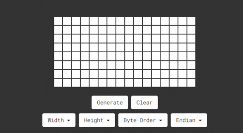
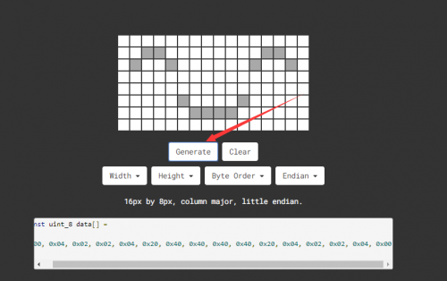
The dot matrix is 8*16 in this project, thereby, set the height to 8, width to 16, as shown below.
As same as dot matrix on Max board
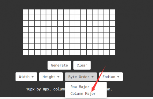
Click Byte order to select “column major”
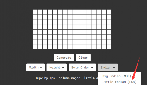
Tap endian to set little endian(lsb)
Then we draw the pattern we need.
Click generate to get hexadecimal code.
Move the above hexadecimal code into the code of the below program.
3. Project circuit:
4. Project code:
/*
keyestudio Max Development Board
Project 17
8*16 dot matrix-display images
http://www.keyestudio.com
*/
#include <Wire.h>
#include "Keyestudio_LEDBackpack.h"
#include "Keyestudio_GFX.h"
Keyestudio_8x16matrix matrix = Keyestudio_8x16matrix();
void setup()
{
 matrix.begin(0x70);  // pass in the address
}
static const uint8_t PROGMEM
smile_bmp[] =
{ 0x00, 0x04, 0x02, 0x02, 0x04, 0x20, 0x40, 0x40, 0x40, 0x40, 0x20, 0x04, 0x02, 0x02, 0x04, 0x00};
void loop() {
  //matrix.setRotation(1);
  matrix.clear();
  matrix.drawBitmap(0, 0, smile_bmp, 8, 16, LED_ON);
  matrix.writeDisplay();
  delay(1000);
}
5.Project results:
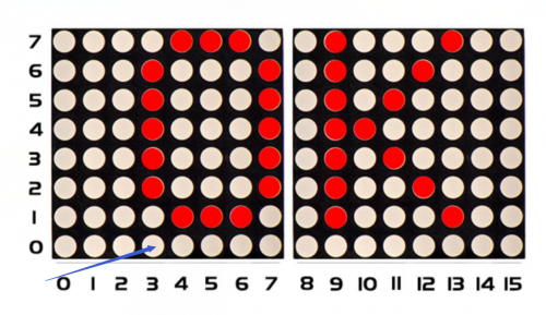
After wiring up, opening Arduino IDE and downloading code. The control board shows the following picture.
Project 18 8*16 dot matrix-knob control
1.Project instruction
There are on-board button switches on Max board, we will combine button switch and 8*16 dot matrix to make an interactive display.
2.Project principle:
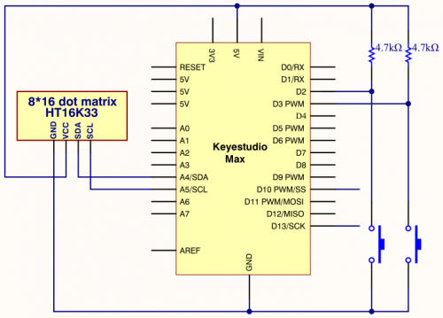
The signal pins of two buttons are connected to D2 and D3. Press left button, 8*16 dot matrix shows“L”; press right button, 8*16 dot matrix shows“R”.
3.Project circuit:
4.Project code:
/*
keyestudio Max Development Board
Project 18
8*16 dot matrix-knob control
http://www.keyestudio.com
*/
#include <Wire.h>
#include "Keyestudio_LEDBackpack.h"
#include "Keyestudio_GFX.h"
Keyestudio_8x16matrix matrix = Keyestudio_8x16matrix();
int K1=3;
int K2=2;
int x;
void setup()
{
 matrix.begin(0x70);  // pass in the address
  pinMode(K1,INPUT);
  pinMode(K2,INPUT);
  matrix.drawCircle(3,8, 3, LED_ON);
  matrix.writeDisplay();  // write the changes we just made to the display
}
void loop()
{
  int K1_level=digitalRead(K1);
  int K2_level=digitalRead(K2);
  if(K1_level==0)
{
  matrix.setTextSize(1);
  matrix.setTextWrap(false);  // we dont want text to wrap so it scrolls nicely
  matrix.setTextColor(LED_ON);
  matrix.setRotation(1);
  matrix.clear();
  matrix.setCursor(2,0);
  matrix.print("L");
  matrix.writeDisplay();
 }
  if(K2_level==0)
{
  matrix.setTextSize(1);
  matrix.setTextWrap(false);  // we dont want text to wrap so it scrolls nicely
  matrix.setTextColor(LED_ON);
  matrix.setRotation(1);
  matrix.clear();
  matrix.setCursor(9,0);
  matrix.print("R");
  matrix.writeDisplay();
}}
5. Project results:
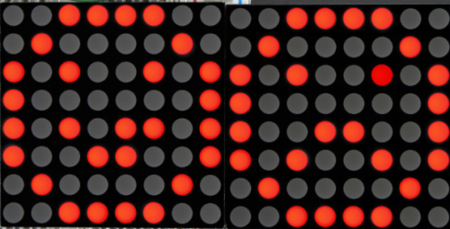
After the wiring-up, open Arduino IDE and download code. The control board shows the following picture.
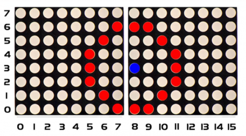
The dot matrix of control board shows letter O. However, the left dot matrix will show letter“L”when left button is pressed; on the contrary, the right dot matrix will display letter“R”.
Project 19 8*16 dot matrix-light control
1.Project Instruction
The light sensor feature that resistance is inverse proportion to to light intensity. Based on this characteristics, we made a night light. In this chapter, we will show you light column on dot matrix.
2.Project Principle:
The signal pin of light sensor is linked with A6 of MAX development board. 8*16 dot matrix will show light column, the darker the light intensity is, the shorter the height of light column.
3.Project circuit:
4.Project code:
/*
keyestudio Max Development Board
Project 19
8*16 dot matrix-light control
http://www.keyestudio.com
*/
#include <Wire.h>
#include "Keyestudio_LEDBackpack.h"
#include "Keyestudio_GFX.h"
int light = A6;
int Light_val;
Keyestudio_8x16matrix matrix = Keyestudio_8x16matrix();
void setup() {
  Serial.begin(9600);
  Serial.println("16x8 LED Matrix Test");
  pinMode(A6,INPUT);
  matrix.begin(0x70);  // pass in the address
}
void loop() {
  Light_val=analogRead(A6);
  Light_val=map(Light_val,0,1023,0,15);
   matrix.clear();
  matrix.drawLine(3,0, 3,Light_val, LED_ON);
  matrix.writeDisplay();  // write the changes we just made to the display
  delay(10);
}
5.Project results:
Wire up, open Arduino IDE and download code. Place the control board as follows:
The photoresistor of control board detects the light intensity. The stronger the light intensity is, the more LED on.
Project 20 8*16 dot matrix-sound control
1.Project instruction
In this lesson, we will create more fantastic programs with microphone sensor and 8*16 dot matrix
2.Project Principle:
The signal pin of microphone sensor is connected to A7 of Max development. The circle on dot matrix will enlarge with the sound intensity. The stronger the sound intensity, the larger the circle gets.
3.Project circuit:
4.Project code:
/*
keyestudio Max Development Board
Project 20
8*16 dot matrix-sound control
http://www.keyestudio.com
*/
#include <Wire.h>
#include "Keyestudio_LEDBackpack.h"
#include "Keyestudio_GFX.h"
int mic = A7;
Keyestudio_8x16matrix matrix = Keyestudio_8x16matrix();
int Mic_val;
void setup() {
Serial.begin(9600);
Serial.println("16x8 LED Matrix Test");
pinMode(mic,INPUT);
matrix.begin(0x70);  // pass in the address
}
void loop() {
  Mic_val=analogRead(mic);
  Mic_val=map(Mic_val,0,1023,0,10);
  matrix.clear();
  matrix.drawCircle(3,8,Mic_val, LED_ON);
  matrix.writeDisplay();  // write the changes we just made to the display
  delay(10);
}
5.Project results:
Open Arduino IDE and download code. The MIC component of control board tests the sound and the louder the sound is, the bigger the shown aperture is.
Project 21 8*16 dot matrix-game project
1.Project instruction
We could play games through Max development board. Can you imagine that?
Let’s get started.
2.Project Principle:
Game 1: gluttonous snake
Press two buttons on max board, the gluttonous snake moves clockwise and anticlockwise.
Note: 1.8.12 version Wire library is not compatible with code when testing code of game 2, you need change library in arduino-1.8.12\hardware\arduino\avr\libraries
Game 2: Breakout clone
Press buttons simultaneously to start.
3.Project circuit:
4.Project code1:
*******************************gluttonous snake ****************************
/*
keyestudio Max Development Board
Project 21
8*16 dot matrix-gluttonous snake
http://www.keyestudio.com
*/
#include <Wire.h>
#include <Keyestudio_GFX.h>
#include <Keyestudio_LEDBackpack.h>
// Button pin
const int buttonRightPin = 2;
const int buttonLeftPin  = 3;
int* buttonPin;
 int* buttonState;
// Game constants
// buttons
const int RIGHTBUTTON = 0;
const int LEFTBUTTON  = 1;
// direction
const int TOP    = 0;
const int RIGHT  = 1;
const int BOTTOM = 2;
const int LEFT   = 3;
// Snake
const int MAX_SNAKE_LENGTH = 100;
// Variables
//Keyestudio_8x8matrix matrix = Keyestudio_8x8matrix();  // Display
Keyestudio_8x16matrix matrix = Keyestudio_8x16matrix();
int direction = TOP;      // direction of movement
int snakeX[MAX_SNAKE_LENGTH];     // X-coordinates of snake
int snakeY[MAX_SNAKE_LENGTH];    // Y-coordinates of snake
int snakeLength = 1;        // nr of parts of snake
boolean buttonRead = false;            // is button already read in this loop
unsigned long prevTime = 0;          // for gamedelay (ms)
unsigned long delayTime = 500;        // Game step in ms
int fruitX, fruitY;
unsigned long fruitPrevTime = 0;
unsigned long fruitBlinkTime = 1000/250;
int fruitLed = LED_ON;
void setup(){
  Serial.begin(9600);
  Serial.println("Snake is started");
  randomSeed(analogRead(0));
  // Init led matrix
  matrix.begin(0x70);
  // init buttons
  int buttonpins[] = {buttonRightPin, buttonLeftPin};
  initButtons(buttonpins, 2);
  // init snake
  snakeX[0] = 4;
  snakeY[0] = 7;
  for(int i=1; i<MAX_SNAKE_LENGTH; i++){
    snakeX[i] = snakeY[i] = -1;
  }
  makeFruit();
}
void loop(){
  checkButtons();
  unsigned long currentTime = millis();
  if(currentTime - prevTime >= delayTime){
    nextstep();
    buttonRead = false;
    prevTime = currentTime;
  }
  draw();
}
void initButtons(int pinNumbers[], int length){
  Serial.println("initButtons");
  // Copy PIN numbers
  buttonPin = new int[length];
  for(int i=0; i<length; i++){
    buttonPin[i] = pinNumbers[i];
  }
  // Initialize button state
  buttonState = new int[length];
  for(int i=0; i<length; i++){
    buttonState[i] = LOW;
  }

  for(int i=0; i<length; i++)
  {
    Serial.print(buttonPin[i]);
    Serial.print(buttonState[i]);
  }
}
boolean buttonClicked(int index){
  // current state
  int state = digitalRead(buttonPin[index]);
  boolean buttonClick = false;
  // button has pressed
  if(buttonState[index] == HIGH){
    if(state == LOW){
      buttonClick = true;
    }
  }
  buttonState[index] = state;
  return buttonClick;
}
void checkButtons(){
  if(!buttonRead){
    int currentDirection = direction;
    if(buttonClicked(LEFTBUTTON)){
      direction--;
      if(direction < 0){
        direction = LEFT;
      }
    }
    else if(buttonClicked(RIGHTBUTTON)){
      direction++;
      if(direction > 3){
        direction = TOP;
      }
    }
    buttonRead = (currentDirection != direction);
  }
}

void draw(){
  matrix.clear();
  drawSnake();
  drawFruit();
  matrix.writeDisplay();
}
void drawSnake(){
  for(int i=0; i<snakeLength; i++){
    matrix.drawPixel(snakeX[i], snakeY[i], LED_ON);
  }
}
void drawFruit(){
  if(inPlayField(fruitX, fruitY)){
    unsigned long currenttime = millis();
    if(currenttime - fruitPrevTime >= fruitBlinkTime){
      fruitLed = (fruitLed == LED_ON) ? LED_OFF : LED_ON;
      fruitPrevTime = currenttime;
    }
    matrix.drawPixel(fruitX, fruitY, fruitLed);
  }
}
boolean inPlayField(int x, int y){
  return (x>=0) && (x<8) && (y>=0) && (y<16);
}
void nextstep(){
  for(int i=snakeLength-1; i>0; i--){
    snakeX[i] = snakeX[i-1];
    snakeY[i] = snakeY[i-1];
  }
  switch(direction){
    case TOP:
      snakeY[0] = snakeY[0]-1;
      break;
    case RIGHT:
      snakeX[0] = snakeX[0]+1;
      break;
    case BOTTOM:
      snakeY[0] = snakeY[0]+1;
      break;
    case LEFT:
      snakeX[0]=snakeX[0]-1;
      break;
  }
  if((snakeX[0] == fruitX) && (snakeY[0] == fruitY)){
    snakeLength++;
    if(snakeLength < MAX_SNAKE_LENGTH){
      makeFruit();
    }
    else {
      fruitX = fruitY = -1;
    }
  }
}
void makeFruit(){
  int x, y;
  x = random(0, 7);
  y = random(0, 15);
  while(isPartOfSnake(x, y)){
    x = random(0, 7);
    y = random(0, 15);
  }
  fruitX = x;
  fruitY = y;
}

boolean isPartOfSnake(int x, int y){
  for(int i=0; i<snakeLength-1; i++){
    if((x == snakeX[i]) && (y == snakeY[i])){
      return true;
    }
  }
  return false;
}//***********************************************************
5.Project code2:
*******************************Breakout clone**********************
/*
keyestudio Max Development Board
Project 21
8*16 dot matrix-Breakout clone
http://www.keyestudio.com
*/
#include <Wire.h>
#include "Keyestudio_LEDBackpack.h"
#include "Keyestudio_GFX.h"
#include "Breakout.h"
Keyestudio_8x16matrix matrix = Keyestudio_8x16matrix();
Breakout breakout;
int count = 0;
void setup() {
  Serial.begin(9600);
  Serial.println("8x16 LED Matrix Test");
  pinMode(L_PIN, INPUT);
  pinMode(R_PIN, INPUT);
  matrix.begin(0x70);  // pass in the address
  matrix.setBrightness(0);
}
void loop() {
  // action depends on game state - idealy the state should be a part of the Breakout class or a seperate logic class
  switch(state){
    // setup game
    case SETUP:
      breakout.restart();
      breakout.speed = START_SPEED;
      state = START;
      break;
      case START:
    // ready to start the game, changed to PLAY if the action button is pushed.
    // Change here if paddle should be able to move before you shoot the first ball and start the game.
      checkActions();
      if(actions == SEL){
      state = PLAY;
      }
      break;
      case LOST:
    // game lost
      breakout.lost();
      reDraw();
      blink(10, 100);
      breakout.restart();
      breakout.speed = START_SPEED;
      state = START;
      break;

    case WON:
    // game won
      breakout.won();
      reDraw();
      blink(10, 100);
      breakout.restart();
      state = START;
      break;
      case PLAY:
      // game in play
      {
        if(count > breakout.speed){
          checkControls();
          breakout.play(controls);
          count = 0;
          if(breakout.bricks == 128){
          state = WON;
          }
          if(breakout.ball.y == 7)
            state = LOST;
          }
        delay(20);
        count++;
      }
  }
  reDraw();
}

void reDraw(){
  for(int i = 0; i < 8; i++){
    for(int j = 0; j < 16; j++){   //change 8 into 16
      if(breakout.level[i][16-j-1] != 'E'){
        matrix.drawPixel(i,j,1);
      }
      else
        matrix.drawPixel(i,j,0);
    }
  }
  matrix.writeDisplay();
}

void checkActions(){
  int count = 0;
  while(count < 5 && (!digitalRead(R_PIN))&&(!digitalRead(L_PIN))){
    count++;
  }
  if(count > 4){
    actions = SEL;
    return;
  }
  actions = NO;
}
void checkControls(){
  int count = 0;
  while(count < 5 && (!digitalRead(L_PIN))){
    count++;
  }
  if(count > 4){
    controls = LEFT;
    return;
  }
  count = 0;
  while(count < 5 && (!digitalRead(R_PIN))){
    count++;
  }
  if(count > 4){
    controls = RIGHT;
    return;
  }
  controls = NONE;
}
void blink(int times, int wait){
  for(int i = 0; i < times; i++){
    matrix.setBrightness(2);
    matrix.writeDisplay();
    delay(wait);
    matrix.setBrightness(0);
    matrix.writeDisplay();
    delay(wait);
  }
}
5.Project results:
Open Arduino IED and download code 1. Next, you can play “Gluttonous Snake” game. The motion of snake can be controlled by D2 and D3 buttons of control board, in addition, the left button controls the anticlockwise movement and right button is for clockwise motion. Meanwhile, you can press reset button to restart game.
Download code 2, we can start “Breakout clone”. D2 and D3 can control left and right motion for control board. And press these two buttons simultaneously to start game. In the game, you have to make the falling light bounce to clear out bricks via the moving board , otherwise, you will fail.
