Ks0099 keyestudio EASY plug Control Board
Introduction
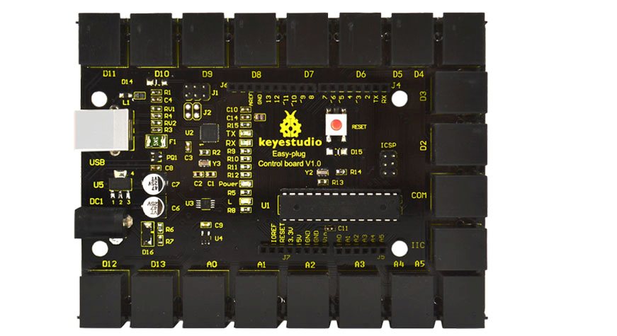
Keyestudio Easy-plug control board is a microcontroller board based on the ATmega328P-PU. It has 14 digital input/outputs (of which 6 can be used as PWM outputs), 6 analog inputs, a 16 MHz quartz crystal, a USB connection, a power jack, an ICSP header and a reset button. It contains everything needed to support the microcontroller; simply connect it to a computer with a USB cable or power it with a AC-to-DC adapter or battery to get started.You can tinker with your UNO without worrying too much about doing something wrong, worst case scenario you can replace the chip for a few dollars and start over again.
For convenience of wire connection, we simplify pins GND and VCC into each plug, so you only need one wire to connect a module, no need to separately connect the VCC and GND. The pins on the original UNO are all redesigned into plug interface. On the board, you can find ports D2-D13, A0 to A5, an IIC port and a COM port. All in one simple plug.].
Cautions
The warnings and wrong operations possible cause dangerous.
Schematic
Specifications
| Microcontroller core: | ATmega328P-PU |
|---|---|
| Working voltage: | +5V |
| External input voltage: | +7V~+12V(suggest) |
| External input voltage ( extremum ): | +6V≤ Vin ≤ +20V |
| Digital signal I/O interface: | 14 (of which 6 provide PWM output) |
| Analog signal input interface: | 6 |
| DCI/O interface current: | 20 mA |
| FlashMemory: | 32KB (ATmega328) of which 0.5 KB used by bootloader |
| SRAM static storage capacity: | 2KB |
| EEPROM storage capacity: | 1 KB |
| EEPROM storage capacity: | 16 MHz |
Board test
Following is a board test example called “Hello World!”.
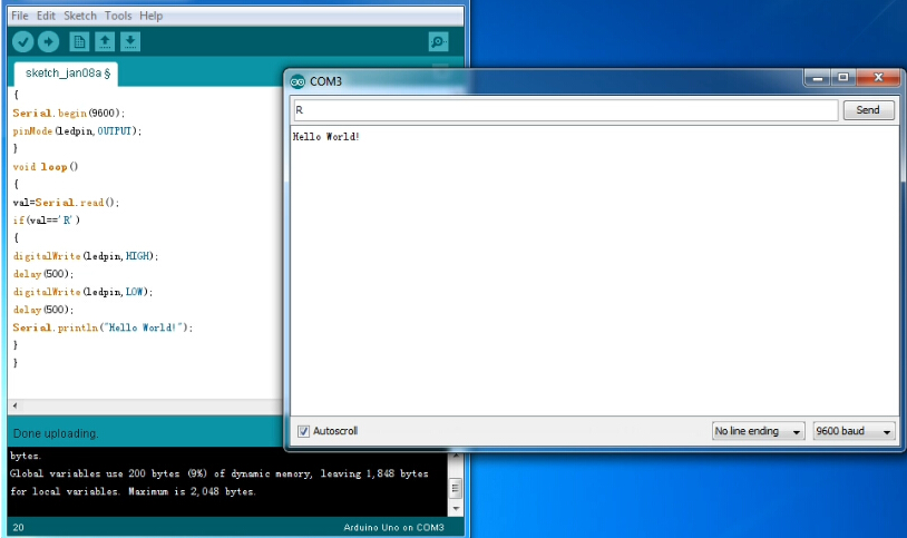
First, open Arduino IDE. In this example sketch, we program Arduino to display “Hello World!” in serial monitor when it receives a specific character string “R”; also the on-board D13 LED will blink once each time it receives “R”.
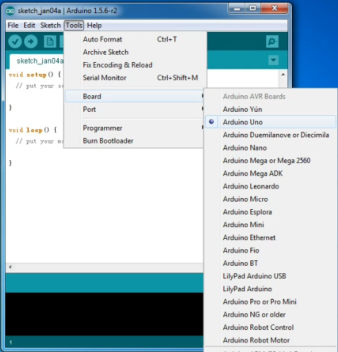
First, set up board; In “Tools”, select “Arduino Uno”.
Next, set up COM port; In “Tools”, select “COM3”.
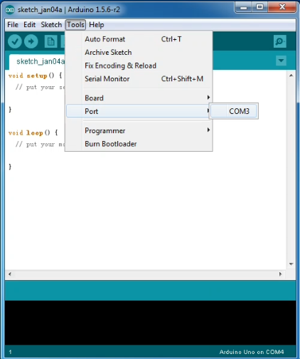
After selection, you can see indicated area is the same with settings in “Device manager”.
File:Ks0099-4.jpg
Copy the example sketch and paste it to the IDE; click “Verify ” to check compiling mistakes; click “Upload ” to upload the program to the board.
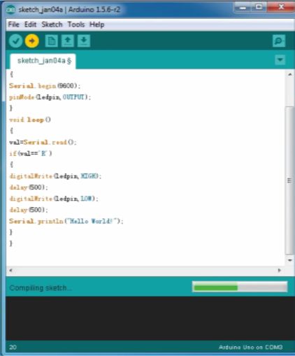
After uploading is done, open “serial monitor ”; enter “R”; click “Send”, the serial monitor will display “Hello World!” and the D13 LED will blink once.
Programming
int val; int ledpin=13 void setup() { Serial.begin(9600); pinMode(ledpin,OUTPUT); } void loop() { val=Serial.read(); if(val=='R') { digitalWrite(ledpin,HIGH); delay(500); digitalWrite(ledpin,LOW); delay(500); Serial.println("Hello World!"); } }
Support
If you have questions or other better design ideas, you can go to our forum or wish to discuss.
Additional Idea
The Additional Idea is the place to write your project ideas about this product, or other usages you've found. Or you can write them on Projects page.
How to Buy
Licensing
This documentation is licensed under the Creative Commons Attribution-ShareAlike License 3.0 Source code and libraries are licensed under GPL/LGPL, see source code files for details.
External Links
Links to external webpages which provide more application ideas, documents/datasheet or software libraries