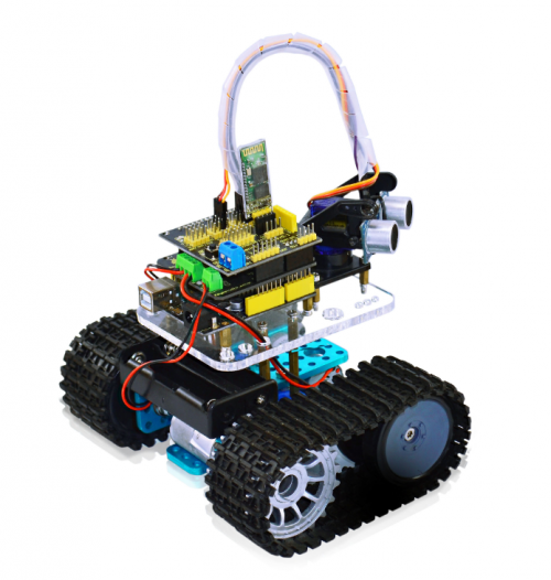
Ks0071 keyestudio Mini Tank Robot
keyestudio Mini Tank Robot
1.Introduction
Mini tank robot is a learning application development system of microcontroller based on Arduino. It has functions such as ultrasonic obstacle avoidance, Bluetooth remote control. This kit contains many interesting programs. It can also be expanded with external circuit modules to have other functions. This kit is designed to help you interestingly learn Arduino. You can learn
Arduino MCU development ability while having fun.
2.Parameters
1. Motor parameters: 6V, 150rpm/min
2. Use L298P driver module for motor control.
3. Equipped with Ultrasonic module, can detect whether there are obstacles ahead, and the distance between the Tank robot and the obstacles to realize obstacle avoidance function.
4. Equipped with Bluetooth wireless module, can remotely control the robot after pairing with mobile phone Bluetooth.
5. Can be connected to external 7 ~ 12V power supply; with various sensor modules, it can realize various functions.
3.Component list
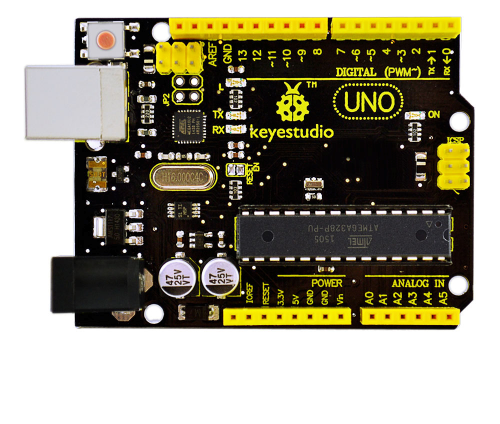
1. keyestudio UNO R3 controller * 1
2. keyestudio L298P shield * 1
3. keyestudio V5 sensor shield * 1
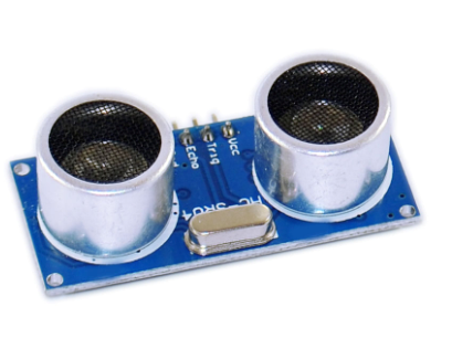
4. HC-SR04 ultrasonic sensor module * 1
5. keyestudio Bluetooth Module (HC-06) * 1
6. Plastic platform (PC) * 1
7. Servo motor * 1
8. Transparent Acrylic board * 1
9. Metal holder * 4
10. Tank driver wheel * 2
11. Tank load-bearing wheel * 2
12. Caterpillar band * 2
13. Metal motor * 2
14. Copper coupler * 2
15. 18650 2-cell battery case * 1
16. USB cable (1m) * 1
17. Copper bush * 2
18. Flange bearing * 4
19. Hexagon copper bush (M3*10MM) * 4
20. Hexagon copper bush (M3*45MM) * 4
21. Round Screw (M3*6MM) * 10
22. Round Screw (M4*35MM) * 4
23. Inner hexagon screw (M3*8MM) * 10
24. Inner hexagon screw (M3*20MM) * 6
25. Inner hexagon screw (M3*25MM) * 6
26. Inner hexagon screw (M4*10MM) * 6
27. Inner hexagon screw (M4*50MM) * 2
28. M3 Nut * 6
29. M4 self-locking nut * 2
30. M4 nut * 15
31. Connector wire (150mm, black) * 2
32. Connector wire (150mm, red) * 2
33. F-F Dupont wire (20CM, 4Pin) * 1
34. Supporting part (27*27*16MM, blue) * 2
35. Winding wire (12CM) * 1
- Self-prepare part
18650 rechargeable battery * 2
18650 charger * 1
4.Application of Arduino
Introduction
What’s Arduino?
Arduino is an open-source hardware project platform. This platform includes a circuit board with simple I/O function and program development environment software. It can be used to develop interactive products. For example, it can read signals of multiple switches and sensors, and control light, servo motor and other various physical devices. It’s widely applied in robot field.
Arduino installation and program upload
First, download the Arduino development software, click below hyperlink:
arduino-1.5.6-r2-windows.rar
Downloaded file is a arduino-1.5.6-r2-windows.zip compressed folder, unzip it to your hard drive.
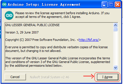
Double click Arduino-1.5.6 .exe. Click “I agree”;
Click “Next”;
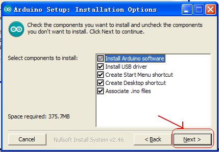
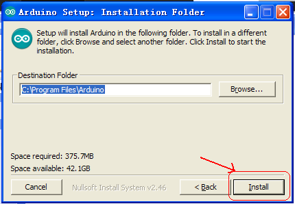
And then “Install”;
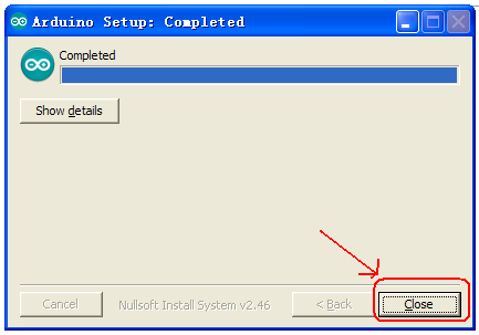
Wait for the installation to be completed, click close
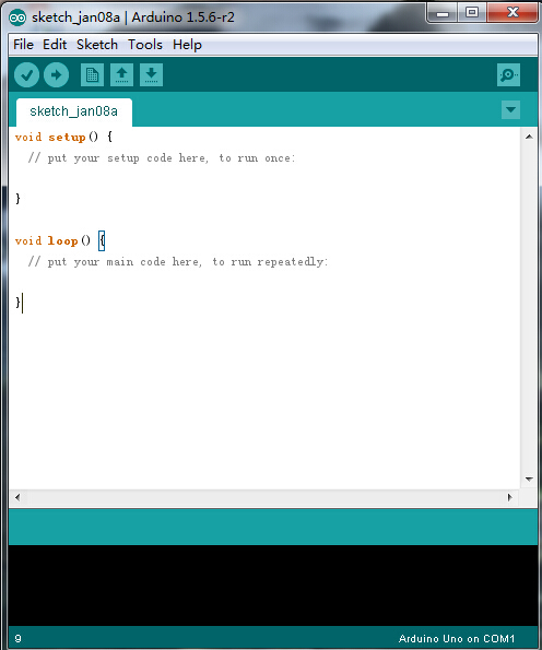
Below is how Arduino 1.5.6 looks like.
Next, let’s install Arduino driver.
For different operating system, there may be slight difference in installation method. Below is an example in WIN 7.
When you connect Arduino Uno to your computer the first time, right click “Computer” —> “Properties”—> “Device manager”, you can see “Unknown devices”.
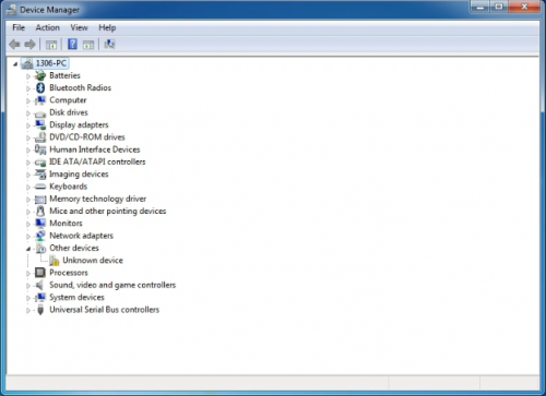
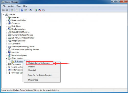
Click “Unknown devices”, select “Update Driver software”.
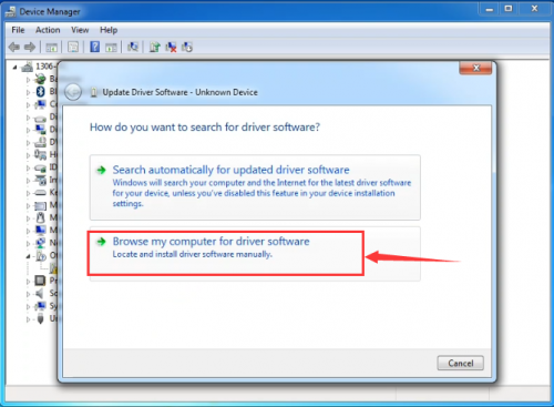
In this page, click “Browse my computer for driver software”.
Find the “drivers” file.
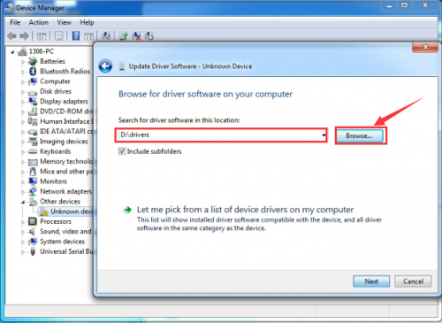
Click “Next”; select “Install this driver software anyway” to begin the installation.
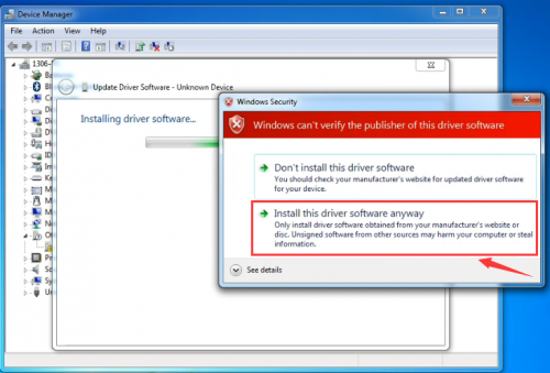
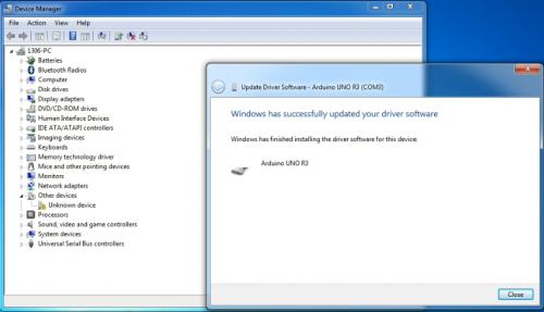
Installation completed; click “Close”.
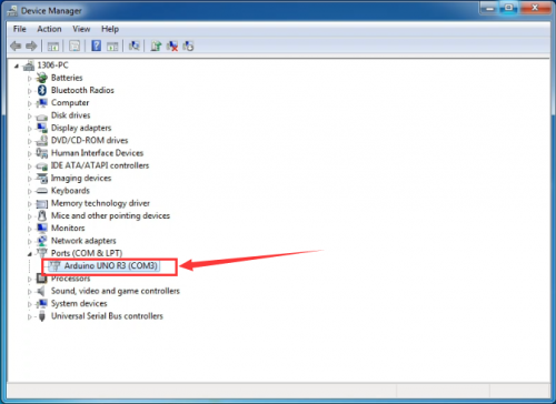
After driver is installed, go to “Device manager” again. Right click “Computer” —> “Properties”—> “Device manager”, you can see UNO device as below figure shows, also the Com port info.
Following is a sketch uploading example called “Hello World!”.
First, open Arduino IDE. In this example sketch, we program Arduino to display “Hello World!” in serial monitor when it receives a specific character string “R”; also the on-board D13 LED will blink once each time it receives “R”.
First, set up board; In “Tools”, select “Arduino Uno”.
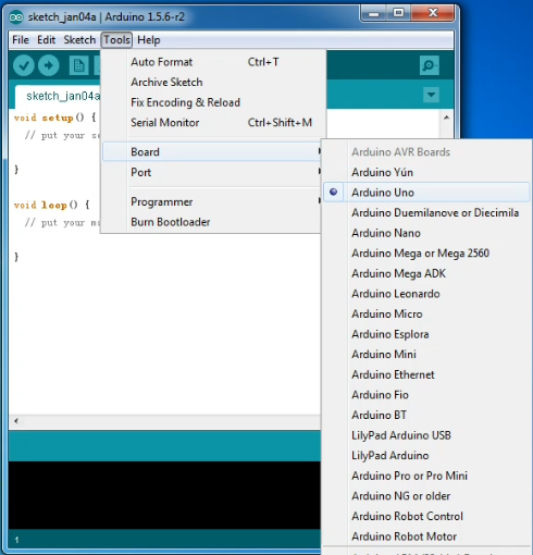
Next, set up COM port; In “Tools”, select “COM3”.
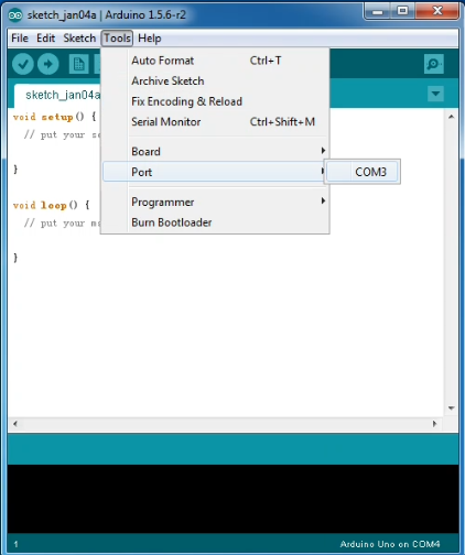
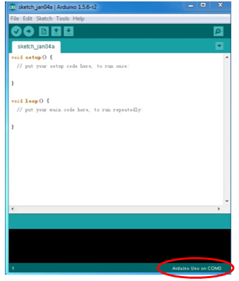
After selection, you can see indicated area is the same with settings in “Device manager”.
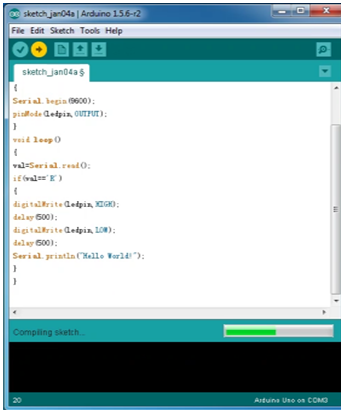
Copy the example sketch and paste it to the IDE; click “Verify ” to check compiling mistakes; click “Upload ” to upload the program to the board.
After uploading is done, open “serial monitor ”; enter “R”; click “Send”, the serial monitor will display “Hello World!” and the D13 LED will blink once.
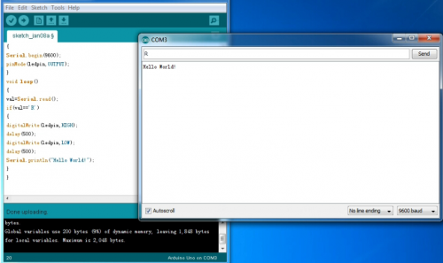
Congratulations! Your first sketch uploading is a success!
5. Project Details
Project 1: Obstacle-avoidance Tank
Introduction
This project is a simple obstacle avoidance tank robot system based on Arduino, including the software and hardware design. The controller part is a UNO board. Ultrasonic sensor and servo motors are used to detect whether there are obstacles ahead, and feedback the signal to UNO. UNO will analyze the signal to determine and control the motors movement to adjust Tank moving direction. Therefore the tank robot can automatically avoid obstacles.
Working principle
1. Ultrasonic ranging: the controller sends out a a high level signal of more than 10μs, when the output pin receives the high level signal, the timer will be on; when the signal changes to low level, we can read the time period of the timer, which is the time used for this ultrasonic wave transceiving. Together with its transmission speed, we can calculate the distance.
2. After we use the ultrasonic sensor to detect the distance from an obstacle, we can control the movement of the Tank according to the data.
3. If the distance from the obstacle is < 10cm, the Tank moves backward; if the distance is >=25cm, the Tank moves forward; if the distance is <25cm, we control the movement of the servo motors to measure the distance of the left and right. If both the distance are <10cm, the Tank moves backward; if the distance are both >= 10cm, and distance on the left is more than the distance on the right, the Tank moves to the left; if distance on the left is <= the distance on the right, the Tank moves to the right.
Performance parameter
1. Working voltage: DC5V
2. Static Current: <2mA
3. Level output: high 5V
4. Level output: low 0V
5. Induction angle: <15°
6. Detecting range : 2cm-450cm
7. Detecting accuracy: 0.3cm
Detecting principle
(1) use IO port to trigger the ranging, with at least 10μs high level signal;
(2) the module automatically sends 8 40khz square waves and automatically detect whether there is returned waves;
(3) if there is signal returned, the IO port will output a low level signal. The lasting time of the high level signal is the time between the launching and receiving of the ultrasonic signal. The detecting range= (high level lasting time*speed of sound(340M/S))/2 。
Usage
1. The sensor has 4 pins, Vcc, Trig, Echo, and Gnd. Vcc and Gnd is for power supply, Trig as signal transmitting end (connect to D5), Echo as signal receiving end (connect to D4).
2. Open serial monitor; set baud rate to 9600; we can see the distance value from the obstacle in cm.
Module test program
int inputPin = 4;    // set Echo pin to D4
  int outputPin =5;    // set Trig pin to D4
  void setup()
 {
  Serial.begin(9600);
  pinMode(inputPin, INPUT);    // define sensor pin as input
  pinMode(outputPin, OUTPUT);  // define sensor pin as output
 }
 void loop()
 {
  digitalWrite(outputPin, LOW);   // ultrasonic sensor transmit low level signal 2μs
  delayMicroseconds(2);
  digitalWrite(outputPin, HIGH);  // ultrasonic sensor transmit high level signal 10μs, at least 10μs
  delayMicroseconds(10);
  digitalWrite(outputPin, LOW);    // keep transmitting low level signal
  float Fdistance = pulseIn(inputPin, HIGH);  // read the time in between
  Fdistance= Fdistance/5.8/10;       // convert the time into distance (unit: cm)
  Serial.println(Fdistance);
  }
Schematic and connection diagram
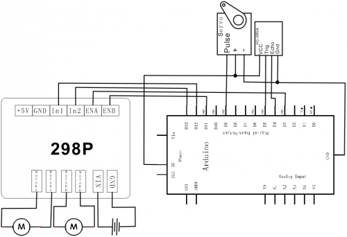
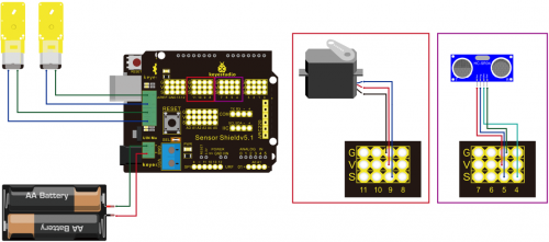
Obstacle avoidance Tank Robot program
/*
    L = Left
    R = Right
    F = forward
    B = backward
*/
#include <Servo.h>
int pinLB = 12;     // define pin 12
int pinLF = 3;     // define pin 3
int pinRB = 13;    // define pin 13
int pinRF = 11;    // define pin 11
////////////////////////////////
int inputPin = 4;    // define pin for sensor echo
int outputPin =5;    // define pin for sensor trig

int Fspeedd = 0;      // forward speed
int Rspeedd = 0;      // right speed
int Lspeedd = 0;      // left speed
int directionn = 0;   // forward=8 backward=2 left=4 right=6
Servo myservo;        // set myservo
int delay_time = 250; // settling time after steering servo motor moving B

int Fgo = 8;         // Move F
int Rgo = 6;         // move to the R
int Lgo = 4;         // move to the L
int Bgo = 2;         // move B

void setup()
 {
  Serial.begin(9600);     // Define motor output pin
  pinMode(pinLB,OUTPUT); // pin 12
  pinMode(pinLF,OUTPUT); // pin 3 (PWM)
  pinMode(pinRB,OUTPUT); // pin 13
  pinMode(pinRF,OUTPUT); // pin 11 (PWM)
  pinMode(inputPin, INPUT);    // define input pin for sensor
  pinMode(outputPin, OUTPUT);  // define output pin for sensor
  myservo.attach(9);    // Define servo motor output pin to D9 (PWM)
 }
void advance()     // move forward
    {
    digitalWrite(pinLB,LOW);    // right wheel moves forward
digitalWrite(pinRB, LOW);  // left wheel moves forward
    analogWrite(pinLF,255);
    analogWrite(pinRF,255);
    }
void stopp()         // stop
    {
     digitalWrite(pinLB,HIGH);
     digitalWrite(pinRB,HIGH);
     analogWrite(pinLF,0);
     analogWrite(pinRF,0);
    }
void right()        // turn right (single wheel)
    {

   digitalWrite(pinLB,HIGH);  // wheel on the left moves forward
   digitalWrite(pinRB,LOW); // wheel on the right moves backward
   analogWrite(pinLF, 255);
   analogWrite(pinRF,255);
    }
void left()         // turn left (single wheel)
    {
   digitalWrite(pinLB,LOW);  // wheel on the left moves backward
   digitalWrite(pinRB,HIGH); // wheel on the right moves forward
   analogWrite(pinLF, 255);
   analogWrite(pinRF,255);
    }

void back()          // move backward
    {
     digitalWrite(pinLB,HIGH);  // motor moves to left rear
     digitalWrite(pinRB,HIGH);  // motor moves to right rear
     analogWrite(pinLF,255);
     analogWrite(pinRF,255);
    }
void detection()        // measure 3 angles (0.90.179)
    {
      int delay_time = 250;   // stabilizing time for servo motor after moving backward
      ask_pin_F();            // read the distance ahead
     if(Fspeedd < 10)         // if distance ahead is <10cm
      {
      stopp();               // clear data
      delay(100);
      back();                // move backward for 0.2S
      delay(200);
      }
      if(Fspeedd < 25)         // if distance ahead is <25cm
      {
        stopp();
        delay(100);             // clear data
        ask_pin_L();            // read distance on the left
        delay(delay_time);      // stabilizing time for servo motor
        ask_pin_R();            // read distance on the right
        delay(delay_time);      // stabilizing time for servo motor

        if(Lspeedd > Rspeedd)   // if distance on the left is >distance on the right
        {
          directionn = Lgo;      // move to the L
        }

        if(Lspeedd <= Rspeedd)   // if distance on the left is <= distance on the right
        {
         directionn = Rgo;      // move to the right
        }

        if (Lspeedd < 10 && Rspeedd < 10)   // if distance on left and right are both <10cm
        {
         directionn = Bgo;      // move backward
        }
      }
      else                      // if distance ahead is >25cm
      {
        directionn = Fgo;        // move forward
      }

    }
void ask_pin_F()   // measure the distance ahead
    {
      myservo.write(90);
      digitalWrite(outputPin, LOW);   // ultrasonic sensor transmit low level signal 2μs
      delayMicroseconds(2);
      digitalWrite(outputPin, HIGH);  // ultrasonic sensor transmit high level signal10μs, at least 10μs
      delayMicroseconds(10);
      digitalWrite(outputPin, LOW);    // keep transmitting low level signal
      float Fdistance = pulseIn(inputPin, HIGH);  // read the time in between
      Fdistance= Fdistance/5.8/10;       // convert time into distance (unit: cm)
      Fspeedd = Fdistance;              // read the distance into Fspeedd
    }
 void ask_pin_L()   // measure distance on the left
    {
      myservo.write(5);
      delay(delay_time);
      digitalWrite(outputPin, LOW);   // ultrasonic sensor transmit low level signal 2μs
      delayMicroseconds(2);
      digitalWrite(outputPin, HIGH);  // ultrasonic sensor transmit high level signal10μs, at least 10μs
      delayMicroseconds(10);
      digitalWrite(outputPin, LOW);    // keep transmitting low level signal
      float Ldistance = pulseIn(inputPin, HIGH);  // read the time in between
      Ldistance= Ldistance/5.8/10;       // convert time into distance (unit: cm)
      Lspeedd = Ldistance;              // read the distance into Lspeedd
    }
void ask_pin_R()   //  measure distance on the right
    {
      myservo.write(177);
      delay(delay_time);
      digitalWrite(outputPin, LOW);   // ultrasonic sensor transmit low level signal 2μs
      delayMicroseconds(2);
      digitalWrite(outputPin, HIGH);  // ultrasonic sensor transmit high level signal10μs, at least 10μs
      delayMicroseconds(10);
      digitalWrite(outputPin, LOW);    // keep transmitting low level signal
      float Rdistance = pulseIn(inputPin, HIGH);  // read the time in between
      Rdistance= Rdistance/5.8/10;       // convert time into distance (unit: cm)
      Rspeedd = Rdistance;              // read the distance into Rspeedd
    }

void loop()
  {
    myservo.write(90);  // home set the servo motor, ready for next measurement
    detection();        // measure the angle and determine which direction to move
   if(directionn == 2)  // if directionn= 2
   {
     back();
     delay(800);                    //  go backward
     left() ;
     delay(200);              // Move slightly to the left (to prevent stuck in dead end)
   }
   if(directionn == 6)           // if directionn = 6
   {
     back();
     delay(100);
     right();
     delay(600);                 // turn right
   }
   if(directionn == 4)          // if directionn = 4
   {
     back();
     delay(600);
     left();
     delay(600);                  // turn left
   }
   if(directionn == 8)          // if directionn = 8
   {
    advance();                 // move forward
    delay(100);
   }
   }
