KS0080(81,82)Maker Learning Kit for Arduino
Introduction
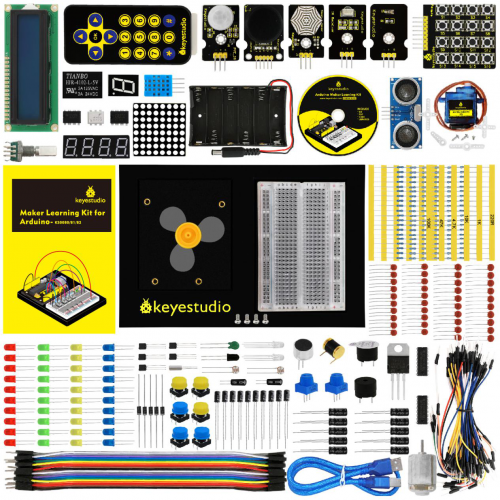
Want to have enormous fun? Want to DIY some projects? Want to be more creative and more imaginative? Want your child to learn science while having fun? As long as you are willing to create, dare to experience new things, have a passion for scientific experiments, this maker kit is your best customized choice! Maker learning kit is a DIY kit for scientific experiments based on ARDUINO. Together with controller, sensors, electronic components, you can build different DIY projects. It can not only enhance operational ability of teenagers, but also develop their imagination and creativity. Children who are into DIY can learn electronics, physics, science knowledge and software programming while playing; teachers can use it to achieve innovative teaching; makers can use it for design verification of product prototype.
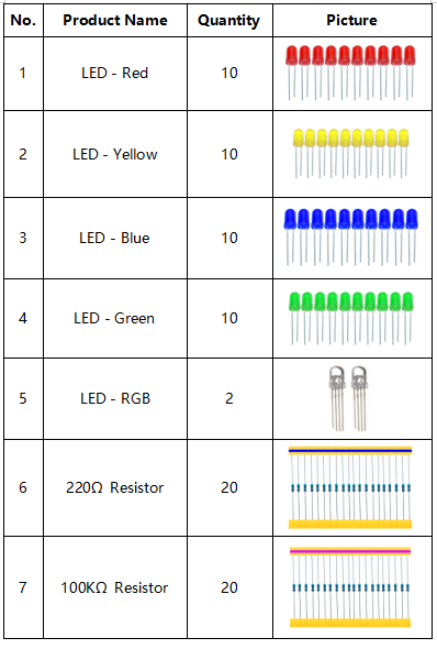
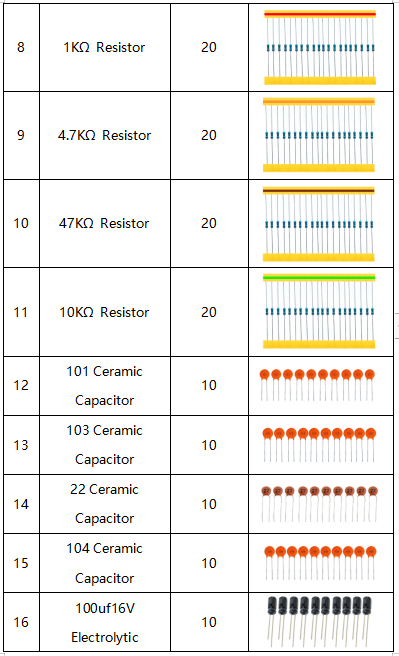
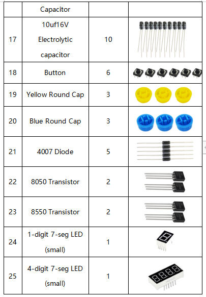
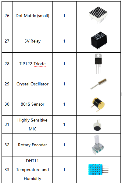
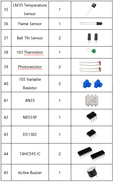
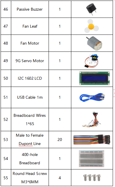
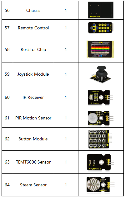
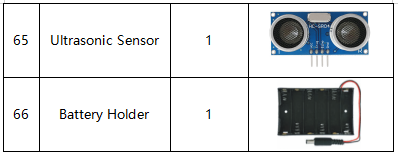
Component List
NOTE: KS0080 Kit doesn’t include main board; KS0081 Kit Includes V4.0 board; KS0082 KIT Includes MEGA 2560.
Install Arduino IDE and Driver
Download software
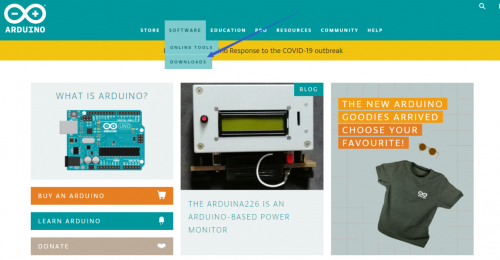
When we get control board, we need to download Arduino IDE and driver firstly. You could download Arduino IDE from the official website: https://www.arduino.cc/, click the SOFTWARE on the browse bar, click “DOWNLOADS” to enter download page, as shown below:
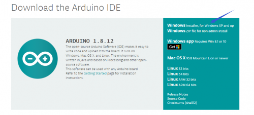
There are various versions for Arduino, just download a suitable version for your system, we will take WINDOWS system as an example to show you how to download and install.
There are two versions for WINDOWS system, one is installed version, another one is download version, you just need to download file to computer directly and unzip it. These two versions can be used normally. Choose one and download on your computer.
You just need to click JUST DOWNLOAD, then click the downloaded file to install it. And when the ZIP file is downloaded, you can directly unzip and start it.
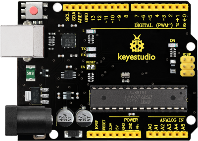
Keyestudio V4.0 Development Board
We need to know keyestudio V4.0 development board, as a core of this smart car.
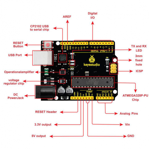
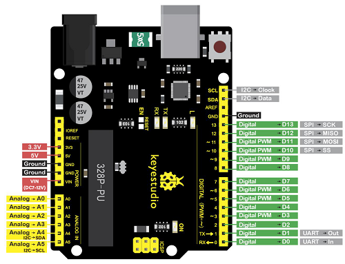
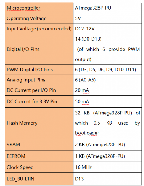
keyestudio V4.0 development board is an Arduino uno-compatible board, which is based on ATmega328P MCU, and with a cp2102 Chip as a UART-to-USB converter.
It has 14 digital input/output pins (of which 6 can be used as PWM outputs), 6 analog inputs, a 16 MHz quartz crystal, a USB connection, a power jack, 2 ICSP headers and a reset button.
It contains everything needed to support the microcontroller; simply connect it to a computer with a USB cable or power it via an external DC power jack (DC 7-12V) or via female headers Vin/ GND(DC 7-12V) to get started.
Keyestudio MEGA 2560 Board
Keyestudio Mega 2560 R3 is a microcontroller board based on the ATMEGA2560-16AU , fully compatible with ARDUINO MEGA 2560 R3. 图
It has 54 digital input/output pins (of which 15 can be used as PWM outputs), 16 analog inputs, 4 UARTs (hardware serial ports), a 16 MHz crystal oscillator, a USB connection, a power jack, 1 ICSP header, and a reset button. The built-in ICSP port can burn the firmware for ATMEGA2560-16AU directly. This chip is burnt the firmware well before leaving the factory, therefore, we hardly use it. We can power on by USB wire, DC head and Vin GND pins. To facilitate wiring, a 0.5 m USB wire is provided for you.
图
Specialized Functions of Some Pins: 1. Serial Communication: D0 (RX0) and D1 (TX1); Serial 1: D19 (RX1) and D18 (TX1); Serial 2: D17 (RX2) and D16 (TX2); Serial 3: D15 (RX3) and D14 (TX3). Used to receive (RX) and transmit (TX) TTL serial data. Pins 0 and 1 are also connected to the corresponding pins of the CP2102 USB-to-TTL Serial chip. 2. PWM Pins (Pulse-Width Modulation): D2 to D13, and D44 to D46. Provide 8-bit PWM output with the analogWrite() function. 3. External Interrupts: D2 (interrupt 0), D3 (interrupt 1), D18 (interrupt 5), D19 (interrupt 4), D20 (interrupt 3), and D21 (interrupt 2). These pins can be configured to trigger an interrupt on a low level, a rising or falling edge, or a change in level. See the attachInterrupt() function for details. 4. SPI communication: D53 (SS), D52 (SCK), D51 (MOSI), D50 (MISO). These pins support SPI communication using theSPI library. The SPI pins are also broken out on the ICSP header, which is physically compatible with the Arduino Uno. 5. IIC communication: D20 (SDA); D21 (SCL). Support TWI communication using the Wire library.
Installing driver
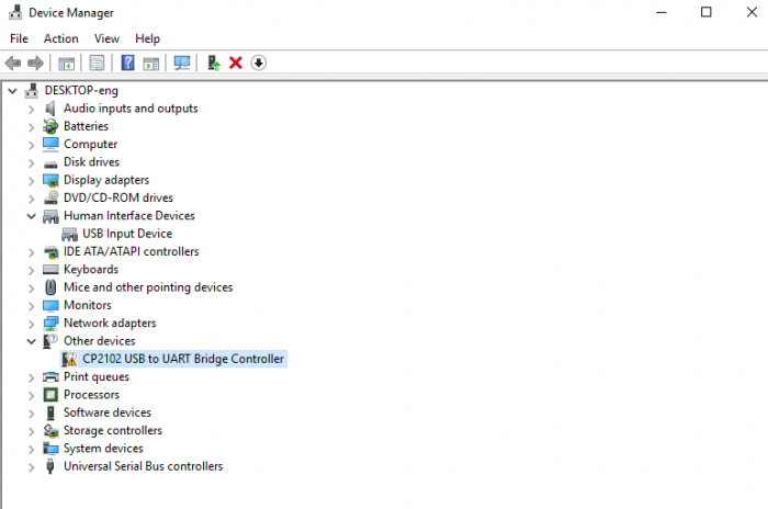
Let’s install the driver of keyestudio PLUS control board. The USB-TTL chip on PLUS board adopts CP2102 serial chip. The driver program of this chip is included in Arduino 1.8 version and above, which is convenient. Plug on USB port of board, the computer can recognize the hardware and automatically install the driver of CP2102.
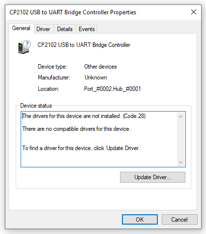
If install unsuccessfully, or you intend to install manually, open the device manager of computer. Right click Computer----- Properties----- Device Manager.
There is a yellow exclamation mark on the page, which implies installing the driver of CP2102 unsuccessfully. Then we double click the hardware and update the driver.
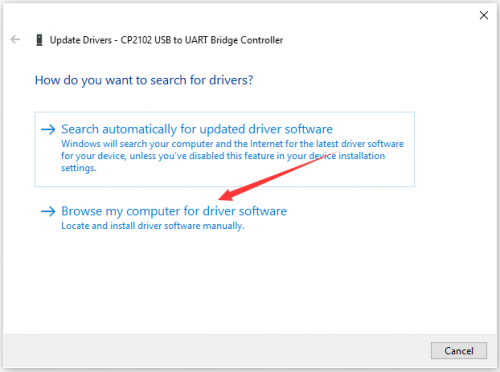
Click “OK” to enter the following page, click “browse my computer for updated driver software”, find out the installed or downloaded ARDUINO software. As shown below:
There is a DRIVERS folder in Arduino software installed package(![]() ), open driver folder and you can see the driver of CP210X series chips.
), open driver folder and you can see the driver of CP210X series chips.
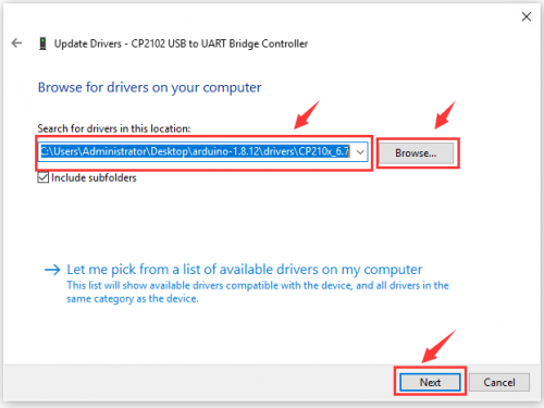
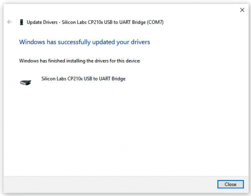
We click “Browse”, then find out the driver folder, or you could enter “driver” to search in rectangular box, then click “next”, the driver will be installed successfully. (I place Arduino software folder on the desktop, you could follow my way)
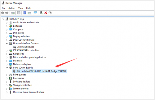
Open device manager, we will find the yellow exclamation mark disappear. The driver of CP2102 is installed successfully.
Arduino IDE Setting
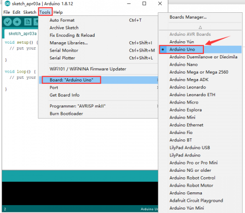
To avoid the errors when uploading the program to the board, you need to select the correct Arduino board that matches the board connected to your computer.
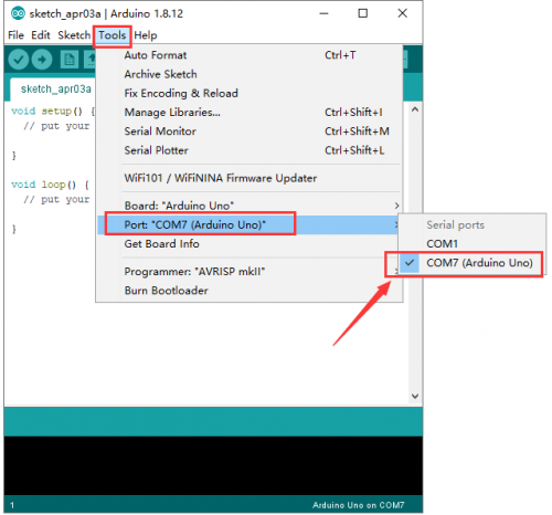
Then come back to the Arduino software, you should click Tools→Board, select the board. (as shown below)
Then select the correct COM port (you can see the corresponding COM port after the driver is successfully installed)
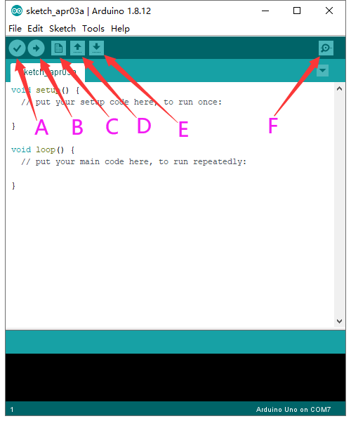
Before uploading the program to the board, let’s demonstrate the function of each symbol in the Arduino IDE toolbar.
A- Used to verify whether there is any compiling mistakes or not.
B- Used to upload the sketch to your Arduino board.
C- Used to create shortcut window of a new sketch.
D- Used to directly open an example sketch.
E- Used to save the sketch.
F- Used to send the serial data received from board to the serial monitor.
Start your first program
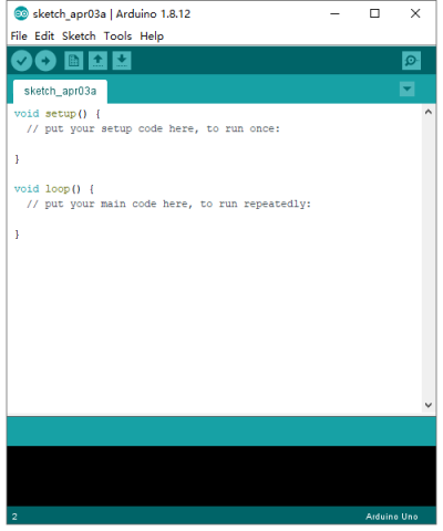
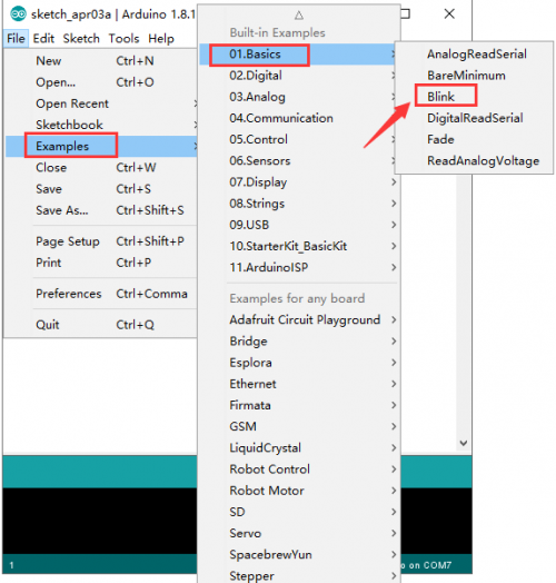
Open the file to select Example, choose BLINK from BASIC, as shown below:
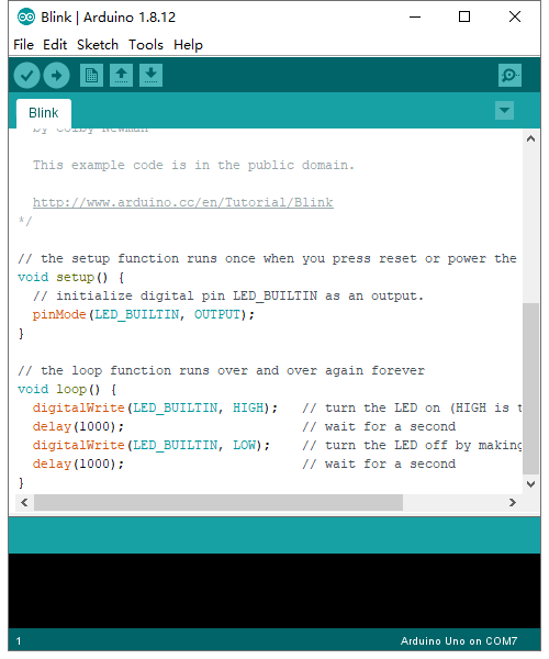
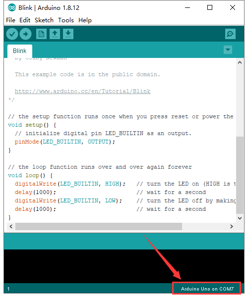
Set board and COM port, the corresponding board and COM port are shown on the lower right of IDE.
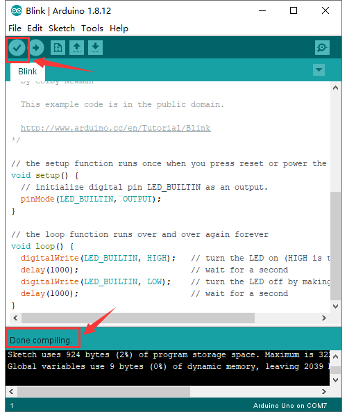
Click ![]() to start compiling the program, check errors.
to start compiling the program, check errors.
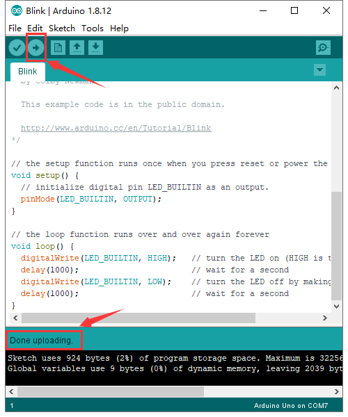
Click ![]() to upload the program, upload successfully.
to upload the program, upload successfully.
Upload the program successfully, the onboard LED lights on for 1s, lights off for 1s. Congratulation, you finish the first program.
Add Project Libraries
What are Libraries ?
Libraries are a collection of code that makes it easy for you to connect to a sensor,display, module, etc.
For example, the built-in LiquidCrystal library helps talk to LCD displays. There are hundreds of additional libraries available on the Internet for download.
The built-in libraries and some of these additional libraries are listed in the reference.
How to Install a Library ?
Here we will introduce the most simple way for you to add libraries.
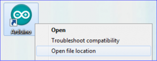
Step 1:After downloading well the Arduino IDE, you can right-click the icon of Arduino IDE.
Find the option "Open file location" shown as below:
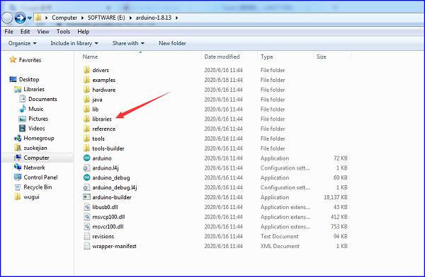
Step 2: Enter it to find out libraries folder which is the library file of Arduino.
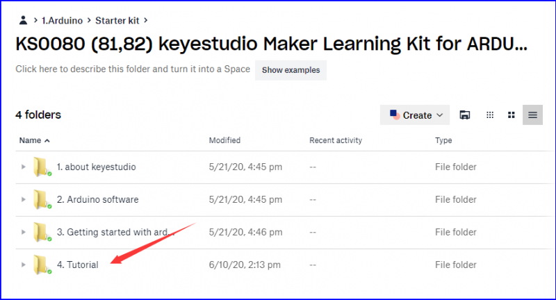
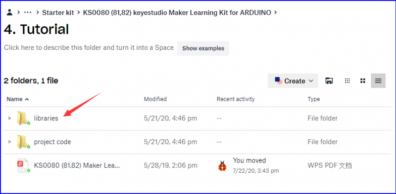
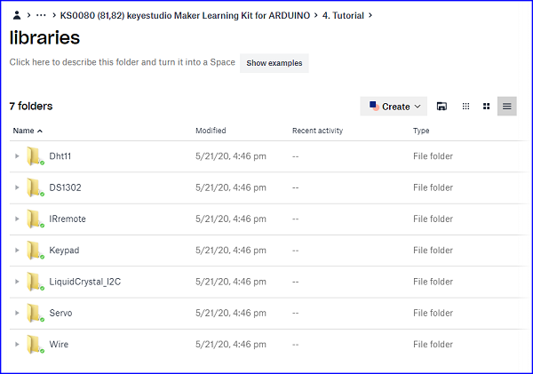
Step 3 Next to find out the“libraries”folder of this kit(seen in the link https//fs.keyestudio.com/KS0080-81-82).
You just need to replicate and paste above libraries into the libraries folder of Arduino IDE.
Then the libraries of this kit are installed successfully, as shown below

Note the Arduino software download and the driver installation of keyetudio Mega 2560 R3 board is similar to arduino V4.0 board.
Project
Project 1: Hello World
(1)Introduction
As for starters, we will begin with something simple. In this project, you only need an Arduino and a USB Cable to start the "Hello World!" experiment. This is not only a communication test of your Arduino and PC, but also a primer project for you to have your first try in the Arduino world!
(2) Hardware Required
- V4.0 Board or MEGA 2650 Board *1
- USB Cable *1
(3) Sample Code After installing driver for Arduino, open Arduino software and compile code that enables Arduino to print "Hello World!" under your instruction. Of course, you can compile code for Arduino to continuously echo "Hello World!" without instruction. A simple If () statement will do the instruction trick. With the onboard LED connected to pin 13, you can instruct the LED to blink first when Arduino gets an instruction and then print "Hello World!”.
/*
keyestudio Maker learning kit
Project 1
Hello World
http//www.keyestudio.com
*/
int val;//define variable val
int ledpin=13;// define digital interface 13
void setup()
{
  Serial.begin(9600);// set the baud rate at 9600 to match the software set up. When connected to a specific device, (e.g. bluetooth), the baud rate needs to be the same with it.
  pinMode(ledpin,OUTPUT);// initialize digital pin 13 as output. When using I/O ports on an Arduino, this kind of set up is always needed.
}
void loop()
{
  val=Serial.read();// read the instruction or character from PC to Arduino, and assign them to Val.
  if(val=='R')// determine if the instruction or character received is “R”.
  {  // if it’s “R”,
    digitalWrite(ledpin,HIGH);// set the LED on digital pin 13 on.
    delay(500);
    digitalWrite(ledpin,LOW);// set the LED on digital pin 13 off.    delay(500);
    Serial.println("Hello World!");// display“Hello World!”string.
  }
}
////////////////////////////////////////////////////////////////
(4) Test Result
Click serial monitor,Input R,LED 13 will blink once,PC will receive information from Arduino: Hello World
After you choosing the right port,the experiment is very easy for you!
Project 2: LED Blinking
(1) Introduction
Blinking LED experiment is quite simple. In the "Hello World!" program, we have used LED. This time, we are going to connect an LED to one of the digital pins rather than using LED13 which is soldered to the board. Apart from an Arduino and a USB cable, it will need extra parts as below:
(2) Hardware Required
- V4.0 Board or MEGA 2650 Board *1
- USB Cable *1
- Red M5 LED*1
- 220Ω Resistor*1
- Breadboard*1
- Breadboard Jumper Wire *2
(3) Little Knowledge
LED is a type of semiconductor called "Light Emitting Diode "which is an electronic device made of semiconductor materials (silicon, selenium, germanium, etc.). It is dubbed indicator, digital and word display in circuit and device. It has positive and negative poles. The short leg is negative pole, the long one is positive pole.
Resistor:Resistor is the electronic component in the circuit, which limits and regulates current flow. Its unit is (Ω). The units larger than ohms are kiloohms (KΩ) and megaohms (MΩ). When in use, in addition to the size of the resistance, you must also pay attention to its power. In the project, the leads at both ends of the resistor should be bent at a 90° angle to fit the breadboard properly. If the lead is too long, it can be cut to an appropriate length.
A breadboard is used to build and test circuits quickly before finalizing any circuit design. The breadboard has many holes into which circuit components like ICs and resistors can be inserted. A typical breadboard is shown below:
The bread board has strips of metal which run underneath the board and connect the holes on the top of the board. The metal strips are laid out as shown below. Note that the top and bottom rows of holes are connected horizontally while the remaining holes are connected vertically.
To use the bread board, the legs of components are placed in the holes. Each set of holes connected by a metal a strip underneath forms anode
(4)Circuit Connection
We follow below diagram from the experimental schematic link. Here we use digital pin 10. We connect LED to a 220 ohm resistor to avoid high current damaging the LED.
Connection for V4.0:
Connection for 2560 R3:
(5)Sample Code
/*
keyestudio Maker learning kit
Project 2
LED Blinking
http//www.keyestudio.com
*/

int ledPin = 10; // define digital pin 10.
void setup()
{
pinMode(ledPin, OUTPUT);// define pin with LED connected as output.
}
void loop()
{
digitalWrite(ledPin, HIGH); // set the LED on.
delay(1000); // wait for a second.
digitalWrite(ledPin, LOW); // set the LED off.
delay(1000); // wait for a second
}
//////////////////////////////////////////////////////////
(6)Test Result
After downloading this program, in the experiment, you will see the LED connected to pin 10 turning on and off, with approximate interval of one second. The blinking LED experiment is now completed. Thank you!
Project 3: Breathing LED
(1)Introduction After the first two projects, I believe you’ve grown familiar with Arduino. In this project, we will use LED to do something else, simulating breath. Sounds cool? Well, let’s get on with it. We will still be using the same hardware from project 2.
(2) Hardware Required
- V4.0 Board or MEGA 2650 Board *1
- USB Cable *1
- Red M5 LED*1
- 220Ω Resistor*1
- Breadboard*1
- Breadboard Jumper Wire*2
(3)Connection Diagram
Connection for V4.0:
Connection for MEGA 2560:
(4)Sample Code
/*
keyestudio Maker learning kit
Project 3
Breathing LED
http//www.keyestudio.com
*/
int ledPin = 11; // define digital pin 11
void setup()
{
pinMode(ledPin, OUTPUT);// define LED pin as output
}
void loop()
{
for (int a=0; a<=255;a++)// set the LED to be brighter gradually
{
analogWrite(ledPin,a); // turn on LED, regulate light brightness, ranging from 0-255, 255 is the brightest
delay(10); // wait for 0.01S
}
for (int a=255; a>=0;a--) // set LED to be dimming gradually
{
analogWrite(ledPin,a); // turn on LED, regulate light brightness, ranging from 0-255, 255 is the brightest
delay(10); // wait for 0.01S
}
delay(1000);// wait for 1S
}
//////////////////////////////////////////////////////////
(5)Test Result
LED becomes brighter gradually, wait for 0.01S, then dimming gradually, wait for 1S, and then cycles on, just like the LED is breathing.
Project 4: PWM Light Control
(1) Introduction
PWM, short for Pulse Width Modulation, is a technique used to encode analog signal level into digital ones.
A computer cannot output analog voltage but only digital voltage values such as 0V or 5V. So we use a high resolution counter to encode a specific analog signal level by modulating the duty cycle of PMW.
The PWM signal is also digitalized because in any given moment, fully on DC power supply is either 5V (ON), or 0V (OFF). The voltage or current is fed to the analog load (the device that uses the power) by repeated pulse sequence being ON or OFF. Being on, the current is fed to the load; being off, it's not. With adequate bandwidth, any analog value can be encoded using PWM. The output voltage value is calculated via the on and off time.
Output voltage = (turn on time/pulse time) * maximum voltage value
PWM has many applications: lamp brightness regulating, motor speed regulating, sound making, etc. The following are the three basic parameters of PMW:
1. The amplitude of pulse width (minimum / maximum) 2. The pulse period (The reciprocal of pulse frequency in 1 second) 3. The voltage level(such as:0V-5V) There are 6 PMW interfaces on Arduino, namely digital pin 3, 5, 6, 9, 10, and 11. In previous experiments, we have done "button-controlled LED", using digital signal to control digital pin, also one about potentiometer. This time, we will use a potentiometer to control the brightness of the LED.
(2) Hardware Required
- V4.0 Board or MEGA 2650 Board *1
- USB Cable *1
- Potentiometer*1
- Red M5 LED*1
- 220Ω Resistor*1
- Breadboard*1
- Breadboard Jumper Wire*6
(3) Connection Diagram
The input of potentiometer is analog, so we connect it to analog port, and LED to PWM port. Different PWM signal can regulate the brightness of the LED.
Connection for V4.0:
Connection for 2560 R3:
(4) Sample Code
In the program compiling process, we will use the analogWrite (PWM interface, analog value) function. In this experiment, we will read the analog value of the potentiometer and assign the value to PWM port, so there will be corresponding change to the brightness of the LED. One final part will be displaying the analog value on the screen. You can consider this as the "analog value reading" project adding the PWM analog value assigning part. Below is a (5)Sample Code for your reference.
/*
keyestudio Maker learning kit
Project 4
PWM Light Control
http//www.keyestudio.com
*/
int potpin=0;// initialize analog pin 0
int ledpin=11;//initialize digital pin 11(PWM output)
int val=0;// Temporarily store variables' value from the sensor
void setup()
{
pinMode(ledpin,OUTPUT);// define digital pin 11 as “output”
Serial.begin(9600);// set baud rate at 9600
// attention: for analog ports, they are automatically set up as “input”
}
void loop()
{
val=analogRead(potpin);// read the analog value from the sensor and assign it to val
Serial.println(val);// display value of val
analogWrite(ledpin,val/4);// turn on LED and set up brightness(maximum output of PWM is 255)
delay(10);// wait for 0.01 second
}
//////////////////////////////////////////////////////////
(5) Test Result
After downloading the program, when we rotate the potentiometer knob, we can see changes of the displaying value, also obvious change of the LED brightness on the breadboard.
Project 5: Traffic Light
For more details, please navigate the link:
